

FprEN IEC 60974-1:2026
(Main)Arc welding equipment - Part 1: Welding power sources
- Status
- Not Published
- Publication Date
- 14-Feb-2027
- Technical Committee
- CLC/TC 26 - Electric welding
- Current Stage
- 5020 - Vote circulated - Formal Approval
- Start Date
- 02-Oct-2026
- Due Date
- 07-May-2026
- Completion Date
- 02-Oct-2026

FprEN IEC 60974-1:2026 is the CLC draft of IEC 60974-1, Arc welding equipment - Part 1: Welding power sources. It specifies safety and performance requirements for welding power sources and plasma cutting systems used for industrial and professional use, including battery-powered and mechanically driven units. It is the reference for manufacturers, test laboratories, and quality or purchasing teams that need a common basis for checking arc welding power sources.
What does FprEN IEC 60974-1:2026 specify?
FprEN IEC 60974-1:2026 covers welding power sources for arc welding and allied processes, with typical allied processes noted as electric arc cutting and arc spraying. It applies to equipment supplied by a voltage not exceeding 1 000 V, battery supplied, or driven by mechanical means, and it includes battery-powered WELDING POWER SOURCES in Annex O.
The document excludes limited duty arc welding and cutting power sources designed mainly for laypersons and built to IEC 60974-6. It also states that it is not for testing during periodic maintenance or after repair, and its scope note says it does not include electromagnetic compatibility (EMC) requirements.
The document is organized into 17 clauses and annexes A to P. The main clauses cover scope, normative references, terms and definitions, environmental conditions, tests, electric shock protection, thermal requirements, thermal protection, abnormal operation, supply connection, output, control circuits, hazard reducing devices, mechanical provisions, the rating plate, output adjustment, and instructions and markings.
| Annex | What it covers |
|---|---|
| Annex A | Nominal voltages of supply networks |
| Annex B | Example of a combined dielectric test |
| Annex C | Unbalanced load in AC tungsten-inert-gas WELDING POWER SOURCES |
| Annex D | Extrapolation of temperature to time of shutdown |
| Annex E | Construction of SUPPLY CIRCUIT terminals |
| Annex F | Cross-reference to non-SI units |
| Annex G | Suitability of the supply network for true RMS supply current measurement |
| Annex H | Plotting of STATIC CHARACTERISTICS |
| Annex I | Test methods for a 10 Nm impact |
| Annex J | Thickness of sheet metal for enclosures |
| Annex K | Examples of RATING PLATES |
| Annex L | Graphical symbols for arc welding equipment |
| Annex M | Efficiency and IDLE STATE power measurement |
| Annex N | TOUCH CURRENT measurement |
| Annex O | Battery-powered WELDING POWER SOURCES |
| Annex P | Isolation resistance measurements for BATTERY VOLTAGE CLASS B electric circuits |
What are the key requirements of FprEN IEC 60974-1:2026?
FprEN IEC 60974-1:2026 is mainly a safety standard. Its core requirements cover insulation, electric shock protection, thermal behaviour, fault handling, supply connection, output limits, mechanical strength, marking, and user information. In practice, it tells a manufacturer what to design, what to test, and what to put on the rating plate and in the instructions.
Electrical safety and insulation
- Clause 5.3 requires components and subassemblies that could create a hazard, such as power supplies and built-in information technology equipment, to be used within their rated limits and to meet applicable safety requirements. In practice, you cannot rely only on a component being "approved" if its use in the welding power source is more severe than the component standard covers.
- Clause 6.1 sets the insulation rules, including clearances, creepage distances, insulation resistance, dielectric strength, and the way insulation is chosen for different supply systems. The tables and figures in this clause matter because they define the physical distances and test voltages needed to keep live parts separated.
- Clause 6.2 requires enclosure protection for direct contact, with minimum IP21S for indoor use and IP23S for outdoor use, and IP2X for remote controls. For the reader, this means the enclosure and control hardware must match the intended environment, not just the electrical ratings.
- Clause 6.3 requires WELDING POWER SOURCES to be CLASS I or CLASS II EQUIPMENT, with the WELDING CIRCUIT treated separately, and it sets rules for the isolation between supply and welding windings. It also limits TOUCH CURRENT under fault conditions and gives the test configurations in Annex N. That matters because the protective earth path and leakage behaviour must stay safe even if one protective measure fails.
Thermal behaviour and fault conditions
- Clause 7 sets the heating test, temperature measurement methods, and limits for temperature rise. It also covers windings, commutators, slip-rings, and external surfaces. In practice, the equipment must survive the declared duty cycle without overheating parts that users touch or parts that can fail.
- Clause 8 requires THERMAL PROTECTION to prevent windings from exceeding the temperature limits and to stay inactive at rated maximum welding current and rated duty cycle. It also says the protection shall not reset until the temperature has fallen below the insulation class limit. This matters because thermal cut-out settings must be coordinated with the declared ratings on the machine.
- Clause 9 covers abnormal operation, including stalled fan, short circuit, overload, and capacitor short circuit tests. The intent is that a foreseeable fault should not create fire risk or hazardous breakdown. For a designer or tester, this means checking how the power source behaves when cooling, switching, or protection parts fail.
Supply connection, output, and control circuits
- Clause 10 governs the connection to the supply network, including supply voltage, multi-supply arrangements, terminal marking, protective circuit continuity, cable anchorage, inlet openings, on/off switching, supply cables, and attachment plugs. In practice, the mains side must be safe to install and robust under pull, strain, and repeated connection.
- Clause 11 sets output requirements, including RATED NO-LOAD VOLTAGE, TYPE TEST values of the CONVENTIONAL LOAD VOLTAGE, output switching devices, WELDING CIRCUIT connections, external device supply, auxiliary power supply, and welding cables. This clause is central for product selection because it defines the welding process, output character, and safety limits the user sees on the machine.
- Clause 12 requires CONTROL CIRCUITs to be tested at maximum load and to be insulated according to where they leave the enclosure and what other circuits they can touch. For remote controls, the working voltages must stay within the clause limits, which matters when a control pendant or external interface is added.
- Clause 13 defines HAZARD REDUCING DEVICEs and their requirements. These devices are used to reduce the shock risk caused by no-load voltage, so they are part of the safety concept for certain applications and environments.
Construction, marking, and instructions
- Clause 14 requires the equipment to be mechanically strong enough for normal service and to protect users from live and moving parts, while maintaining the required clearances. It includes enclosure requirements, handles, drop withstand, and tilting stability, so the product must stay safe after handling and transport.
- Clause 15 requires a clearly marked and durable RATING PLATE with the electrical and operational data needed for correct selection and use. The clause also gives tolerances for rated values, which matters when a buyer compares the machine data with the intended application.
- Clauses 16 and 17 cover output adjustment, markings, and instructions. These clauses matter because the user has to understand how to set the machine, identify controls and terminals, and use the equipment in the right operating conditions.
Battery-powered equipment
- Annex O applies the same style of safety requirements to BATTERY-powered WELDING POWER SOURCES and BATTERY packs. It covers environmental conditions, tests, protection against electric shock, thermal requirements, thermal protection, abnormal operation, connection to the supply network, mechanical provisions, the rating plate, and instructions and markings. For portable or hybrid equipment, Annex O is the part to read first.
What terms does FprEN IEC 60974-1:2026 define?
- WELDING POWER SOURCE - Equipment that supplies current and voltage with the characteristics needed for arc welding and allied processes, and it can also supply auxiliaries such as cooling liquid, consumable electrode, or shielding gas.
- CONVENTIONAL LOAD - A practically non-inductive constant resistive load with power factor not less than 0.99, used to give repeatable test conditions for output measurements.
- STATIC CHARACTERISTIC - The relationship between voltage and current at the output terminals when the WELDING POWER SOURCE is connected to a CONVENTIONAL LOAD.
- TYPE TEST - A test on one or more devices made to a given design to check whether that design meets the standard.
- ROUTINE TEST - A test on each individual device during or after manufacture to check whether it meets the standard or specified criteria.
- HAZARD REDUCING DEVICE - A device designed to reduce electric shock hazard that may originate from the NO-LOAD VOLTAGE.
- RATING PLATE - A permanently fixed plate that states the ratings and other required information of the equipment.
- REMOTE CONTROL - A device or circuit outside the equipment used for monitoring or operational control.
Who uses FprEN IEC 60974-1:2026?
FprEN IEC 60974-1:2026 is used by manufacturers of arc welding power sources, plasma cutting systems, and battery-powered welding equipment. It is also used by test laboratories, certification bodies, and compliance teams that verify electric shock protection, thermal behaviour, enclosure protection, and rating plate data.
Quality managers and buyers use it to check whether a machine meets the right safety basis for industrial and professional use. Design engineers use it when selecting insulation, protective circuits, output settings, controls, and markings. Operators and supervisors use the instructions and markings sections to understand how the machine should be set up and used.
What changed in FprEN IEC 60974-1:2026 from the previous edition?
FprEN IEC 60974-1:2026 is the seventh edition and it cancels and replaces the sixth edition published in 2021. The foreword lists these significant technical changes:
- new terms and definitions were added to Clause 3.1;
- verbal form changes from "may" to "can" from edition 6 were reviewed and corrected where needed;
- notes related to (EU) 2019/1784 were deleted in Clause 3.3.2, 15.3, 16.3.3, and M.1.1;
- Type Test requirements in Clause 5.4 were modified;
- a note was added to CLEARANCE verification with AC or DC voltage in Clause 6.1.2;
- Table 3 on minimum CREEPAGE DISTANCES was editorially adjusted to IEC 60664-1:2020/AMD1:2025;
- the capacitor short circuit test in Clause 9.5 was refined;
- the voltage reducing device test in Clause 13.2.1 was reworded for clarity;
- duty cycle requirements on the RATING PLATE in Clause 15.3 b) were reworded for clarity;
- abnormal operation test requirements in O.9.1 were aligned with Clause 9.1;
- Annex P was added.
Which standards are used with FprEN IEC 60974-1:2026?
| Standard | What it contributes |
|---|---|
| IEC 60245-6 | Rubber insulated cables for arc welding electrode cables |
| IEC 60445 | Identification of equipment terminals, conductor terminations, and conductors |
| IEC 60529 | IP Code for enclosure protection |
| IEC 60664-1:2020 and IEC 60664-1:2020/AMD1:2025 | Insulation coordination, clearances, creepage distances, and test principles |
| IEC 60664-3 | Use of coating, potting, or moulding for protection against pollution |
| IEC 60695-11-10 | Fire hazard test flame methods |
| IEC 60974-7 | Torches |
| IEC 60974-10 | Electromagnetic compatibility requirements |
| IEC 61140 | Common aspects of protection against electric shock |
| IEC 61558-2-4 and IEC 61558-2-6 | Transformers and power supply units used for isolation or safety isolation |
| IEC 62133-1:2017 and IEC 62133-2:2017/AMD1:2021 | Safety requirements for nickel and lithium batteries |
| IEC 62301:2011 | Standby power measurement |
| ISO 7010:2019 and its amendments | Registered safety signs used for markings and symbols |
The scope also points to IEC 60974-6 for limited duty arc welding and cutting power sources designed mainly for laypersons, and Clause 11.4.1 notes that devices complying with IEC 60974-12 meet one of the output-coupling protection requirements.
What does the FprEN IEC 60974-1:2026 document contain?
FprEN IEC 60974-1:2026 contains the test methods, limits, and worked examples that support the safety and performance requirements. It includes tables for clearances, creepage distances, insulation resistance, dielectric test voltages, temperature limits, protective circuits, supply network voltages, rating plate values, sheet-metal thickness, and battery-related marking.
It also includes procedures and figures for measuring touch current, no-load voltage, RMS and peak values, efficiency, idle state power, and isolation resistance. Annex H explains how to plot the STATIC CHARACTERISTIC, Annex M gives the measurement method and report template for efficiency and IDLE STATE power, and Annex N gives the measuring networks for TOUCH CURRENT.
Several annexes provide practical examples rather than requirements. Annex B gives a combined dielectric test example, Annex C shows how to simulate unbalanced load in AC tungsten-inert-gas welding, Annex D explains how to extrapolate temperature to shutdown time, Annex I gives 10 Nm impact test setups, Annex K shows example rating plates, and Annex L collects graphical symbols for controls, outputs, and warnings.
Relations
- Effective Date
- 29-Apr-2025
- Effective Date
- 22-Oct-2024
- Effective Date
- 22-Oct-2024
- Effective Date
- 31-Oct-2023
Get Certified
Connect with accredited certification bodies for this standard

DVS-ZERT GmbH
German welding certification society.
CARES (UK Certification Authority for Reinforcing Steels)
UK certification for reinforcing steels and construction.
EWF/IIW (European/International Welding Federation)
International welding personnel certification.
Sponsored listings
Frequently Asked Questions
FprEN IEC 60974-1:2026 is a draft published by CLC. Its full title is "Arc welding equipment - Part 1: Welding power sources". This standard covers: Arc welding equipment - Part 1: Welding power sources
Arc welding equipment - Part 1: Welding power sources
FprEN IEC 60974-1:2026 is classified under the following ICS (International Classification for Standards) categories: 25.160.30 - Welding equipment. The ICS classification helps identify the subject area and facilitates finding related standards.
FprEN IEC 60974-1:2026 has the following relationships with other standards: It is inter standard links to EN IEC 60974-1:2022/A13:2025, EN IEC 60974-1:2022/A11:2022, EN IEC 60974-1:2022/A12:2023, EN IEC 60974-1:2022. Understanding these relationships helps ensure you are using the most current and applicable version of the standard.
FprEN IEC 60974-1:2026 is associated with the following European legislation: EU Directives/Regulations: 2014/35/EU, 2019/1784; Standardization Mandates: M/511, M/559. When a standard is cited in the Official Journal of the European Union, products manufactured in conformity with it benefit from a presumption of conformity with the essential requirements of the corresponding EU directive or regulation.
FprEN IEC 60974-1:2026 is available in PDF format for immediate download after purchase. The document can be added to your cart and obtained through the secure checkout process. Digital delivery ensures instant access to the complete standard document.
Standards Content (Sample)
SLOVENSKI STANDARD
oSIST prEN IEC 60974-1:2025
01-september-2025
Oprema za obločno varjenje - 1. del: Viri varilnega toka
Arc welding equipment - Part 1: Welding power sources
Lichtbogenschweißeinrichtungen - Teil 1: Schweißstromquellen
Matériel de soudage à l'arc - Partie 1: Sources de courant de soudage
Ta slovenski standard je istoveten z: prEN IEC 60974-1:2025
ICS:
25.160.30 Varilna oprema Welding equipment
oSIST prEN IEC 60974-1:2025 en
2003-01.Slovenski inštitut za standardizacijo. Razmnoževanje celote ali delov tega standarda ni dovoljeno.
oSIST prEN IEC 60974-1:2025
oSIST prEN IEC 60974-1:2025
26/776/CDV
COMMITTEE DRAFT FOR VOTE (CDV)
PROJECT NUMBER:
IEC 60974-1 ED7
DATE OF CIRCULATION: CLOSING DATE FOR VOTING:
2025-06-20 2025-09-12
SUPERSEDES DOCUMENTS:
26/765/CD, 26/773/CC
IEC TC 26 : ELECTRIC WELDING
SECRETARIAT: SECRETARY:
Austria Mr Josef Feichtinger
OF INTEREST TO THE FOLLOWING COMMITTEES: HORIZONTAL FUNCTION(S):
ASPECTS CONCERNED:
Safety
SUBMITTED FOR CENELEC PARALLEL VOTING NOT SUBMITTED FOR CENELEC PARALLEL VOTING
Attention IEC-CENELEC parallel voting
The attention of IEC National Committees, members of
CENELEC, is drawn to the fact that this Committee Draft
for Vote (CDV) is submitted for parallel voting.
The CENELEC members are invited to vote through the
CENELEC online voting system.
This document is still under study and subject to change. It should not be used for reference purposes.
Recipients of this document are invited to submit, with their comments, notification of any relevant patent rights of which they
are aware and to provide supporting documentation.
Recipients of this document are invited to submit, with their comments, notification of any relevant “In Some Countries”
clauses to be included should this proposal proceed. Recipients are reminded that the CDV stage is the final stage for
submitting ISC clauses. (SEE AC/22/2007 OR NEW GUIDANCE DOC).
TITLE:
Arc welding equipment - Part 1: Welding power sources
PROPOSED STABILITY DATE: 2028
NOTE FROM TC/SC OFFICERS:
electronic file, to make a copy and to print out the content for the sole purpose of preparing National Committee positions.
You may not copy or "mirror" the file or printed version of the document, or any part of it, for any other purpose without
permission in writing from IEC.
oSIST prEN IEC 60974-1:2025
2 IEC 60974-1 ED7 © IEC 2025
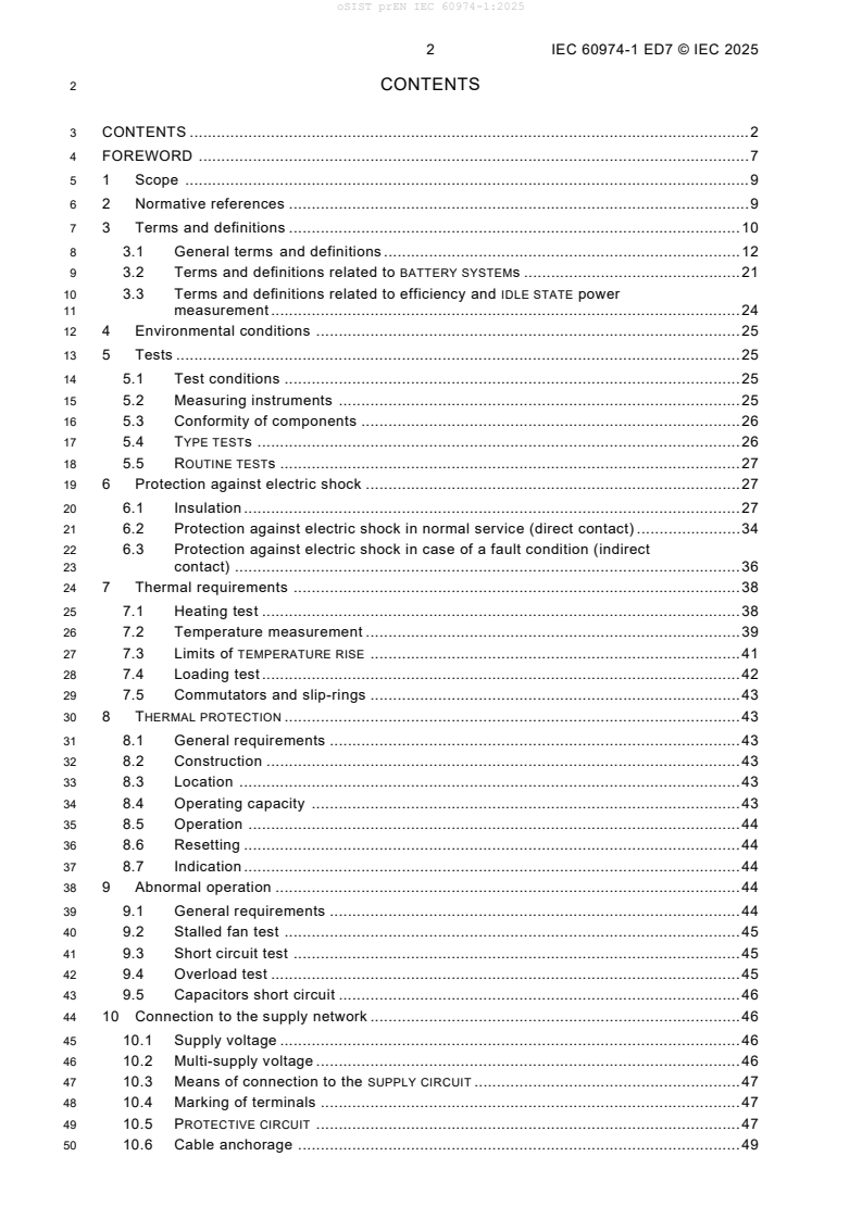
2 CONTENTS
3 CONTENTS . 2
4 FOREWORD . 7
5 1 Scope . 9
6 2 Normative references . 9
7 3 Terms and definitions . 10
8 3.1 General terms and definitions . 12
9 3.2 Terms and definitions related to BATTERY SYSTEMs . 21
10 3.3 Terms and definitions related to efficiency and IDLE STATE power
11 measurement . 24
12 4 Environmental conditions . 25
13 5 Tests . 25
14 5.1 Test conditions . 25
15 5.2 Measuring instruments . 25
16 5.3 Conformity of components . 26
17 5.4 TYPE TESTs . 26
18 5.5 ROUTINE TESTs . 27
19 6 Protection against electric shock . 27
20 6.1 Insulation . 27
21 6.2 Protection against electric shock in normal service (direct contact) . 34
22 6.3 Protection against electric shock in case of a fault condition (indirect
23 contact) . 36
24 7 Thermal requirements . 38
25 7.1 Heating test . 38
26 7.2 Temperature measurement . 39
27 7.3 Limits of TEMPERATURE RISE . 41
28 7.4 Loading test . 42
29 7.5 Commutators and slip-rings . 43
30 8 THERMAL PROTECTION . 43
31 8.1 General requirements . 43
32 8.2 Construction . 43
33 8.3 Location . 43
34 8.4 Operating capacity . 43
35 8.5 Operation . 44
36 8.6 Resetting . 44
37 8.7 Indication . 44
38 9 Abnormal operation . 44
39 9.1 General requirements . 44
40 9.2 Stalled fan test . 45
41 9.3 Short circuit test . 45
42 9.4 Overload test . 45
43 9.5 Capacitors short circuit . 46
44 10 Connection to the supply network . 46
45 10.1 Supply voltage . 46
46 10.2 Multi-supply voltage . 46
47 10.3 Means of connection to the SUPPLY CIRCUIT . 47
48 10.4 Marking of terminals . 47
49 10.5 PROTECTIVE CIRCUIT . 47
50 10.6 Cable anchorage . 49
oSIST prEN IEC 60974-1:2025
IEC 60974-1 ED7 © IEC 2025 3
51 10.7 Inlet openings . 50
52 10.8 SUPPLY CIRCUIT on/off switching device . 50
53 10.9 Supply cables . 51
54 10.10 Supply coupling device (attachment plug) . 51
55 11 Output . 51
56 11.1 RATED NO-LOAD VOLTAGE . 51
57 11.2 TYPE TEST values of the CONVENTIONAL LOAD VOLTAGE . 54
58 11.3 Mechanical switching devices used to adjust output . 55
59 11.4 WELDING CIRCUIT connections . 55
60 11.5 Power supply to external devices connected to the WELDING CIRCUIT . 57
61 11.6 Auxiliary power supply . 57
62 11.7 Welding cables . 57
63 12 CONTROL CIRCUITs . 58
64 12.1 General requirement . 58
65 12.2 Isolation of CONTROL CIRCUITs . 58
66 12.3 WORKING VOLTAGEs of remote CONTROL CIRCUITs . 58
67 13 HAZARD REDUCING DEVICE . 58
68 13.1 General requirements . 58
69 13.2 Types of HAZARD REDUCING DEVICES . 59
70 13.3 Requirements for HAZARD REDUCING DEVICEs . 59
71 14 Mechanical provisions . 60
72 14.1 General requirements . 60
73 14.2 Enclosure . 60
74 14.3 Handling means . 60
75 14.4 Drop withstand . 61
76 14.5 Tilting stability . 62
77 15 RATING PLATE . 62
78 15.1 General requirements . 62
79 15.2 Description . 62
80 15.3 Contents . 63
81 15.4 Tolerances . 66
82 15.5 Direction of rotation . 66
83 16 Adjustment of the output . 66
84 16.1 Type of adjustment . 66
85 16.2 Marking of the adjusting device . 66
86 16.3 Indication of current or voltage control . 67
87 17 Instructions and markings . 67
88 17.1 Instructions . 67
89 17.2 Markings . 68
90 Annex A (normative) Nominal voltages of supply networks . 70
91 Annex B (informative) Example of a combined dielectric test . 73
92 Annex C (normative) Unbalanced load in case of AC tungsten inert-gas WELDING
93 . 74
POWER SOURCES
94 C.1 General . 74
95 C.2 Unbalanced load . 74
96 C.3 Example for an unbalanced load . 75
97 Annex D (informative) Extrapolation of temperature to time of shutdown . 77
98 Annex E (normative) Construction of SUPPLY CIRCUIT terminals . 78
99 E.1 Size of terminals . 78
100 E.2 Connections at the terminals . 78
oSIST prEN IEC 60974-1:2025
4 IEC 60974-1 ED7 © IEC 2025
101 E.3 Construction of the terminals . 79
102 E.4 Fixing of the terminals . 79
103 Annex F (informative) Cross-reference to non-SI units . 80
104 Annex G (normative) Suitability of supply network for the measurement of the true
105 RMS value of the supply current . 81
106 Annex H (informative) Plotting of STATIC CHARACTERISTICS . 82
107 H.1 General . 82
108 H.2 Method . 82
109 H.3 Analysis of the results . 82
110 Annex I (normative) Test methods for a 10 Nm impact . 83
111 I.1 Pendulum impact hammer . 83
112 I.2 Free fall spherical steel weight . 83
113 Annex J (normative) Thickness of sheet metal for enclosures . 85
114 Annex K (informative) Examples of RATING PLATES . 87
115 Annex L (informative) Graphical symbols for arc welding equipment . 94
116 L.1 General . 94
117 L.2 Use of symbols . 94
118 L.3 Symbols . 94
119 L.4 Examples of combinations of symbols . 111
120 L.5 Examples of control panels . 113
121 Annex M (informative) Efficiency and IDLE STATE power measurement . 116
122 M.1 General conditions for measurement . 116
123 M.2 Measurements . 117
124 M.3 Test report . 120
125 M.4 Test report template . 121
126 Annex N (normative) TOUCH CURRENT measurement . 124
127 Annex O (normative) Battery-powered WELDING POWER SOURCES . 130
128 O.1 General . 130
129 O.4 Environmental conditions . 131
130 O.5 Tests . 131
131 O.6 Protection against electric shock . 132
132 O.7 Thermal requirements . 135
133 O.8 THERMAL PROTECTION . 137
134 O.9 Abnormal operation . 137
135 O.10 Connection to the supply network . 141
136 O.14 Mechanical provisions . 142
137 O.15 RATING PLATE . 144
138 O.17 Instructions and markings . 145
139 Annex P (normative) Isolation resistance measurements for BATTERY VOLTAGE CLASS B
140 electric circuits . 147
141 Bibliography . 149
143 Figure 1 – Flow chart for conformity methods of 5.3 . 26
144 Figure 2 – Example of insulation configuration for CLASS I EQUIPMENT . 28
145 Figure 3 – Measurement of WELDING CIRCUIT TOUCH CURRENT . 35
146 Figure 4 – Measurement of TOUCH CURRENT in normal condition . 36
147 Figure 5 – Measurement of RMS values . 53
148 Figure 6 – Measurement of peak values . 54
149 Figure 7 – Principle of the RATING PLATE . 63
oSIST prEN IEC 60974-1:2025
IEC 60974-1 ED7 © IEC 2025 5
150 Figure B.1 – Combined high-voltage transformers . 73
151 Figure C.1 – Voltage and current during AC tungsten inert-gas welding . 74
152 Figure C.2 – Unbalanced voltage during AC tungsten inert-gas welding . 75
153 Figure C.3 – AC WELDING POWER SOURCE with unbalanced load . 75
154 Figure I.1 – Test set-up . 83
155 Figure K.1 – Single-phase transformer . 87
156 Figure K.2 – Three-phase rotating frequency converter . 88
157 Figure K.3 – Subdivided RATING PLATE: single-/three-phase transformer rectifier . 89
158 Figure K.4 – Engine-generator-rectifier . 90
159 Figure K.5 – Single-/three-phase inverter type . 91
160 Figure K.6 – Battery-powered WELDING POWER SOURCE with INTEGRAL BATTERY . 92
161 Figure K.7 – Battery-powered WELDING POWER SOURCE with detachable / separable
162 BATTERY . 93
163 Figure L.1 – Input voltage power switch . 114
164 Figure L.2 – Arc force control potentiometer . 114
165 Figure L.3 – Remote receptacle and selector switches . 114
166 Figure L.4 – Terminals with inductance selector for MIG/MAG welding. 114
167 Figure L.5 – Process switch (MMA, TIG, MIG) . 115
168 Figure L.6 – Selector switch on AC/DC equipment . 115
169 Figure L.7 – Panel indicator lights (overheat, fault, arc striking, output voltage) . 115
170 Figure L.8 – Setting pulsing parameters using digital display . 115
171 Figure M.1 – Measurement procedure . 120
172 Figure N.1 – Measuring network, TOUCH CURRENT weighted for perception or
173 startle-reaction . 124
174 Figure N.2 – Measuring network, TOUCH CURRENT weighted for letgo-immobilization . 125
175 Figure N.3 – Diagram for TOUCH CURRENT measurement on fault condition at operating
176 temperature for single-phase connection of appliances other than those of CLASS II . 127
177 Figure N.4 – Diagram for TOUCH CURRENT measurement on fault condition for three-
178 phase four-wire system connection of appliances other than those of CLASS II . 129
179 Figure O.1 – Marking of BATTERY VOLTAGE CLASS B electric components . 146
180 Figure P.1 – Example for the measurement of the isolation resistance . 147
182 Table 1 – Alphabetical list of terms . 11
183 Table 2 – Minimum CLEARANCES for overvoltage category III . 29
184 Table 3 – Minimum CREEPAGE DISTANCES . 31
185 Table 4 – Insulation resistance . 32
186 Table 5 – Minimum dielectric test voltages . 33
187 Table 6 – Minimum distance through insulation . 36
188 Table 7 – Temperature limits for windings, commutators and slip-rings . 41
189 Table 8 – Temperature limits for external surfaces . 42
190 Table 9 – Cross-section of the output short-circuit conductor . 45
191 Table 10 – Current and time requirements for PROTECTIVE CIRCUITS . 48
192 Table 11 – Minimum cross-sectional area of the external protective copper conductor . 48
193 Table 12 – Verification of continuity of the PROTECTIVE CIRCUIT . 49
194 Table 13 – Pull. 49
195 Table 14 – Summary of allowable RATED NO-LOAD VOLTAGES . 53
oSIST prEN IEC 60974-1:2025
6 IEC 60974-1 ED7 © IEC 2025
196 Table 15 – HAZARD REDUCING DEVICE requirements . 58
197 Table A.1 – Nominal voltages for supply networks with protective overvoltage control . 70
198 Table A.2 – Single-phase three-wire or two-wire AC or DC systems . 71
199 Table A.3 – Three-phase four-wire or three-wire AC systems . 72
200 Table E.1 – Range of conductor dimensions to be accepted by the SUPPLY CIRCUIT
201 terminals . 78
202 Table F.1 – Cross-reference for mm to American wire gauge (AWG) . 80
203 Table I.1 – Angle of rotation θ to obtain 10 Nm impact . 83
204 Table I.2 – Mass of the free fall weight and height of the free fall . 84
205 Table J.1 – Minimum thickness of sheet metal for steel enclosures . 85
206 Table J.2 – Minimum thickness of sheet metal for enclosures of aluminium, brass or
207 copper . 86
208 Table L.1 – Letters used as symbols . 95
209 Table M.1 – Typical nominal electricity supply details for some regions . 116
210 Table M.2 – Load conditions for the ARC WELDING POWER SOURCE . 118
211 Table M.3 – Required reported data (measured and calculated). 121
oSIST prEN IEC 60974-1:2025
IEC 60974-1 ED7 © IEC 2025 7
214 INTERNATIONAL ELECTROTECHNICAL COMMISSION
215 ____________
217 ARC WELDING EQUIPMENT –
219 Part 1: Welding power sources
221 FOREWORD
222 1) The International Electrotechnical Commission (IEC) is a worldwide organization for standardization comprising
223 all national electrotechnical committees (IEC National Committees). The object of IEC is to promote international
224 co-operation on all questions concerning standardization in the electrical and electronic fields. To this end and
225 in addition to other activities, IEC publishes International Standards, Technical Specifications, Technical Reports,
226 Publicly Available Specifications (PAS) and Guides (hereafter referred to as “IEC Publication(s)”). Their
227 preparation is entrusted to technical committees; any IEC National Committee interested in the subject dealt with
228 may participate in this preparatory work. International, governmental and non-governmental organizations liaising
229 with the IEC also participate in this preparation. IEC collaborates closely with the International Organization for
230 Standardization (ISO) in accordance with conditions determined by agreement between the two organizations.
231 2) The formal decisions or agreements of IEC on technical matters express, as nearly as possible, an international
232 consensus of opinion on the relevant subjects since each technical committee has representation from all
233 interested IEC National Committees.
234 3) IEC Publications have the form of recommendations for international use and are accepted by IEC National
235 Committees in that sense. While all reasonable efforts are made to ensure that the technical content of IEC
236 Publications is accurate, IEC cannot be held responsible for the way in which they are used or for any
237 misinterpretation by any end user.
238 4) In order to promote international uniformity, IEC National Committees undertake to apply IEC Publications
239 transparently to the maximum extent possible in their national and regional publications. Any divergence between
240 any IEC Publication and the corresponding national or regional publication shall be clearly indicated in the latter.
241 5) IEC itself does not provide any attestation of conformity. Independent certification bodies provide conformity
242 assessment services and, in some areas, access to IEC marks of conformity. IEC is not responsible for any
243 services carried out by independent certification bodies.
244 6) All users should ensure that they have the latest edition of this publication.
245 7) No liability shall attach to IEC or its directors, employees, servants or agents including individual experts and
246 members of its technical committees and IEC National Committees for any personal injury, property damage or
247 other damage of any nature whatsoever, whether direct or indirect, or for costs (including legal fees) and
248 expenses arising out of the publication, use of, or reliance upon, this IEC Publication or any other IEC
249 Publications.
250 8) Attention is drawn to the Normative references cited in this publication. Use of the referenced publications is
251 indispensable for the correct application of this publication.
252 9) Attention is drawn to the possibility that some of the elements of this IEC Publication may be the subject of patent
253 rights. IEC shall not be held responsible for identifying any or all such patent rights.
254 IEC 60974-1 has been prepared by IEC technical committee 26: Electric welding. It is an
255 International Standard.
256 This seventh edition cancels and replaces the sixth edition published in 2021. This edition
257 constitutes a technical revision.
258 This edition includes the following significant technical changes with respect to the previous
259 edition:
260 a) New terms and definitions to clause 3.1 added;
261 b) Verbal form changes ‘may’ to ‘can’ of edition 6 introduced at FDIS reviewed and reverted
262 where necessary;
263 c) Deletion of Notes relating to (EU) 2019/1784 in clause 3.3.2, 15.3, 16.3.3 and M.1.1;
264 d) Type Tests requirements in clause 5.4 modified;
265 e) Note to CLEARANCE verification with AC or DC voltage in clause 6.1.2 added;
266 f) Editorial adjustment of Table 3 Minimum CREEPAGE DISTANCES to
267 IEC 60664-1:2020/AMD1:2025;
268 g) Capacitor short circuit test procedure in clause 9.5 refined;
269 h) Voltage reducing device test procedure in clause 13.2.1 reworded for clarification;
oSIST prEN IEC 60974-1:2025
8 IEC 60974-1 ED7 © IEC 2025
270 i) Duty cycle requirements on RATING PLATE in clause 15.3 b) reworded for clarification;
271 j) Abnormal operation test requirements in O.9.1 aligned to 9.1;
272 k) New Annex P added.
273 The text of this International Standard is based on the following documents:
FDIS Report on voting
26/xxx/FDIS 26/xxx/RVD
275 Full information on the voting for its approval can be found in the report on voting indicated in
276 the above table.
277 The language used for the development of this International Standard is English.
278 This document was drafted in accordance with ISO/IEC Directives, Part 2, and developed in
279 accordance with ISO/IEC Directives, Part 1 and ISO/IEC Directives, IEC Supplement, available
280 at www.iec.ch/members_experts/refdocs. The main document types developed by IEC are
281 described in greater detail at www.iec.ch/standardsdev/publications.
282 In this document, the following print types are used:
283 – conformity statements: in italic type.
284 – terms used throughout this document which have been defined in Clause 3: SMALL ROMAN
285 CAPITALS.
286 A list of all parts of the IEC 60974 series can be found, under the general title Arc welding
287 equipment, on the IEC website.
288 The committee has decided that the contents of this document will remain unchanged until the
289 stability date indicated on the IEC website under webstore.iec.ch in the data related to the
290 specific document. At this date, the document will be
291 • reconfirmed,
292 • withdrawn,
293 • replaced by a revised edition, or
294 • amended.
IMPORTANT – The 'colour inside' logo on the cover page of this publication indicates
that it contains colours which are considered to be useful for the correct understanding
of its contents. Users should therefore print this document using a colour printer.
oSIST prEN IEC 60974-1:2025
IEC 60974-1 ED7 © IEC 2025 9
298 ARC WELDING EQUIPMENT –
300 Part 1: Welding power sources
304 1 Scope
305 This part of IEC 60974 is applicable to power sources for arc welding and allied processes
306 designed for INDUSTRIAL AND PROFESSIONAL USE, and supplied by a voltage not exceeding
307 1 000 V, BATTERY supplied or driven by mechanical means.
308 This document specifies safety and performance requirements of WELDING POWER SOURCES and
309 PLASMA CUTTING SYSTEMS.
310 This document is not applicable to limited duty arc welding and cutting power sources which
311 are designed mainly for use by layperson and designed in accordance with IEC 60974-6.
312 This document includes requirements for battery-powered WELDING POWER SOURCES and
313 BATTERY packs, which are given in Annex O.
314 This document is not applicable to testing of power sources during periodic maintenance or
315 after repair.
316 NOTE 1 Typical allied processes are electric arc cutting and arc spraying.
317 NOTE 2 AC systems having a nominal voltage between 100 V and 1 000 V are given in Table 1 of IEC 60038:2009.
318 NOTE 3 This document does not include electromagnetic compatibility (EMC) requirements.
319 2 Normative references
320 The following documents are referred to in the text in such a way that some or all of their content
321 constitutes requirements of this document. For dated references, only the edition cited applies.
322 For undated references, the latest edition of the referenced document (including any
323 amendments) applies.
324 IEC 60245-6, Rubber insulated cables – Rated voltages up to and including 450/750 V – Part 6:
325 Arc welding electrode cables
326 IEC 60445, Basic and safety principles for man-machine interface, marking and identification –
327 Identification of equipment terminals, conductor terminations and conductors
328 IEC 60529, Degrees of protection provided by enclosures (IP Code)
329 IEC 60664-1:2020, Insulation coordination for equipment within low-voltage systems – Part 1:
330 Principles, requirements and tests
331 IEC 60664-1:2020/AMD1:2025
332 IEC 60664-3, Insulation coordination for equipment within low-voltage systems – Part 3: Use of
333 coating, potting or moulding for protection against pollution
334 IEC 60695-11-10, Fire hazard testing – Part 11-10: Test flames – 50 W horizontal and vertical
335 flame test methods
336 IEC 60974-7, Arc welding equipment – Part 7: Torches
oSIST prEN IEC 60974-1:2025
10 IEC 60974-1 ED7 © IEC 2025
337 IEC 60974-10, Arc welding equipment – Part 10: Electromagnetic compatibility (EMC)
338 requirements
339 IEC 61140, Protection against electric shock – Common aspects for installation and equipment
340 IEC 61558-2-4, Safety of transformers, reactors, power supply units and similar products for
341 supply voltages up to 1 100 V – Part 2-4: Particular requirements and tests for isolating
342 transformers and power supply units incorporating isolating transformers
343 IEC 61558-2-6, Safety of transformers, reactors, power supply units and similar products for
344 supply voltages up to 1 100 V – Part 2-6: Particular requirements and tests for safety isolating
345 transformers and power supply units incorporating safety isolating transformers
346 IEC 62133-1:2017, Secondary cells and batteries containing alkaline or other non-acid
347 electrolytes – Safety requirements for portable sealed secondary cells, and for batteries made
348 from them, for use in portable applications – Part 1: Nickel systems
349 IEC 62133-2:2017, Secondary cells and batteries containing alkaline or other non-acid
350 electrolytes – Safety requirements for portable sealed secondary lithium cells, and for batteries
351 made from them, for use in portable applications – Part 2: Lithium systems
352 IEC 62133-2:2017/AMD1:2021
353 IEC 62301:2011, Household electrical appliances – Measurement of standby power
354 ISO 7010:2019, Graphical symbols – Safety colours and safety signs – Registered safety signs
355 ISO 7010:2019/Amd 1:2020
356 ISO 7010:2019/Amd 2:2020
357 ISO 7010:2019/Amd 3:2021
358 ISO 7010:2019/Amd 4:2021
359 ISO 7010:2019/Amd 5:2022
360 ISO 7010:2019/Amd 6:2022
361 ISO 7010:2019/Amd 7:2023
362 ISO 7010:2019/Amd 8:2024
363 3 Terms and definitions
364 For the purposes of this document, the following terms and definitions apply.
365 ISO and IEC maintain terminological databases for use in standardization at the following
366 addresses:
367 • IEC Electropedia: available at http://www.electropedia.org/
368 • ISO Online browsing platform: available at http://www.iso.org/obp
369 Table 1 provides an alphabetical cross-reference listing of terms.
oSIST prEN IEC 60974-1:2025
IEC 60974-1 ED7 © IEC 2025 11
370 Table 1 – Alphabetical list of terms
Term Term Term Term Term Term
number number number
AC, qualifier 3.1.68 expert 3.1.3 rated reduced no-load 3.1.27
voltage
active power 3.3.3 explosion 3.2.23 rated supply current 3.1.30
ancillary equipment 3.1.70 fixed installation 3.1.62 rated supply frequency 3.3.1
apparent power 3.3.4 flat characteristic 3.1.9 rated supply voltage 3.1.29
basic insulation 3.1.50 fully charged cell 3.2.10 rated switched no-load 3.1.28
voltage
basic protection 3.2.18 fully discharged cell 3.2.11 rated value 3.1.21
battery 3.2.1 functional insulation 3.1.65 rating plate 3.1.22
battery system 3.2.5 general purpose 3.2.12 reinforced insulation 3.1.53
batteries
battery voltage class A 3.2.19 hazard reducing device 3.1.47 remote control 3.1.60
battery voltage class B 3.2.20 idle state 3.1.66 routine test 3.1.6
C rate 3.2.6 industrial and 3.1.2 safety extra-low voltage 3.1.56
professional use
cell 3.2.7 instructed person 3.1.4 separable battery pack 3.2.4
charger 3.2.8 integral battery 3.2.2 single-fault condition 3.1.61
charging system 3.2.9 load voltage 3.1.14 specified operating 3.2.14
region
charring 3.2.21 material group 3.1.42 specified operating 3.2.14.1
region for charging
class I equipment 3.1.48 maximum charging 3.2.13 static characteristic 3.1.10
current
class II equipment 3.1.49 maximum effective 3.1.33 supplementary 3.1.51
supply current insulation
class of insulation 3.1.64 micro-environment 3.1.41 supply circuit 3.1.57
clearance 3.1.38 no-load voltage 3.1.15 temperature rise 3.1.43
consecutive operating
3.2.22 non-operating state 3.1.67 thermal equilibrium 3.1.44
cycle
control circuit 3.1.12 plasma cutting power 3.1.55 thermal protection 3.1.45
source
conventional load 3.1.18 plasma cutting system 3.1.54 total harmonic distortion 3.3.6
conventional load 3.1.20 pollution degree 3.1.40 touch current 3.1.59
voltage
conventional value 3.1.16 power factor 3.3.5 type test 3.1.5
conventional welding 3.1.17 protective circuit 3.1.63 upper limit charging 3.2.15
condition voltage
conventional welding 3.1.19 rated idle speed 3.1.36 venting 3.2.16
current
creepage distance 3.1.39 rated load speed 3.1.34 visual inspection 3.1.7
DC, qualifier 3.1.69 rated maximum supply 3.1.32 welding circuit 3.1.11
current
detachable battery pack 3.2.3 rated maximum welding 3.1.24 welding current 3.1.13
current
double insulation 3.1.52 rated minimum welding 3.1.25 welding power source 3.1.1
current
drooping characteristic 3.1.8 rated no-load speed 3.1.35 welding power source 3.3.2
efficiency
duty cycle 3.1.37 rated no-load supply 3.1.31 working voltage 3.1.58
current
electronic component 3.2.17 rated no-load voltage 3.1.26
oSIST prEN IEC 60974-1:2025
12 IEC 60974-1 ED7 © IEC 2025
Term Term Term Term Term Term
number number number
environment with 3.1.46 rated output 3.1.23
increased risk of electric
shock
372 3.1 General terms and definitions
373 3.1.1
374 welding power source
375 arc welding power source
376 equipment for supplying current and voltage and having the required characteristics suitable for
377 arc welding and allied processes
378 Note 1 to entry: A WELDING POWER SOURCE can also supply services to other equipment and auxiliaries for example
379 auxiliary power, cooling liquid, consumable arc welding electrode and gas to shield the arc and the welding area.
380 [SOURCE: IEC 60050-851:20xx, 851-13-01]
381 3.1.2
382 industrial and professional use
383 use intended only for EXPERTS or INSTRUCTED PERSONS
384 [SOURCE: IEC 60050-851:2008, 851-11-12]
385 3.1.3
386 expert
387 person who can judge the work assigned and recognize possible hazards on the basis of
388 professional training, knowledge, experience and knowledge of the relevant equipment
389 Note 1 to entry: Several years of practice in the relevant technical field can be taken into consideration in
390 assessment of professional training.
391 [SOURCE: IEC 60050-851:20xx, 851-11-10]
392 3.1.4
393 instructed person
394 person informed about the tasks assigned and about the possible hazards involved in neglectful
395 behaviour
396 Note 1 to entry: If necessary, the person has undergone some training.
397 [SOURCE: IEC 60050-851:2008, 851-11-13]
398 3.1.5
399 type test
400 test of one or more devices made to a given design to check if these devices comply with the
401 requirements of the standard concerned
402 [SOURCE: IEC 60050-851:2008, 851-12-05]
403 3.1.6
404 routine test
405 test made on each individual device during or after manufacture to check if it complies with the
406 requirements of the standard concerned or the criteria speci
...