

IEC/IEEE 62395-1:2024
(Main)Electrical resistance trace heating systems for industrial and commercial applications - Part 1: General and testing requirements
- Abstract
IEC/IEEE 62395-1:2024 specifies requirements for electrical resistance trace heating systems and includes general test requirements.
This first edition cancels and replaces the second edition published in 2013. This edition constitutes a technical revision.
This edition includes the following significant technical changes, apart from general revisions of IEC 62395-1 and harmonization with IEEE 515 [1] and IEEE 515.1 [2], with respect to the previous edition:
a) Added control and monitoring requirements for fire sprinkler systems and safety showers.
b) Provided a supplemental ice bath method for verification of rated output.
c) Provided constructional and type test requirements for glands used to terminate heating devices to an exposed enclosure.
- Status
- Published
- Publication Date
- 26-Jun-2024
- Technical Committee
- TC 27 - Industrial electroheating and electromagnetic processing
- Drafting Committee
- JWG 34 - TC 27/JWG 34
- Current Stage
- PPUB - Publication issued
- Start Date
- 27-Jun-2024
- Completion Date
- 14-Jun-2024
Buy Documents


IEC/IEEE 62395-1:2024 - Electrical resistance trace heating systems for industrial and commercial applications - Part 1: General and testing requirements Released:6/27/2024
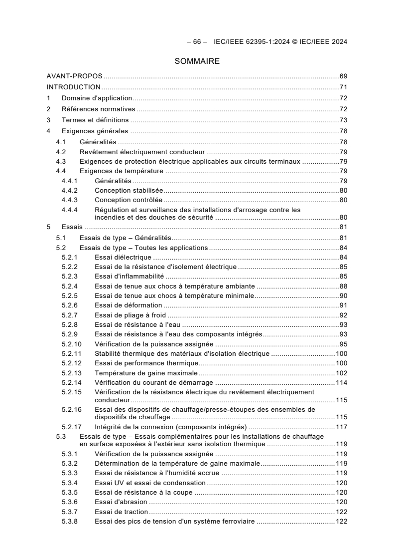
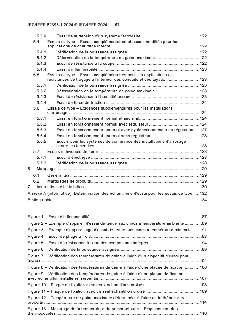
IEC/IEEE 62395-1:2024 - Systèmes de traçage par résistance électrique pour applications industrielles et commerciales - Partie 1: Exigences générales et d'essai
Overview
IEC/IEEE 62395-1:2024 is an international standard developed by the IEC and IEEE that specifies the general requirements and testing procedures for electrical resistance trace heating systems used in industrial and commercial applications. This updated first edition revises and replaces the previous 2013 edition, harmonizing requirements with other key standards such as IEEE 515 and IEEE 515.1. The standard outlines requirements for both factory-fabricated and field-assembled trace heating units, including surface heaters, heater panels, and their associated terminations and controls.
This document helps ensure trace heating systems are safe, reliable, and robust, supporting their efficient use in precise heating applications across a variety of sectors.
Key Topics
- Scope and Applicability: Defines electrical resistance trace heating systems and their components, including installation and termination requirements, for industrial and commercial use.
- Testing Requirements: Details a range of general and specific type tests to verify product safety and performance across different application conditions.
- Control and Monitoring: Introduces expanded requirements for control and monitoring, specifically for critical safety applications such as fire sprinkler systems and safety showers.
- Verification Methods: Includes a supplemental ice bath method to verify rated heating output, supporting consistent performance validation.
- Component Testing: Addresses construction and type testing for glands used to terminate heating devices at exposed enclosures, improving installation safety.
- Comprehensive Definitions: Provides clear definitions for system components and terms, supporting consistency in product development, installation, and maintenance.
- Marking and Documentation: Specifies requirements for product marking and system documentation to ensure safe installation and user understanding.
Applications
Electrical resistance trace heating systems covered by IEC/IEEE 62395-1:2024 are widely used in:
- Pipe Freeze Protection: Preventing water or process fluid pipes from freezing in industrial plants and commercial buildings.
- Temperature Maintenance: Keeping process piping, tanks, and vessels at target temperatures required for safe and efficient operation.
- Fire Safety Systems: Ensuring the functionality of fire sprinkler pipes and safety showers in cold or variable environments, with newly specified control and monitoring protocols.
- Surface Heating: Providing heat for surfaces such as platforms, walkways, or equipment panels to prevent ice, maintain process temperatures, or support surface processes.
- Construction and Field Assembly Support: Enabling offsite or onsite assembly to fit a variety of installation needs in new and retrofit projects.
The standard emphasizes that all installations should be handled by trained personnel under qualified supervision, ensuring safety and compliance with system requirements.
Related Standards
Implementing IEC/IEEE 62395-1:2024 may also involve reference to several related international standards, particularly when specifying, installing, or maintaining trace heating systems:
- IEEE 515 / IEEE 515.1: Requirements for electric heating systems for pipelines and vessels.
- IEC/IEEE 62395-2:2024: Application guide covering system design, installation, and maintenance for trace heating systems (companion to Part 1).
- IEC 60519-1: Safety in installations for electroheating and electromagnetic processing.
- IEC 60529: Degrees of protection by enclosures (IP Code).
- Fire Safety Testing Standards: Such as ISO 7240-2 and ASTM specifications for control units and flame tests.
- IEC/IEEE 60079-30-1 & 60079-30-2: For trace heating systems in potentially explosive atmospheres, which are outside the scope of IEC/IEEE 62395-1:2024.
IEC/IEEE 62395-1:2024 is essential for manufacturers, system designers, installers, and facility managers seeking compliance, safety, and optimal performance for electrical resistance trace heating systems in industrial and commercial environments. Implementing this standard supports effective risk management, regulatory compliance, and operational reliability in trace heating applications.
Relations
- Effective Date
- 05-Sep-2023
Buy Documents
IEC/IEEE 62395-1:2024 - Electrical resistance trace heating systems for industrial and commercial applications - Part 1: General and testing requirements Released:6/27/2024
IEC/IEEE 62395-1:2024 - Systèmes de traçage par résistance électrique pour applications industrielles et commerciales - Partie 1: Exigences générales et d'essai
Get Certified
Connect with accredited certification bodies for this standard

DVS-ZERT GmbH
German welding certification society.
CARES (UK Certification Authority for Reinforcing Steels)
UK certification for reinforcing steels and construction.
EWF/IIW (European/International Welding Federation)
International welding personnel certification.
Sponsored listings
Frequently Asked Questions
IEC/IEEE 62395-1:2024 is a standard published by the International Electrotechnical Commission (IEC). Its full title is "Electrical resistance trace heating systems for industrial and commercial applications - Part 1: General and testing requirements". This standard covers: IEC/IEEE 62395-1:2024 specifies requirements for electrical resistance trace heating systems and includes general test requirements. This first edition cancels and replaces the second edition published in 2013. This edition constitutes a technical revision. This edition includes the following significant technical changes, apart from general revisions of IEC 62395-1 and harmonization with IEEE 515 [1] and IEEE 515.1 [2], with respect to the previous edition: a) Added control and monitoring requirements for fire sprinkler systems and safety showers. b) Provided a supplemental ice bath method for verification of rated output. c) Provided constructional and type test requirements for glands used to terminate heating devices to an exposed enclosure.
IEC/IEEE 62395-1:2024 specifies requirements for electrical resistance trace heating systems and includes general test requirements. This first edition cancels and replaces the second edition published in 2013. This edition constitutes a technical revision. This edition includes the following significant technical changes, apart from general revisions of IEC 62395-1 and harmonization with IEEE 515 [1] and IEEE 515.1 [2], with respect to the previous edition: a) Added control and monitoring requirements for fire sprinkler systems and safety showers. b) Provided a supplemental ice bath method for verification of rated output. c) Provided constructional and type test requirements for glands used to terminate heating devices to an exposed enclosure.
IEC/IEEE 62395-1:2024 is classified under the following ICS (International Classification for Standards) categories: 25.180.10 - Electric furnaces. The ICS classification helps identify the subject area and facilitates finding related standards.
IEC/IEEE 62395-1:2024 has the following relationships with other standards: It is inter standard links to IEC 62395-1:2013. Understanding these relationships helps ensure you are using the most current and applicable version of the standard.
IEC/IEEE 62395-1:2024 is available in PDF format for immediate download after purchase. The document can be added to your cart and obtained through the secure checkout process. Digital delivery ensures instant access to the complete standard document.
Standards Content (Sample)
IEC/IEEE 62395-1 ®
Edition 1.0 2024-06
INTERNATIONAL
STANDARD
colour
inside
Electrical resistance trace heating systems for industrial and commercial
applications –
Part 1: General and testing requirements
All rights reserved. Unless otherwise specified, no part of this publication may be reproduced or utilized in any form or
by any means, electronic or mechanical, including photocopying and microfilm, without permission in writing being
secured. Requests for permission to reproduce should be addressed to either IEC at the address below or IEC’s
member National Committee in the country of the requester or from IEEE.
IEC Secretariat Institute of Electrical and Electronics Engineers, Inc.
3, rue de Varembé 3 Park Avenue
CH-1211 Geneva 20 New York, NY 10016-5997
Switzerland United States of America
Tel.: +41 22 919 02 11 stds.ipr@ieee.org
info@iec.ch www.ieee.org
www.iec.ch
About the IEC
The International Electrotechnical Commission (IEC) is the leading global organization that prepares and publishes
International Standards for all electrical, electronic and related technologies.
About the IEEE
IEEE is the world’s largest professional association dedicated to advancing technological innovation and excellence for the
benefit of humanity. IEEE and its members inspire a global community through its highly cited publications, conferences,
technology standards, and professional and educational activities.
About IEC/IEEE publications
The technical content of IEC/IEEE publications is kept under constant review by the IEC and IEEE. Please make sure that
you have the latest edition, a corrigendum or an amendment might have been published.
IEC publications search - webstore.iec.ch/advsearchform IEC Products & Services Portal - products.iec.ch
The advanced search enables to find IEC publications by a Discover our powerful search engine and read freely all the
variety of criteria (reference number, text, technical publications previews, graphical symbols and the glossary.
committee, …). It also gives information on projects, replaced With a subscription you will always have access to up to date
and withdrawn publications. content tailored to your needs.
IEC Just Published - webstore.iec.ch/justpublished
Electropedia - www.electropedia.org
Stay up to date on all new IEC publications. Just Published
The world's leading online dictionary on electrotechnology,
details all new publications released. Available online and once
containing more than 22 500 terminological entries in English
a month by email.
and French, with equivalent terms in 25 additional languages.
Also known as the International Electrotechnical Vocabulary
IEC Customer Service Centre - webstore.iec.ch/csc
(IEV) online.
If you wish to give us your feedback on this publication or need
further assistance, please contact the Customer Service
Centre: sales@iec.ch.
IEC/IEEE 62395-1 ®
Edition 1.0 2024-06
INTERNATIONAL
STANDARD
colour
inside
Electrical resistance trace heating systems for industrial and commercial
applications –
Part 1: General and testing requirements
INTERNATIONAL
ELECTROTECHNICAL
COMMISSION
ICS 25.180.10 ISBN 978-2-8322-9002-6
– 2 – IEC/IEEE 62395-1:2024 © IEC/IEEE 2024
CONTENTS
FOREWORD . 5
INTRODUCTION . 7
1 Scope . 8
2 Normative references . 8
3 Terms and definitions . 9
4 General requirements . 14
4.1 General . 14
4.2 Electrically conductive covering . 15
4.3 Electrical circuit protection requirements for branch circuits . 15
4.4 Temperature requirements . 15
4.4.1 General . 15
4.4.2 Stabilized design . 15
4.4.3 Controlled design . 15
4.4.4 Controls and monitoring for fire sprinkler systems and safety showers . 16
5 Testing . 16
5.1 Type tests – General . 16
5.2 Type tests – All applications . 19
5.2.1 Dielectric test . 19
5.2.2 Electrical insulation resistance test . 20
5.2.3 Flammability test . 20
5.2.4 Room temperature impact test . 23
5.2.5 Minimum temperature impact test . 25
5.2.6 Deformation test . 26
5.2.7 Cold bend test . 27
5.2.8 Water resistance test . 28
5.2.9 Integral components resistance to water test . 28
5.2.10 Verification of rated output . 29
5.2.11 Thermal stability of electrical insulating material . 33
5.2.12 Thermal performance test . 33
5.2.13 Maximum sheath temperature . 35
5.2.14 Verification of start-up current . 46
5.2.15 Verification of the electrical resistance of the electrically conductive
covering . 46
5.2.16 Test for heating device / heating device set glands - General . 47
5.2.17 Connection Integrity (integral components) . 48
5.3 Type tests – Additional tests for outdoor exposed surface heating
installations without thermal insulation . 50
5.3.1 Verification of rated output . 50
5.3.2 Determination of maximum sheath temperature . 50
5.3.3 Increased moisture resistance test . 50
5.3.4 UV and condensation test . 51
5.3.5 Resistance to cutting test . 51
5.3.6 Abrasion test . 51
5.3.7 Tension test . 52
5.3.8 Rail system voltage spike test . 52
5.3.9 Rail system over-voltage test . 53
5.4 Type tests – Additional tests and test modifications for embedded heating
applications. 53
5.4.1 Verification of rated output . 53
5.4.2 Determination of maximum sheath temperature . 53
5.4.3 Resistance to cutting test . 53
5.4.4 Flammability test . 53
5.5 Type tests – Additional tests for applications of trace heaters internal to
conduit and piping . 53
5.5.1 Verification of rated output . 53
5.5.2 Determination of maximum sheath temperature . 53
5.5.3 Increased moisture resistance test . 54
5.5.4 Pull-strength test . 54
5.6 Type tests – Additional requirements for sprinkler systems . 55
5.6.1 Normal and abnormal operation test . 55
5.6.2 Normal operation test with controller . 55
5.6.3 Abnormal operation test with controller malfunctioning. 58
5.6.4 Abnormal operation test without controller . 58
5.6.5 Testing for control systems for fire sprinkler systems . 58
5.7 Routine tests . 58
5.7.1 Dielectric test . 58
5.7.2 Verification of rated output . 59
6 Marking . 59
6.1 General . 59
6.2 Product markings . 59
7 Installation instructions . 60
Annex A (informative) Determination of test samples for type testing . 62
Bibliography . 64
Figure 1 – Flammability test . 22
Figure 2 – Example of room temperature impact test apparatus . 24
Figure 3 – Example of minimum temperature impact test apparatus . 26
Figure 4 – Cold bend test . 27
Figure 5 – Integral components resistance to water test . 28
Figure 6 – Verification of rated output . 32
Figure 7 – Verification of sheath temperatures utilizing pipe sculpture fixture . 37
Figure 8 – Verification of sheath temperatures utilizing plate fixture . 39
Figure 9 – Verification of sheath temperatures utilizing plate fixture with serpentined
sample . 40
Figure 10 – Plate fixture with two samples crossed over . 41
Figure 11 – Plate fixture with a single sample crossed over . 42
Figure 12 – Maximum sheath temperature using the product approach . 46
Figure 13 – Gland temperature measurement – location of thermocouples . 48
Figure 14 – Typical splice firm attachment apparatus . 49
Figure 15 – Abrasion test . 52
Figure 16 – Sprinkler system temperature control test – branch line arrangement . 56
– 4 – IEC/IEEE 62395-1:2024 © IEC/IEEE 2024
Figure 17 – Sprinkler system temperature control test – branch line – alternative
arrangement . 57
Figure 18 – Sprinkler system temperature control test – supply pipe arrangement . 57
Table 1 – Trace heater and surface heater types and related attributes . 17
Table 2 – Applicable tests for trace heaters, surface heaters, and integral components,
by trace heater and surface heater type . 18
Table 3 – Test voltages for the dielectric test . 19
Table 4 – Applicable test subclauses for the verification of rated output . 29
Table 5 – Pulling forces for strain relief test . 47
Table 6 – Product marking . 60
Table A.1 – Determination of test samples . 62
ELECTRICAL RESISTANCE TRACE HEATING SYSTEMS
FOR INDUSTRIAL AND COMMERCIAL APPLICATIONS –
Part 1: General and testing requirements
FOREWORD
1) The International Electrotechnical Commission (IEC) is a worldwide organization for standardization comprising
all national electrotechnical committees (IEC National Committees). The object of IEC is to promote international
co-operation on all questions concerning standardization in the electrical and electronic fields. To this end and in
addition to other activities, IEC publishes International Standards, Technical Specifications, Technical Reports,
Publicly Available Specifications (PAS) and Guides (hereafter referred to as "IEC document(s)"). Their
preparation is entrusted to technical committees; any IEC National Committee interested in the subject dealt with
may participate in this preparatory work. International, governmental and non-governmental organizations liaising
with the IEC also participate in this preparation.
IEEE Standards documents are developed within IEEE Societies and Standards Coordinating Committees of the
IEEE Standards Association (IEEE SA) Standards Board. IEEE develops its standards through a consensus
development process, approved by the American National Standards Institute, which brings together volunteers
representing varied viewpoints and interests to achieve the final product. Volunteers are not necessarily members
of IEEE and serve without compensation. While IEEE administers the process and establishes rules to promote
fairness in the consensus development process, IEEE does not independently evaluate, test, or verify the
accuracy of any of the information contained in its standards. Use of IEEE Standards documents is wholly
voluntary. IEEE documents are made available for use subject to important notices and legal disclaimers (see
https://standards.ieee.org/ipr/disclaimers.html for more information).
IEC collaborates closely with IEEE in accordance with conditions determined by agreement between the two
organizations. This Dual Logo International Standard was jointly developed by the IEC and IEEE under the terms
of that agreement.
2) The formal decisions of IEC on technical matters express, as nearly as possible, an international consensus of
opinion on the relevant subjects since each technical committee has representation from all interested IEC
National Committees. The formal decisions of IEEE on technical matters, once consensus within IEEE Societies
and Standards Coordinating Committees has been reached, is determined by a balanced ballot of materially
interested parties who indicate interest in reviewing the proposed standard. Final approval of the IEEE standards
document is given by the IEEE Standards Association (IEEE SA) Standards Board.
3) IEC/IEEE Publications have the form of recommendations for international use and are accepted by IEC National
Committees/IEEE Societies in that sense. While all reasonable efforts are made to ensure that the technical
content of IEC/IEEE Publications is accurate, IEC or IEEE cannot be held responsible for the way in which they
are used or for any misinterpretation by any end user.
4) In order to promote international uniformity, IEC National Committees undertake to apply IEC Publications
(including IEC/IEEE Publications) transparently to the maximum extent possible in their national and regional
publications. Any divergence between any IEC/IEEE Publication and the corresponding national or regional
publication shall be clearly indicated in the latter.
5) IEC and IEEE do not provide any attestation of conformity. Independent certification bodies provide conformity
assessment services and, in some areas, access to IEC marks of conformity. IEC and IEEE are not responsible
for any services carried out by independent certification bodies.
6) All users should ensure that they have the latest edition of this publication.
7) No liability shall attach to IEC or IEEE or their directors, employees, servants or agents including individual
experts and members of technical committees and IEC National Committees, or volunteers of IEEE Societies and
the Standards Coordinating Committees of the IEEE Standards Association (IEEE SA) Standards Board, for any
personal injury, property damage or other damage of any nature whatsoever, whether direct or indirect, or for
costs (including legal fees) and expenses arising out of the publication, use of, or reliance upon, this IEC/IEEE
Publication or any other IEC or IEEE Publications.
8) Attention is drawn to the normative references cited in this publication. Use of the referenced publications is
indispensable for the correct application of this publication.
9) Attention is drawn to the possibility that implementation of this IEC/IEEE Publication may require use of material
covered by patent rights. By publication of this standard, no position is taken with respect to the existence or
validity of any patent rights in connection therewith. IEC or IEEE shall not be held responsible for identifying
Essential Patent Claims for which a license may be required, for conducting inquiries into the legal validity or
scope of Patent Claims or determining whether any licensing terms or conditions provided in connection with
submission of a Letter of Assurance, if any, or in any licensing agreements are reasonable or non-discriminatory.
Users of this standard are expressly advised that determination of the validity of any patent rights, and the risk
of infringement of such rights, is entirely their own responsibility.
– 6 – IEC/IEEE 62395-1:2024 © IEC/IEEE 2024
IEC/IEEE 62395-1 has been prepared by IEC technical committee 27: Industrial electroheating
and electromagnetic processing, in cooperation with Petroleum & Chemical Industry Committee
of the IEEE Industrial Applications Society, under the IEC/IEEE Dual Logo Agreement between
IEC and IEEE. It is an International Standard.
This document is published as an IEC/IEEE Dual Logo standard.
This first edition cancels and replaces the second edition published in 2013. This edition
constitutes a technical revision.
This edition includes the following significant technical changes, apart from general revisions
of IEC 62395-1 and harmonization with IEEE 515 [1] and IEEE 515.1 [2], with respect to the
previous edition:
a) Added control and monitoring requirements for fire sprinkler systems and safety showers.
b) Provided a supplemental ice bath method for verification of rated output.
c) Provided constructional and type test requirements for glands used to terminate heating
devices to an exposed enclosure.
The text of this International Standard is based on the following IEC documents:
Draft Report on voting
27/1182A/FDIS 27/1186/RVD
Full information on the voting for its approval can be found in the report on voting indicated in
the above table.
The language used for the development of this International Standard is English.
This document was drafted in accordance with the rules given in the ISO/IEC Directives, Part 2,
available at www.iec.ch/members_experts/refdocs. The main document types developed by IEC
are described in greater detail at www.iec.ch/publications/.
A list of all parts in the IEC 62395 series, published under the general title Electrical resistance
trace heating systems for industrial and commercial applications, can be found on the IEC
website.
The IEC Technical Committee and IEEE Technical Committee have decided that the contents
of this document will remain unchanged until the stability date indicated on the IEC website
under webstore.iec.ch in the data related to the specific document. At this date, the document
will be
• reconfirmed,
• withdrawn, or
• revised.
IMPORTANT – The "colour inside" logo on the cover page of this document indicates
that it contains colours which are considered to be useful for the correct understanding
of its contents. Users should therefore print this document using a colour printer.
___________
Numbers in square brackets refer to the Bibliography.
INTRODUCTION
IEC/IEEE 62395-1 provides the essential requirements and testing appropriate to electrical
resistance trace heating equipment used in industrial and commercial applications. While some
of this work already exists in national or international standards, this document has collated
much of this existing work and added considerably to it.
IEC/IEEE 62395-2 provides detailed recommendations for the system design, installation and
maintenance of electric trace heating systems in industrial and commercial applications.
It is the objective of the IEC/IEEE 62395 series that, when in normal use, electrical trace heating
systems operate safely under their defined conditions of use, by
a) employing heaters of the appropriate construction and meeting the test criteria detailed in
IEC/IEEE 62395-1. The construction includes a metallic sheath, braid, screen or equivalent
electrically conductive covering;
b) operating at safe temperatures when designed, installed, and maintained in accordance with
IEC/IEEE 62395-2.
c) having at least the minimum levels of overcurrent and earth-fault protection required in
IEC/IEEE 62395-1 and IEC/IEEE 62395-2.
– 8 – IEC/IEEE 62395-1:2024 © IEC/IEEE 2024
ELECTRICAL RESISTANCE TRACE HEATING SYSTEMS
FOR INDUSTRIAL AND COMMERCIAL APPLICATIONS –
Part 1: General and testing requirements
1 Scope
This part of IEC/IEEE 62395 specifies requirements for electrical resistance trace heating
systems and includes general test requirements.
This document pertains to trace heating systems that can comprise either factory-fabricated or
field-assembled (work-site) units, and which can be series and parallel trace heaters or surface
heaters (heater pads and heater panels) that have been assembled and/or terminated in
accordance with the manufacturer's instructions.
This document also includes requirements for termination assemblies and control methods used
with trace heating systems.
This document provides the essential requirements and testing appropriate to electrical
resistance trace heating equipment used in industrial and commercial applications. The
products complying with this document are intended to be installed by persons who are suitably
trained in the techniques required and that only trained personnel carry out especially critical
work, such as the installation of connections and terminations. Installations are intended to be
carried out under the supervision of a qualified person who has undergone supplementary
training in electric trace heating systems.
This document does not include or provide for any applications in potentially explosive
atmospheres.
This document does not cover induction, impedance or skin effect heating.
Trace heating systems are grouped into different types of applications and the different
conditions found during and after installation necessitate different requirements for testing.
Trace heating systems are usually for a specific type of installation or application. The product
type grouping, applications and product attributes are indicated in Table 1.
NOTE Trace heating systems intended for use in explosive atmospheres are the subject of IEC/IEEE 60079-30-1
[3] and IEC/IEEE 60079-30-2 [4].
2 Normative references
The following documents are referred to in the text in such a way that some or all of their content
constitutes requirements of this document. For dated references, only the edition cited applies.
For undated references, the latest edition of the referenced document (including any
amendments) applies.
IEC 60519-1, Safety in installations for electroheating and electromagnetic processing – Part 1:
General requirements
IEC 60529, Degrees of protection provided by enclosures (IP Code)
IEC 60695-11-3:2012, Fire hazard testing – Part 11-3: Test flames – 500 W flames – Apparatus
and confirmational test methods
IEC/IEEE 62395-2:2024, Electrical resistance trace heating systems for industrial and
commercial applications – Part 2: Application guide for system design, installation and
maintenance
ISO 7240-2:2017, Fire detection and alarm systems – Part 2: Fire detection control and
indicating equipment
ANSI/UL 864, Standard for Control Units and Accessories for Fire Alarm Systems – Control and
Indicating Equipment
ASTM D 5025-20, Standard Specification for Laboratory Burner Used for Small-Scale Burning
Tests on Plastic Materials
ASTM G155-21, Standard practice for operating xenon arc light apparatus for exposure of non-
metallic materials
3 Terms and definitions
For the purposes of this document, the following terms and definitions apply.
ISO, IEC and IEEE maintain terminology databases for use in standardization at the following
addresses:
• IEC Electropedia: available at https://www.electropedia.org/
• ISO Online browsing platform: available at https://www.iso.org/obp
• IEEE Standards Dictionary Online: available at http://dictionary.ieee.org
NOTE 1 General definitions are given in the International Electrotechnical Vocabulary, IEC 60050 (all parts) [5].
Terms relating to industrial electroheat are defined in IEC 60050-841 [6].
NOTE 2 The terms defined in this Clause 3 are used both in IEC/IEEE 62395-1 and IEC/IEEE 62395-2.
3.1
ambient temperature
temperature surrounding the object under consideration
Note 1 to entry: Where trace heaters or surface heaters are enclosed in thermal insulation, the ambient temperature
is the temperature exterior to such thermal insulation.
3.1.1
maximum ambient temperature
highest specified ambient temperature
3.1.2
minimum ambient temperature
lowest specified ambient temperature
Note 1 to entry: Heat-loss calculations in IEC 62395-2 are based on the minimum ambient temperature.
3.2
branch circuit
portion of the wiring installation between the overcurrent device protecting the circuit and the
trace heater(s) or surface heater(s)
3.3
cold lead
electrically insulated conductor or conductors used to connect a trace heater or surface heater
to the branch circuit and designed so that it does not produce significant heat
– 10 – IEC/IEEE 62395-1:2024 © IEC/IEEE 2024
3.4
connection
termination or splice used to attach trace heaters or surface heaters to power wiring or to
connect sections of these devices
3.5
dead-leg
segment of process piping segregated from the normal flow pattern for the purpose of providing
a heat loss reference
3.6
design loading
minimum power that meets the design requirements, in the specified adverse conditions
(minimum ambient and maximum wind velocity), after voltage and resistance tolerances and
appropriate safety factors have been considered
[SOURCE: IEC/IEEE 60079-30-1:2015, 3.6]
3.7
electrically conductive covering
metallic braid, metallic sheath, or alternative covering with sufficient conductivity so that, when
bonded to ground, it will allow a ground fault protective device to operate under a fault condition
3.8
end termination
termination, which can be heat producing, applied to a trace heater at the end opposite to that
where the power is supplied
3.9
factory-fabricated unit
trace heater unit or set or surface heater unit or set, including the necessary terminations and
connections, assembled by the manufacturer
3.10
field-assembled unit
trace heaters or surface heaters supplied unterminated with terminating components to be
assembled at the work site
3.11
heat loss
energy flow from a workpiece, pipe, vessel or equipment to its surroundings
3.12
heat sink
part that conducts and dissipates heat away from a workpiece
Note 1 to entry: Typical heat sinks are pipe shoes, pipe supports and items of large mass such as valve actuators
or pump bodies.
3.13
heat transfer aids
thermally conductive materials, such as metallic foils or heat transfer compounds used to
increase the heat-transfer efficiency from trace heaters or surface heaters to the workpiece
3.14
heater pad
surface heater, comprising series or parallel connected elements having sufficient flexibility to
conform to the shape of the surface to be heated
3.15
heater panel
non-flexible surface heater, comprising series or parallel connected elements fabricated to
conform to the general shape of the surface to be heated
3.16
heating device
trace heater or surface heater
3.17
heating device set
heating device assembled with the associated parts necessary to connect it to a source of
electrical supply
3.18
integral component
component such as a heat shrink termination, a cold lead connection, a moulded end seal or a
splice, which conforms to the general shape of the trace heater or surface heater and is exposed
to the same environment as the trace heater or surface heater, which can be factory-fabricated
or field-assembled, and which is not intended to be re-used in the event of a repair or
modification
3.19
low risk of mechanical damage
installations and applications where only lower levels of impact and deformation are expected
to occur
3.20
maximum continuous exposure temperature (trace heater de-energized)
highest allowable continuous temperature to which the trace heating system can be exposed as
declared by the manufacturer
3.21
maximum intermittent exposure temperature
highest allowable intermittent temperature to which a trace heater can be exposed, as declared
by the manufacturer
3.22
maximum maintain temperature
specified maximum workpiece or process temperature the trace heater can maintain as declared
by the manufacture
3.23
maximum continuous operating temperature
specified maximum workpiece temperature, the trace heater, can operate continuously when
energized as declared by the manufacturer
3.24
maintain temperature
specified temperature of a workpiece or process that the trace heaters shall be able to maintain
3.25
maximum sheath temperature
maximum temperature of the outermost continuous covering of the trace heater or surface
heater
– 12 – IEC/IEEE 62395-1:2024 © IEC/IEEE 2024
3.26
maximum withstand temperature
maximum continuous exposure temperature or the maximum intermittent exposure temperature
(energized or de-energized) whichever is higher, as declared by the manufacturer
3.27
minimum installation temperature
minimum temperature at which the trace heating system can be handled and installed
3.28
MI trace heater
mineral insulated metal sheathed trace heater typically containing one or more heating
conductors
3.29
operating voltage
actual voltage applied to the trace heater or surface heater when in service
3.30
outdoor exposure
exposure to outdoor conditions of ultraviolet light and moisture
3.31
overjacket
continuous layer of material applied over the trace heater or surface heater to provide
mechanical or environmental protection
3.32
parallel trace heater
heating elements that are electrically connected in parallel, either continuously or in zones, so
that the power output per lineal length is maintained, irrespective of any change in length for
the continuous type or for any number of discrete zones
3.33
rated output
total power or the power per unit length or power per unit surface area of the trace heater or
surface heater at rated voltage, temperature, and length or area
3.34
rated voltage
voltage assigned by the manufacturer to which operating and performance characteristics of
trace heaters or surface heaters are referred
3.35
routine test
test that is carried out by the manufacturer of the trace heater or surface heater on all trace
heaters or surface heaters during or after the production process
3.36
series trace heater
heating elements electrically connected in series with a single current path and with a specific
resistance at a given temperature for a given length
3.37
sheath
uniform and continuous metallic or non-metallic covering enclosing components of the trace
heater or surface heater to provide protection against influence from the surroundings (e.g.,
corrosion, moisture, abrasion, etc.)
Note 1 to entry: See overjacket (3.31).
3.38
sheath temperature
temperature of the outermost continuous covering (braid, sheath, or overjacket) that can be
exposed to the surrounding environment
3.39
stabilized design
design method where the temperature of the trace heater or surface heater will, by design and
use, stabilize below the limiting temperature, under the most unfavourable conditions, without
the need for a protective system to limit the temperature
3.40
start-up current
current of a trace heater or surface heater following energization
3.41
surface heater
heater pad or heater panel
3.42
surface heater unit
surface heater suitably terminated in conformity with the manufacturer's instructions
3.43
system documentation
information provided by the trace heater manufacturer to allow satisfactory understanding,
installation and safe use of the trace heating system
3.44
tee
electrical connection of trace heaters, in series or in parallel, to accommodate a branch or a
branch circuit
3.45
temperature controller
device or combination of devices incorporating a means of sensing temperature and of
controlling the energy supplied to the trace heater or surface heater
3.46
temperature sensor
device designed to respond to temperature providing an electrical signal or mechanical
operation
3.47
thermal insulation
material having air- or gas-filled pockets, voids, or heat reflecting surfaces that, when properly
applied, retards the transfer of heat
– 14 – IEC/IEEE 62395-1:2024 © IEC/IEEE 2024
3.48
trace heater
device of linear geometry designed for the purpose of producing heat on the principle of
electrical resistance
3.49
trace heater unit
trace heater suitably terminated in conformity with the manufacturer's instructions
3.50
trace heating
utilization of trace heaters or surface heaters as well as support components, designed for the
purpose of producing heat through heating elements electrically connected in series or in
parallel, used to maintain or raise temperatures of piping, tanks and other surfaces
3.51
type test
conformity test made on one or more items representative of the production
[SOURCE: IEC 60050-151:2001, 151-16-16]
3.52
weather barrier
material that, when installed on the outer surface of thermal insulation, protects the thermal
insulation from water or other liquids, from physical damage caused by ice pellets, wind or
mechanical abuse and from deterioration caused by solar radiation or atmospheric
contamination
3.53
workpiece
object to which a trace heater or surface heater is applied
4 General requirements
4.1 General
Electrical resistance trace heating systems within the scope of this document shall be designed
and constructed so as to help ensure electrical, thermal and mechanical durability and reliable
performance such that, in normal use, they pose no danger to the user or the surroundings.
Trace heaters which are identified for use only in areas with a low risk of mechanical damage
are subjected to a reduced load in the impact tests in 5.2.4 and 5.2.5 and a reduced force in
the deformation test in 5.2.6 and shall be clearly marked as specified in Clause 7.
Trace heaters and surface heaters can be supplied with additional mechanical protection to
meet the requirements of this document if they are supplied as an integral assembly
(prefabricated) and shall be marked as required by Clause 7, item g).
Trace heating equipment intended for use in contact with potable water shall be constructed of
materials that meet relevant toxicity requirements.
Trace heaters and surface heaters temperature ratings that are required to conduct the type
test in this document, shall be stated and controlled by the trace heater manufacturer in their
documentation and published in their literature. The trace heater manufacturer shall provide
documentation of the specification of non-metallic materials on which the mechanical strength
and the electrical insulation depend (between the heater and other conductive parts) which shall
include identification of the material type.
4.2 Electrically conductive covering
Trace heaters and surface heaters shall be provided with an evenly distributed electrically
conductive covering which shall cover at least 70 % of the surface. Surface heating units shall
be constructed such that the electrically conductive covering shall be opposite the surface to
be heated.
4.3 Electrical circuit protection requirements for branch circuits
The minimum requirements for trace heating systems are:
a) a means of isolating all live conductors from the supply;
b) over-current protection provided for each branch circuit;
c) a means of protecting against earth-faults by disconnecting all live conductors.
The trace heater or surface heater branch circuit electrical protection shall be capable of
interrupting earth faults, as well as short-circuit faults. An earth-fault protective device or a
controller with earth-fault interruption capability shall be used. The preferred trip level is nominal
30 mA or 30 mA above any inherent capacitive leakage characteristic of the heater as specified
by the trace heater or surface heater supplier. These devices are intended for use in conjunction
with circuit overcurrent protection. Where conditions of maintenance and supervision help
ensure that only qualified persons will service the installed systems and continued circuit
operation is necessary for the safe operation of the equipment or processes, earth-fault
detection without interruption is acceptable if alarmed in a manner assuring an acknowledged
response.
4.4 Temperature requirements
4.4.1 General
A trace heating system shall be designed so that under all conditions that can reasonably be
foreseen, the surface temperature of the trace heater or surface heater does not exceed its
maximum withstand temperature or any maximum system temperature ratings. This shall be
achieved by a stabilized design or controlled design. In the design process of a system, the
temperatures that occur have to be considered. All components, for example terminals or glands
used with the trace heaters, have to resist the adjacent temperatures.
4.4.2 Stabilized design
Stabilized design applications, in which the maximum surface temperature of the trace heater
or surface heater is determined without thermostatic control, shall employ either the systems
approach specified in 5.2.13.2 or the product approach specified in 5.2.13.3.
4.4.3 Controlled design
The surface temperature obtained through controlled design is based on energy limitation by
temperature controllers or high temperature limiters. There are no additional requirements for
temperature controllers and high temperature limiters beyond those of the general industrial
standards.
NOTE Typical general industrial requirements for temperature controllers and high temperature limiters can be
found in the following documents. It is not a requirement of this document that conformity to those standards be
verified.
a) IEC 61010-1, Electrical Equipment for Measurement, Control, and Laboratory Use – Part 1: General requirements
[7];
b) IEC 60730-2-9, Automatic electrical controls – Part 2-9: Particular requirements for temperature sensing
control [8];
c) UL 508, Industrial Controls [9];
d) CSA C22.2 No. 14, Industrial control equipment [10];
e) CSA C22.2 No. 24, Temperature Indicating and Regulating Equipment [11].
– 16 – IEC/IEEE 62395-1:2024 © IEC/IEEE 2024
4.4.4 Controls and monitoring for fire sprinkler systems and safety showers
4.4.4.1 General
Temperature controllers and high temperature limiters for fire sprinkler systems and safety
showers shall comply with 4.4.4.2 and 4.4.4.3.
Testing requirements for trace heaters and control systems for use with fire sprinkler systems
are given in 5.6.
4.4.4.2 Control systems requirements
Temperature controllers and high temperature limi
...
IEC/IEEE 62395-1 ®
Edition 1.0 2024-06
NORME
INTERNATIONALE
Systèmes de traçage par résistance électrique pour applications industrielles et
commerciales -
Partie 1: Exigences générales et d'essai
ICS 25.180.10 ISBN 978-2-8327-1549-9
IEC/IEEE 60000:2024-06 (fr)
Droits de reproduction réservés. Sauf indication contraire, aucune partie de cette publication ne peut être reproduite ni
utilisée sous quelque forme que ce soit et par aucun procédé, électronique ou mécanique, y compris la photocopie et
les microfilms, sans l'accord écrit de l'IEC ou du Comité national de l'IEC du pays du demandeur. Si vous avez des
questions sur le copyright de l'IEC ou si vous désirez obtenir des droits supplémentaires sur cette publication, utilisez
les coordonnées ci-après ou contactez le Comité national de l'IEC de votre pays de résidence.
IEC Secretariat Institute of Electrical and Electronics Engineers, Inc.
3, rue de Varembé 3 Park Avenue
CH-1211 Geneva 20 New York, NY 10016-5997
Switzerland United States of America
Tel.: +41 22 919 02 11 stds.ipr@ieee.org
info@iec.ch www.ieee.org
www.iec.ch
A propos de l'IEC
La Commission Electrotechnique Internationale (IEC) est la première organisation mondiale qui élabore et publie des
Normes internationales pour tout ce qui a trait à l'électricité, à l'électronique et aux technologies apparentées.
A propos des publications IEC
Le contenu technique des publications IEC est constamment revu. Veuillez vous assurer que vous possédez l’édition la
plus récente, un corrigendum ou amendement peut avoir été publié
Recherche de publications IEC - IEC Products & Services Portal - products.iec.ch
webstore.iec.ch/advsearchform Découvrez notre puissant moteur de recherche et consultez
La recherche avancée permet de trouver des publications IEC gratuitement tous les aperçus des publications, symboles
en utilisant différents critères (numéro de référence, texte, graphiques et le glossaire. Avec un abonnement, vous aurez
comité d’études, …). Elle donne aussi des informations sur les toujours accès à un contenu à jour adapté à vos besoins.
projets et les publications remplacées ou retirées.
Electropedia - www.electropedia.org
IEC Just Published - webstore.iec.ch/justpublished Le premier dictionnaire d'électrotechnologie en ligne au
Restez informé sur les nouvelles publications IEC. Just monde, avec plus de 22 500 articles terminologiques en
Published détaille les nouvelles publications parues. anglais et en français, ainsi que les termes équivalents dans
Disponible en ligne et une fois par mois par email. 25 langues additionnelles. Egalement appelé Vocabulaire
Electrotechnique International (IEV) en ligne.
Service Clients - webstore.iec.ch/csc
Si vous désirez nous donner des commentaires sur cette
publication ou si vous avez des questions contactez-nous:
sales@iec.ch.
– 66 – IEC/IEEE 62395-1:2024 © IEC/IEEE 2024
SOMMAIRE
AVANT-PROPOS . 69
INTRODUCTION . 71
1 Domaine d'application. 72
2 Références normatives . 72
3 Termes et définitions . 73
4 Exigences générales . 78
4.1 Généralités . 78
4.2 Revêtement électriquement conducteur . 79
4.3 Exigences de protection électrique applicables aux circuits terminaux . 79
4.4 Exigences de température . 79
4.4.1 Généralités . 79
4.4.2 Conception stabilisée . 80
4.4.3 Conception contrôlée . 80
4.4.4 Régulation et surveillance des installations d'arrosage contre les
incendies et des douches de sécurité . 80
5 Essais . 81
5.1 Essais de type – Généralités . 81
5.2 Essais de type – Toutes les applications . 84
5.2.1 Essai diélectrique . 84
5.2.2 Essai de la résistance d'isolement électrique . 85
5.2.3 Essai d'inflammabilité . 85
5.2.4 Essai de tenue aux chocs à température ambiante . 88
5.2.5 Essai de tenue aux chocs à température minimale . 90
5.2.6 Essai de déformation . 91
5.2.7 Essai de pliage à froid . 92
5.2.8 Essai de résistance à l'eau . 93
5.2.9 Essai de résistance à l'eau des composants intégrés . 93
5.2.10 Vérification de la puissance assignée . 95
5.2.11 Stabilité thermique des matériaux d'isolation électrique . 100
5.2.12 Essai de performance thermique . 100
5.2.13 Température de gaine maximale . 102
5.2.14 Vérification du courant de démarrage . 114
5.2.15 Vérification de la résistance électrique du revêtement électriquement
conducteur . 115
5.2.16 Essai des dispositifs de chauffage/presse-étoupes des ensembles de
dispositifs de chauffage . 115
5.2.17 Intégrité de la connexion (composants intégrés) . 117
5.3 Essais de type – Essais complémentaires pour les installations de chauffage
en surface exposées à l'extérieur sans isolation thermique . 119
5.3.1 Vérification de la puissance assignée . 119
5.3.2 Détermination de la température de gaine maximale . 119
5.3.3 Essai de résistance à l'humidité accrue . 119
5.3.4 Essai UV et essai de condensation . 120
5.3.5 Essai de résistance à la coupe . 120
5.3.6 Essai d'abrasion . 120
5.3.7 Essai de traction . 122
5.3.8 Essai des pics de tension d'un système ferroviaire . 122
5.3.9 Essai de surtension d'un système ferroviaire . 122
5.4 Essais de type – Essais complémentaires et essais modifiés pour les
applications de chauffage intégré . 122
5.4.1 Vérification de la puissance assignée . 122
5.4.2 Détermination de la température de gaine maximale . 122
5.4.3 Essai de résistance à la coupe . 122
5.4.4 Essai d'inflammabilité . 123
5.5 Essais de type – Essais complémentaires pour les applications de
résistances de traçage à l'intérieur des conduits et des tuyaux . 123
5.5.1 Vérification de la puissance assignée . 123
5.5.2 Détermination de la température de gaine maximale . 123
5.5.3 Essai de résistance à l'humidité accrue . 123
5.5.4 Essai de force de traction . 124
5.6 Essais de type – Exigences supplémentaires pour les installations
d'arrosage . 124
5.6.1 Essai en fonctionnement normal et anormal . 124
5.6.2 Essai en fonctionnement normal avec régulateur . 124
5.6.3 Essai en fonctionnement anormal avec dysfonctionnement du régulateur . 127
5.6.4 Essai en fonctionnement anormal sans régulateur . 128
5.6.5 Essais pour les systèmes de commande des installations d'arrosage
contre les incendies . 128
5.7 Essais individuels de série . 128
5.7.1 Essai diélectrique . 128
5.7.2 Vérification de la puissance assignée . 128
6 Marquage . 129
6.1 Généralités . 129
6.2 Marquages de produits. 129
7 Instructions d'installation . 130
Annexe A (informative) Détermination des échantillons d'essai pour les essais de type . 132
Bibliographie . 134
Figure 1 – Essai d'inflammabilité . 87
Figure 2 – Exemple d'appareil d'essai de tenue aux chocs à température ambiante . 89
Figure 3 – Exemple d'appareillage d'essai de tenue aux chocs à température minimale . 91
Figure 4 – Essai de pliage à froid . 93
Figure 5 – Essai de résistance à l'eau des composants intégrés . 94
Figure 6 – Vérification de la puissance assignée . 99
Figure 7 – Vérification des températures de gaine à l'aide d'un dispositif d'essai pour
tuyaux . 104
Figure 8 – Vérification des températures de gaine à l'aide d'une plaque de fixation . 106
Figure 9 – Vérification des températures de gaine à l'aide d'une plaque de fixation
avec échantillon installé en serpentin . 107
Figure 10 – Plaque de fixation avec deux échantillons croisés . 108
Figure 11 – Plaque de fixation avec un seul échantillon croisé . 109
Figure 12 – Température de gaine maximale déterminée à l'aide de la théorie des
produits . 114
Figure 13 – Mesurage de la température du presse-étoupe – Emplacement des
thermocouples . 116
– 68 – IEC/IEEE 62395-1:2024 © IEC/IEEE 2024
Figure 14 – Appareillage type de fixation ferme . 118
Figure 15 – Essai d'abrasion . 121
Figure 16 – Essai de contrôle de la température d'une installation d'arrosage –
montage de dérivation . 125
Figure 17 – Essai de contrôle de la température d'une installation d'arrosage – autre
montage de dérivation . 126
Figure 18 – Essai de contrôle de la température d'une installation d'arrosage –
montage d'alimentation . 127
Tableau 1 – Types de résistance de traçage et de résistance en surface et attributs
associés . 82
Tableau 2 – Essais applicables pour les résistances de traçage, les résistances en
surface et les composants intégrés, par type de résistance de traçage et de résistance
en surface . 83
Tableau 3 – Tensions d'essai pour l'essai diélectrique . 84
Tableau 4 – Paragraphes d'essai applicables pour la vérification de la puissance
assignée . 95
Tableau 5 – Forces de traction pour l'essai de décharge de traction . 115
Tableau 6 – Marquage des produits . 129
Tableau A.1 – Détermination des échantillons d'essai . 132
SYSTÈMES DE TRAÇAGE PAR RÉSISTANCE ÉLECTRIQUE
POUR APPLICATIONS INDUSTRIELLES ET COMMERCIALES –
Partie 1: Exigences générales et d'essai
AVANT-PROPOS
1) La Commission Électrotechnique Internationale (IEC) est une organisation mondiale de normalisation composée
de l'ensemble des comités électrotechniques nationaux (Comités nationaux de l'IEC). L'IEC a pour objet de
favoriser la coopération internationale pour toutes les questions de normalisation dans les domaines de
l'électricité et de l'électronique. À cet effet, l'IEC – entre autres activités – publie des Normes internationales, des
Spécifications techniques, des Rapports techniques, des Spécifications accessibles au public (PAS) et des
Guides (ci-après dénommés "Document(s) de l'IEC"). Leur élaboration est confiée à des comités d'études, aux
travaux desquels tout Comité national intéressé par le sujet traité peut participer. Les organisations
internationales, gouvernementales et non gouvernementales, en liaison avec l'IEC, participent également aux
travaux.
Les normes de l'IEEE sont élaborées par les Sociétés de l'IEEE, ainsi que par les Comités de coordination des
normes du Conseil de normalisation de l'IEEE Standards Association (IEEE-SA). Ces normes sont
l'aboutissement d'un consensus, soumis à l'approbation de l'Institut national américain de normalisation, qui
rassemble des bénévoles représentant divers points de vue et intérêts. Les participants bénévoles ne sont pas
nécessairement membres de l'IEEE et leur intervention n'est pas rétribuée. Si l'IEEE administre le déroulement
de cette procédure et définit les règles destinées à favoriser l'équité du consensus, l'IEEE lui-même n'évalue pas,
ne teste pas et ne vérifie pas l'exactitude de toute information contenue dans ses normes. L'utilisation de normes
de l'IEEE est entièrement volontaire. Les documents de l'IEEE sont disponibles à des fins d'utilisation, à condition
d'être assortis d'avis importants et de clauses de non-responsabilité (voir
http://standards.ieee.org/IPR/disclaimers.html pour de plus amples informations).
L'IEC travaille en étroite collaboration avec l'IEEE, selon des conditions fixées par accord entre les deux
organisations. Cette norme internationale double logo a été élaborée conjointement par l'IEC et l'IEEE,
conformément aux dispositions de cet accord.
2) Les décisions officielles de l'IEC concernant les questions techniques représentent, dans la mesure du possible,
un accord international sur les sujets étudiés, étant donné que les Comités nationaux de l'IEC intéressés sont
représentés dans chaque comité d'études. Une fois le consensus établi entre les Sociétés de l'IEEE et les Comités
de coordination des normes, les décisions officielles de l'IEEE relatives aux questions techniques sont
déterminées en fonction du vote exprimé par un groupe à la composition équilibrée, composé de parties
intéressées qui manifestent leur intérêt pour la révision des normes proposées. L'approbation finale de la norme
de l'IEEE est soumise au Conseil de normalisation de l'IEEE Standards Association (IEEE-SA).
3) Les Publications IEC/IEEE se présentent sous la forme de recommandations internationales et sont agréées
comme telles par les Comités nationaux de l'IEC/Sociétés de l'IEEE. Tous les efforts raisonnables sont entrepris
afin de s'assurer de l'exactitude du contenu technique des Publications IEC/IEEE; l'IEC ou l'IEEE ne peuvent pas
être tenus responsables de l'éventuelle mauvaise utilisation ou interprétation qui en est faite par un quelconque
utilisateur final.
4) Dans le but d'encourager l'uniformité internationale, les Comités nationaux de l'IEC s'engagent, dans toute la
mesure possible, à appliquer de façon transparente les Publications de l'IEC (y compris les Publications
IEC/IEEE) dans leurs publications nationales et régionales. Toutes divergences entre toutes Publications
IEC/IEEE et toutes publications nationales ou régionales correspondantes doivent être indiquées en termes clairs
dans ces dernières.
5) L'IEC et l'IEEE eux-mêmes ne fournissent aucune attestation de conformité. Des organismes de certification
indépendants fournissent des services d'évaluation de conformité et, dans certains secteurs, accèdent aux
marques de conformité de l'IEC. L'IEC et l'IEEE ne sont responsables d'aucun des services effectués par les
organismes de certification indépendants.
6) Tous les utilisateurs doivent s'assurer qu'ils sont en possession de la dernière édition de cette publication.
7) Aucune responsabilité ne doit être imputée à l'IEC ou à l'IEEE, à ses administrateurs, employés, auxiliaires ou
mandataires, y compris ses experts particuliers et les membres de ses comités d'études et des Comités nationaux
de l'IEC, ou les bénévoles des Sociétés de l'IEEE et des Comités de coordination des normes du Conseil de
normalisation de l'IEEE Standards Association (IEEE-SA), pour tout préjudice causé en cas de dommages
corporels et matériels, ou de tout autre dommage de quelque nature que ce soit, directe ou indirecte, ou pour
supporter les coûts (y compris les frais de justice) et les dépenses découlant de la publication ou de l'utilisation
de cette Publication IEC/IEEE ou toute autre publication de l'IEC ou de l'IEEE, ou au crédit qui lui est accordé.
8) L'attention est attirée sur les références normatives citées dans cette publication. L'utilisation de publications
référencées est obligatoire pour une application correcte de la présente publication.
– 70 – IEC/IEEE 62395-1:2024 © IEC/IEEE 2024
9) L'attention est attirée sur le fait que la mise en application de cette Publication IEC/IEEE peut requérir l'utilisation
de matériels protégés par des droits de brevet. En publiant cette norme, aucun parti n'est pris concernant
l'existence ou la validité de droits de brevet y afférents. Ni l'IEC ni l'IEEE ne peuvent être tenus d'identifier les
revendications de brevet essentielles pour lesquelles une autorisation peut s'avérer nécessaire, d'effectuer des
recherches sur la validité juridique ou l'étendue des revendications des brevets, ou de déterminer le caractère
raisonnable ou non discriminatoire des termes ou conditions d'autorisation énoncés dans le cadre d'un Certificat
d'assurance, lorsque la demande d'un tel certificat a été formulée, ou contenus dans tout accord d'autorisation.
Les utilisateurs de cette norme sont expressément informés du fait que la détermination de la validité de tous
droits de propriété industrielle, ainsi que les risques qu'implique la violation de ces droits, relèvent entièrement
de leur seule responsabilité.
L'IEC/IEEE 62395-1 a été établie par le comité d'études 27 de l'IEC: Chauffage électrique
industriel et traitement électromagnétique, en coopération avec le Petroleum & Chemical
Industry Committee de l'IEEE Industrial Applications Society, dans le cadre de l'accord double
logo IEC/IEEE conclu entre l'IEC et l'IEEE. Il s'agit d'une Norme internationale.
Le présent document est publié sous la forme d'une norme double logo IEC/IEEE.
Cette première édition annule et remplace la deuxième édition parue en 2013. Cette édition
constitue une révision technique.
Cette édition inclut les modifications techniques majeures suivantes, à l'exception des révisions
générales de l'IEC 62395-1 et de l'harmonisation avec l'IEEE 515 [1] et l'IEEE 515.1 [2], par
rapport à l'édition précédente:
a) Ajout d'exigences de régulation et de surveillance pour les installations d'arrosage contre
les incendies et les douches de sécurité.
b) Fourniture d'une méthode de bain de glace supplémentaire pour la vérification de la
puissance assignée.
c) Fourniture d'exigences d'essai de construction et de type pour les presse-étoupes utilisés
pour arrêter les dispositifs chauffants dans une enveloppe exposée.
La présente version bilingue (2026-10) correspond à la version anglaise monolingue publiée en
2024-06.
La version française de cette norme n'a pas été soumise au vote.
La langue employée pour l'élaboration de cette Norme internationale est l'anglais.
Le présent document a été rédigé conformément aux règles données dans les Directives
ISO/IEC, Partie 2, disponibles sous www.iec.ch/members_experts/refdocs. Les principaux
types de documents développés par l'IEC sont décrits plus en détail sous
www.iec.ch/publications.
Une liste de toutes les parties de la série IEC 62395, publiées sous le titre général Systèmes
de traçage par résistance électrique pour applications industrielles et commerciales, se trouve
sur le site web de l'IEC.
___________
Les chiffres entre crochets renvoient à la Bibliographie
Le comité technique de l'IEC et le comité technique de l'IEEE ont décidé que le contenu de ce
document ne sera pas modifié avant la date de stabilité indiquée sur le site web de l'IEC sous
webstore.iec.ch dans les données relatives au document recherché. À cette date, le document
sera
• reconduit,
• supprimé, ou
• révisé.
INTRODUCTION
L'IEC/IEEE 62395-1 fournit les exigences essentielles et les essais appropriés au matériel de
traçage par résistance électrique utilisé dans des applications industrielles et commerciales.
Alors qu'une partie de ce travail existe déjà sous forme de normes nationales ou internationales,
le présent document a collationné la plupart des travaux existants tout en y introduisant un
apport considérable.
L'IEC/IEEE 62395-2 fournit des recommandations détaillées pour la conception, l'installation et
la maintenance des systèmes de traçage électrique dans les applications industrielles et
commerciales.
L'objectif de la série IEC/IEEE 62395 consiste en ce qu'en utilisation normale, les systèmes de
traçage électrique fonctionnent en toute sécurité dans les conditions d'utilisation définies:
a) en employant des résistances de construction appropriée et en répondant aux critères
d'essai détaillés dans l'IEC/IEEE 62395-1. La construction comprend une gaine métallique,
une tresse de métal, un écran métallique ou un revêtement électriquement conducteur
équivalent;
b) en fonctionnant à des valeurs de températures sûres quand ils sont conçus, installés et
entretenus conformément à l'IEC/IEEE 62395-2;
c) en possédant au moins les niveaux minimaux de protection contre les surintensités et les
défauts à la terre exigés dans l'IEC/IEEE 62395-1 et l'IEC/IEEE 62395-2.
– 72 – IEC/IEEE 62395-1:2024 © IEC/IEEE 2024
SYSTÈMES DE TRAÇAGE PAR RÉSISTANCE ÉLECTRIQUE
POUR APPLICATIONS INDUSTRIELLES ET COMMERCIALES –
Partie 1: Exigences générales et d'essai
1 Domaine d'application
La présente partie de l'IEC/IEEE 62395 spécifie les exigences relatives aux systèmes de
traçage par résistance électrique et comprend les exigences générales d'essai.
Le présent document traite de systèmes de traçage qui peuvent comprendre soit des unités
fabriquées en usine, soit des unités assemblées sur site (chantier), et qui peuvent être des
résistances de traçage en série et en parallèle ou des résistances en surface (bandes de
traçage et panneaux de traçage) qui ont été assemblées et/ou équipées de terminaisons
conformément aux instructions du fabricant.
Le présent document comprend aussi des exigences concernant les ensembles de terminaisons
et les méthodes de commande utilisés avec les systèmes de traçage.
Le présent document fournit les exigences essentielles et les essais appropriés au matériel de
traçage par résistance électrique utilisé dans des applications industrielles et commerciales.
Les produits satisfaisant au présent document sont destinés à être installés par des personnes
convenablement formées aux techniques nécessaires. Seul ce personnel formé réalise les
travaux particulièrement critiques tels que l'installation de connexions et de terminaisons. Les
installations sont destinées à être réalisées sous le contrôle d'une personne qualifiée ayant
suivi une formation supplémentaire sur les systèmes de traçage électrique.
Le présent document ne comprend ni ne prévoit d'applications dans des atmosphères
potentiellement explosives.
Le présent document ne couvre pas le chauffage par induction, impédance ou effet de peau.
Les systèmes de traçage sont regroupés selon différents types d'application et les différentes
conditions rencontrées pendant et après l'installation nécessitent des exigences d'essai
différentes. Les systèmes de traçage conviennent habituellement pour un type spécifique
d'installation ou d'application. Le groupement de types de produits, les applications et les
attributs de produits sont indiqués dans le Tableau 1.
NOTE Les systèmes de traçage destinés à être utilisés dans des atmosphères explosives sont traités par
l'IEC/IEEE 60079-30-1[3] et l'IEC/IEEE 60079-30-2[4].
2 Références normatives
Les documents suivants sont cités dans le texte de sorte qu'ils constituent, pour tout ou partie
de leur contenu, des exigences du présent document. Pour les références datées, seule l'édition
citée s'applique. Pour les références non datées, la dernière édition du document de référence
s'applique (y compris les éventuels amendements).
IEC 60519-1, Sécurité dans les installations destinées au traitement électrothermique et
électromagnétique – Partie 1: Exigences générales
IEC 60529, Degrés de protection procurés par les enveloppes (Code IP)
IEC 60695-11-3, Essais relatifs aux risques du feu – Partie 11-3: Flammes d'essai – Flamme
de 500 W – Appareillage et méthodes d'essai de vérification
IEC/IEEE 62395-2:2024, Electrical resistance trace heating systems for industrial and
commercial applications – Part 2: Application guide for system design, installation and
maintenance (disponible en anglais seulement)
ISO 7240-2:2017, Systèmes de détection et d'alarme d'incendie – Partie 2: Équipement de
contrôle et de signalisation
ANSI/UL 864, Standard for Control Units and Accessories for Fire Alarm Systems – Control and
Indicating Equipment
ASTM D 5025-20, Standard Specification for Laboratory Burner Used for Small-Scale Burning
Tests on Plastic Materials
ASTM G155-21, Standard practice for operating xenon arc light apparatus for exposure of non-
metallic materials
3 Termes et définitions
Pour les besoins du présent document, les termes et définitions suivants s'appliquent.
L'ISO, l'IEC et l'IEEE tiennent à jour des bases de données terminologiques destinées à être
utilisées en normalisation, consultables aux adresses suivantes:
• IEC Electropedia: disponible à l'adresse https://www.electropedia.org/
• ISO Online browsing platform: disponible à l'adresse https://www.iso.org/obp
• IEEE Standards Dictionary Online: disponible à l'adresse http://dictionary.ieee.org
NOTE 1 Les définitions générales sont données dans l'IEC 60050 (toutes les parties), Vocabulaire Électrotechnique
International [5]. Les termes relatifs à l'électrothermie industrielle sont définis dans l'IEC 60050-841[6].
NOTE 2 Les termes définis dans le présent Article 3 sont utilisés dans l'IEC/IEEE 62395-1 et l'IEC/IEEE 62395-2.
3.1
température ambiante
température qui règne autour de l'objet à l'étude
Note 1 à l'article: Si les résistances de traçage ou les résistances en surface sont enfermées dans une isolation
thermique, la température ambiante est la température extérieure à cette isolation thermique.
3.1.1
température ambiante maximale
température ambiante la plus élevée spécifiée
3.1.2
température ambiante minimale
température ambiante la plus faible spécifiée
Note 1 à l'article: Les calculs de perte de chaleur de l'IEC 62395-2 reposent sur la température ambiante minimale.
3.2
circuit terminal
partie du câblage située entre le dispositif de protection du circuit contre les surintensités et la
ou les résistances de traçage/en surface
– 74 – IEC/IEEE 62395-1:2024 © IEC/IEEE 2024
3.3
connexion froide
conducteur ou conducteurs isolés électriquement utilisés pour raccorder une résistance de
traçage ou une résistance en surface au circuit terminal et conçus pour ne produire aucune
chaleur significative
3.4
connexion
terminaison ou jonction utilisée pour fixer des résistances de traçage ou des résistances en
surface au câblage d'alimentation ou pour relier des sections de ces dispositifs
3.5
tronçon mort
segment de tuyau séparé du schéma de circulation normal afin de fournir une référence de
perte de chaleur
3.6
charge théorique
puissance minimale qui satisfait aux exigences de calcul, dans les conditions défavorables
spécifiées (vitesse minimale ambiante et maximale du vent), après prise en compte des
tolérances de tension et de résistance et des facteurs de sécurité appropriés
[SOURCE: IEC/IEEE 60079-30-1:2015, 3.6]
3.7
revêtement électriquement conducteur
tresse métallique, gaine métallique ou couverture alternative avec une conductivité suffisante
de sorte que, lorsqu'elle est collée au sol, elle permette à un dispositif de protection contre les
défauts dus au sol de fonctionner dans une condition de défaut
3.8
connecteur d'extrémité
borne susceptible de produire de la chaleur, appliquée à l'extrémité d'une résistance de traçage
du côté opposé à l'alimentation
3.9
unité fabriquée en usine
unité ou ensemble de résistance de traçage ou de résistance en surface, y compris les
terminaisons et connexions nécessaires, assemblé par le fabricant
3.10
unité assemblée sur site
résistances de traçage ou résistances en surface livrées non terminées avec les composants
terminaux à assembler sur le chantier
3.11
perte de chaleur
flux d'énergie émanant d'une pièce à traiter, d'un tuyau, d'une cuve ou d'un équipement et se
dissipant dans son environnement
3.12
dissipateur thermique
pièce servant à évacuer la chaleur d'une pièce à traiter par conduction et dissipation
Note 1 à l'article: Les dissipateurs thermiques types sont les épanouissements de tuyaux, les supports de tuyaux et
des éléments de masse élevée tels que les actionneurs de vanne ou les corps de pompe.
3.13
aides au transfert de chaleur
matériaux thermiquement conducteurs, tels que des feuilles métalliques ou des composants de
transfert de chaleur, utilisés pour améliorer le rendement de transfert de chaleur entre les
résistances de traçage ou les résistances en surface et la pièce à traiter
3.14
bande de traçage
résistance en surface, comprenant des éléments raccordés en série ou en parallèle,
suffisamment flexible pour épouser la forme de la surface à chauffer
3.15
panneau de traçage
résistance en surface non flexible, comprenant des éléments raccordés en série ou en parallèle,
fabriquée pour épouser la forme générale de la surface à chauffer
3.16
dispositif de chauffage
résistance de traçage ou résistance en surface
3.17
ensemble de dispositifs de chauffage
dispositif de chauffage assemblé avec les pièces associées nécessaires pour le raccorder à
une source d'alimentation électrique
3.18
composant intégré
composant de type terminaison thermorétractable, connexion froide, embout d'étanchéité moulé
ou jonction, épousant la forme générale de la résistance de traçage ou de la résistance en
surface, et exposé aux mêmes conditions d'environnement que la résistance de traçage ou la
résistance en surface, qui peut être fabriqué en usine ou assemblé sur site, et qui n'est pas
destiné à être réutilisé en cas de réparation ou de modification
3.19
faible risque de détérioration mécanique
installations et applications dans lesquelles seuls de faibles niveaux de choc et de déformation
sont attendus
3.20
température maximale d'exposition continue (résistance de traçage hors tension)
température continue la plus élevée admissible à laquelle le système de traçage peut être
exposé, telle que déclarée par le fabricant
3.21
température maximale d'exposition intermittente
température intermittente la plus élevée admissible à laquelle une résistance de traçage peut
être exposée, telle que déclarée par le fabricant
3.22
température de stabilisation maximale
pièce à traiter ou température de procédé maximale spécifiée que la résistance de traçage peut
maintenir, telle que déclarée par le fabricant
3.23
température maximale de service continu
température maximale spécifiée de la pièce à traiter à laquelle la résistance de traçage peut
fonctionner en continu lorsqu'il est alimenté, telle que déclarée par le fabricant
– 76 – IEC/IEEE 62395-1:2024 © IEC/IEEE 2024
3.24
température de stabilisation
température spécifiée d'une pièce à traiter ou d'un procédé que les résistances de traçage
doivent pouvoir maintenir
3.25
température de gaine maximale
température maximale du revêtement continu externe de la résistance de traçage ou de la
résistance en surface
3.26
température de tenue maximale
température maximale d'exposition continue ou température maximale d'exposition
intermittente (en tension ou hors tension), la valeur la plus élevée étant retenue, telle que
déclarée par le fabricant
3.27
température d'installation minimale
température minimale à laquelle le système de traçage peut être manipulé et installé
3.28
résistance de traçage à isolation minérale
résistance de traçage à gaine métallique à isolation minérale contenant généralement un ou
plusieurs conducteurs chauffants
3.29
tension de service
tension réelle appliquée à la résistance de traçage ou à la résistance en surface lorsqu'elle est
en service
3.30
exposition extérieure
exposition aux conditions extérieures, notamment aux rayonnements ultraviolets et à l'humidité
3.31
gaine de protection externe
couche continue de matériau appliquée sur la résistance de traçage ou la résistance en surface
afin de fournir une protection mécanique ou environnementale
3.32
résistance de traçage en parallèle
éléments chauffants raccordés en parallèle, en continu ou par zones, de sorte que la puissance
de sortie par longueur linéaire est maintenue, indépendamment de toute modification de la
longueur de circuit pour le type continu ou pour un nombre quelconque de zones
3.33
puissance assignée
puissance totale ou puissance par unité de longueur ou puissance par unité de surface de la
résistance de traçage ou de la résistance en surface à la tension, la température et la longueur
ou la surface assignées
3.34
tension assignée
tension fixée par le fabricant à laquelle se réfèrent les caractéristiques de fonctionnement et de
performances des résistances de traçage ou des résistances en surface
3.35
essai individuel de série
essai réalisé par le fabricant de la résistance de traçage ou de la résistance en surface sur
toutes les résistances de traçage ou toutes les résistances en surface pendant ou après le
procédé de production
3.36
résistance de traçage en série
éléments chauffants raccordés en série ayant un trajet électrique unique et une résistance
spécifique à une température donnée pour une longueur donnée
3.37
gaine
revêtement continu et uniforme métalliques ou non métalliques contenant les composants de la
résistance de traçage ou de la résistance en surface afin de fournir une protection contre les
influences de l'environnement (corrosion, humidité, etc.)
Note 1 à l'article: Voir "gaine de protection externe" (3.31).
3.38
température de la gaine
température du revêtement continu externe (tresse, gaine ou gaine de protection externe) qui
peut être exposé à l'environnement immédiat
3.39
conception stabilisée
méthode de conception selon laquelle la température de la résistance de traçage ou de la
résistance en surface est, par conception et par utilisation, stabilisée en dessous de la
température limite, dans les conditions les plus défavorables, sans qu'un système de protection
soit nécessaire pour limiter la température
3.40
courant de démarrage
courant d'une résistance de traçage ou d'une résistance en surface dès la mise sous tension
3.41
résistance en surface
bande de traçage ou panneau de traçage
3.42
unité de résistance en surface
résistance en surface équipée de terminaisons conformément aux instructions du fabricant
3.43
documentation du système
informations données par le fabricant de la résistance de traçage pour permettre la bonne
compréhension, l'installation et l'utilisation en toute sécurité du système de traçage
3.44
té
connexion électrique des résistances de traçage, en série ou en parallèle, permettant le
raccordement d'une dérivation ou d'un circuit terminal
3.45
régulateur thermique
dispositif ou combinaison de dispositifs comprenant des moyens permettant de détecter la
température et de commander l'énergie appliquée à la résistance de traçage ou à la résistance
en surface
– 78 – IEC/IEEE 62395-1:2024 © IEC/IEEE 2024
3.46
sonde thermique
dispositif conçu pour réagir à la température en fournissant un signal électrique ou une action
mécanique
3.47
isolation thermique
matériau comportant des poches remplies d'air ou de gaz, des espaces vides ou des surfaces
thermoréfléchissantes qui, lorsqu'il est correctement appliqué, retarde le transfert de chaleur
3.48
résistance de traçage
dispositif linéaire conçu pour produire de la chaleur sur le principe de la résistance électrique
3.49
unité de résistance de traçage
résistance de traçage équipée de terminaisons conformément aux instructions du fabricant
3.50
traçage
utilisation de résistances de traçage, de résistances en surface ou de supports accessoires,
conçus pour produire de la chaleur par le biais d'éléments chauffants raccordés en série ou en
parallèle, utilisés pour maintenir ou élever la température de tuyauteries, de réservoirs et
d'autres surfaces
3.51
essais de type
essai de conformité effectué sur une ou plusieurs entités représentatives de la production
[SOURCE: IEC 60050-151:2001, 151-16-16]
3.52
barrière d'étanchéité
matériau qui, lorsqu'il est installé sur la surface externe de l'isolation thermique, protège cette
dernière de l'eau et des autres liquides, des dommages physiques provoqués par les grêlons,
le vent ou les agressions mécaniques, et de la détérioration engendrée par le rayonnement
solaire ou la pollution atmosphérique
3.53
pièce à traiter
objet sur lequel une résistance de traçage ou une résistance en surface est appliquée
4 Exigences générales
4.1 Généralités
Les systèmes de traçage par résistance électrique s'inscrivant dans le domaine d'application
du présent document doivent être conçus et construits de manière à contribuer à assurer une
stabilité mécanique, thermique et électrique ainsi que des performances fiables, sans danger
pour l'utilisateur ou l'environnement, dans le cadre d'une utilisation normale.
Les résistances de traçage dont l'utilisation est réservée aux zones à faible risque de
détérioration mécanique sont soumises à une charge réduite dans les essais de tenue aux
chocs décrits en 5.2.4 et en 5.2.5, et à une force réduite dans l'essai de déformation décrit
en 5.2.6, et doivent porter un marquage clair tel que cela est spécifié à l'Article 7.
Les résistances de traçage et les résistances en surface peuvent être pourvues d'une protection
mécanique complémentaire pour satisfaire aux exigences du présent document si elles sont
livrées sous la forme d'un ensemble intégré (préfabriqué) et doivent être marquées comme cela
est exigé par l'Article 7, point g).
Le matériel de traçage destiné à un usage au contact de l'eau potable doit être constitué de
matériaux qui satisfont aux exigences de toxicité applicables.
Les températures assignées des résistances de traçage et des résistances en surface qui sont
exigées pour réaliser l'essai de type dans le présent document doivent être indiquées et
contrôlées par le fabricant de la résistance de traçage dans sa documentation et publiées dans
sa littérature. Le fabricant de la résistance de traçage doit fournir la documentation de la
spécification des matériaux non métalliques dont dépendent la résistance mécanique et
l'isolation électrique (entre la résistance et les autres parties conductrices) qui doit inclure
l'identification du type de matériau.
4.2 Revêtement électriquement condu
...