

IEC TS 61641:2026
(Main)Low-voltage switchgear and controlgear assemblies - Internal arc-fault protection of low-voltage switchgear and controlgear assemblies in accordance with the IEC 61439 series
- Abstract
IEC TS 61641:2026 identifies methods used to verify the ability of the assembly:
– to limit the risk of injury to personnel during an internal arc-fault;
– to limit the damage to an acceptable level as a result of an internal arc-fault;
– to improve the power availability following an internal arc-fault.
This document takes into consideration:
– the effects of the internal overpressure acting on covers, doors, etc.;
– the thermal effects of the internal arc-fault or its roots on the enclosures and of ejected hot gases and glowing particles.
– the correct function of the IAMS within the assembly;
– the prevention of unintended operation of the IAMS within the assembly, for example caused by switching arcs;
– the functioning behaviour of the IAMS immediately after the assembly is energized.
This document describes different methods to assess the performance of an assembly or zones of an assembly in respect of arcing in air due to an internal failure:
– with "passive" arc-fault protection (provided by mechanical construction, e.g. suitable door locks, hinges, pressure relief devices, barriers);
NOTE 1 This approach corresponds to the method according to IEC TR 61641:2014.
– with "active" arc-fault protection (with the integration of IAMS);
NOTE 2 This approach corresponds to the method according to IEC TS 63107:2020.
– with the use of an arc ignition protected zone (to make the ignition of an arc-fault an extremely remote possibility).
NOTE 3 This approach corresponds to the method according to IEC TR 61641:2014.
IAMS consist of internal arc-fault control devices (IACD), e.g. optical-based IACD's in accordance with IEC 60947-9-2 and internal arc-fault reduction devices (IARD), e.g. arc quenching devices (AQDs) in accordance with IEC 60947-9-1 and short-circuit protection devices SCPD's in accordance with IEC 60947-2 (see Figure EE.1). IAMS can be provided by a combined-type device according to IEC 60947-9-2.
IEC 60364-4-42:2024 (Clause 427) provides guidance on the need for internal arc-fault protection.
This document does not supersede any individual product standard. Individual devices are required to comply with their relevant standard.
This document does not apply to integration of arc fault detection devices (AFDD) according to IEC 62606.
Informative Annex AA gives guidance for the user (see IEC 61439-1:2020, 3.11) on internal arc-fault mitigation.
Informative Annex BB gives guidance for the user (see IEC 61439-1:2020, 3.11) of assemblies with "active" arc-fault protection (with the integration of IAMS).
Informative Annex CC gives guidance for the original manufacturer of an assembly when incorporating an integrated IAMS.
This document does not consider other effects which can constitute a risk, such as emission of toxic gases, loud noises and/or intense light. Furthermore, this document does not consider conditions during maintenance work and the personal protective equipment used.
This edition cancels and replaces IEC TR 61641:2014 and IEC TS 63107:2020. This edition constitutes a technical revision.
This edition includes the following significant technical changes with respect to the previous edition:
a) Introduction of the term "arcing class zone", using the term "arcing classes" from the previous document IEC TR 61641:2014.
b) Structured using of the terms "zone" and "area". "Area" is used to describe the place of installation and the accessibility of the assembly (macro-environment). "Zone" is used in this document to describe a defined space within the assembly (micro-environment).
c) Assembly protection is classified into two levels.
- Status
- Published
- Publication Date
- 18-Aug-2026
- Technical Committee
- SC 121B - Low-voltage switchgear and controlgear assemblies
- Drafting Committee
- PT 61641 - TC 121/SC 121B/PT 61641
- Current Stage
- PPUB - Publication issued
- Start Date
- 19-Aug-2026
- Completion Date
- 26-Jun-2026
Buy Documents
IEC TS 61641:2026 - Low-voltage switchgear and controlgear assemblies - Internal arc-fault protection of low-voltage switchgear and controlgear assemblies in accordance with the IEC 61439 series
IEC TS 61641:2026 is an IEC technical specification for low-voltage switchgear and controlgear assemblies. It specifies methods to verify internal arc-fault protection in assemblies built to the IEC 61439 series, with a focus on limiting injury to people, limiting damage, and helping power return after an arc-fault. It is written for assembly manufacturers, specifiers, users, and test laboratories that need a common way to assess arc performance.
What does IEC TS 61641:2026 specify?
IEC TS 61641:2026 specifies how to verify the response of a low-voltage switchgear and controlgear assembly, or a defined zone within it, under internal arc-fault conditions. It covers passive protection by construction, active protection with internal arc-fault mitigation systems, and arc ignition protected zones where ignition is made extremely unlikely.
The document is organized around the IEC 61439 series. Clauses 5 to 11 are reused as the base structure, with additional or modified requirements for arc-fault classification, construction, verification, and routine checks. Informative annexes AA to EE provide guidance for users, manufacturers, and test interpretation.
| Annex | What it covers |
|---|---|
| AA | User guidance for internal arc-fault mitigation and classification of internal arcing class zones |
| BB | Guidance for users specifying an assembly with integrated IAMS |
| CC | Guidance for the original manufacturer when incorporating an integrated IAMS |
| DD | Description of arc extinction in a test when an IAMS uses an AQD |
| EE | Overview of IAMS components and arc-fault test parameters |
The scope is limited to arc-fault behavior in air due to an internal failure. It does not cover other risks such as toxic gases, loud noise, or intense light, and it does not address maintenance conditions or personal protective equipment.
What are the key requirements of IEC TS 61641:2026?
Protection levels and classification
IEC TS 61641:2026 requires the original manufacturer to define assemblies or zones and classify them by protection level under arcing conditions. Clause 5.101 introduces arcing class zones A, B, C, D, E, and I, and Table 103 links each class to the relevant verification criteria in Clause 10.
This matters because the class tells the buyer and user what the assembly is intended to do after an internal arc-fault. For example, some classes aim mainly at personnel protection, while others also aim to keep the assembly operable, restore power faster, or prevent unintended operation of the mitigation system.
Clause 5.102 requires the manufacturer to declare key characteristics such as rated operational voltage, rated frequency, the arcing class of each zone, the prospective short-circuit current under arcing conditions, the prospective internal arc-fault duration, and any SCPD characteristics needed to achieve the declared performance. The documentation for IAMS protected zones must also include the maximum arc-fault energy observed in the tests and the lowest prospective short-circuit current used for verification of internal arc-fault detection.
Access and installation context
Clause 5.103 classifies the installation by access - restricted access or unrestricted access. The manufacturer assumes restricted access unless the specifier says otherwise.
In practice, this affects site layout and risk control. If ordinary persons can reach the assembly, the user needs to think harder about siting, barriers, operating procedures, and the declared protection level.
Constructional requirements
Clause 8 keeps the IEC 61439 construction rules and adds specific conditions for arc-related designs. Clause 8.101 defines an arc ignition protected zone by requiring insulation measures such as solid insulation, insulating terminal shields, or insulating barriers, plus dielectric and degree-of-protection checks.
Clause 8.102 requires the protected zones to be agreed between the assembly manufacturer and the user, and it asks the designer to consider application-specific interactions, including ATSE. In practice, this means the mitigation concept has to fit the actual assembly layout and connected equipment, not just the component datasheets.
Verification and testing
Clause 10.101 is the core of the document. It sets out how to verify internal arc-fault detection, verify that unintended operation does not occur, verify assembly performance under arc conditions, verify performance after powering or re-powering, and verify methods used to obtain an arcing class I zone.
The test parameters include voltage, prospective short-circuit current under arcing conditions, frequency, and prospective internal arc-fault duration. The voltage is measured close to the supply terminals, and if a current-limiting SCPD is installed in the incoming circuit, the applied voltage must last long enough to show that no arc starts on the supply side.
Clause 10.1 also states that tests previously performed to IEC TR 61641:2014 or IEC TS 63107:2020 remain valid if they meet this document. That helps users reuse qualified test evidence instead of repeating work unnecessarily.
Routine verification
Clause 11.10 requires routine checks of wiring, operational performance, and function. The routine tests must confirm the operation of all installed sensors used for the IACD, and a reusable IARD is part of that functional check.
For production and acceptance testing, this means the mitigation system is not only a design feature. It also has to be assembled and wired correctly on every relevant unit.
What terms does IEC TS 61641:2026 define?
- Internal arc-fault - a free-burning fault current through air inside an enclosed assembly between live parts of different potential, or between live parts and other conductive parts.
- Arcing class - the protection level used to distinguish different methods of protection against the effects of arc-faults.
- Arcing class zone - a space within an assembly defined by the original manufacturer that meets a given protection level against internal arc-fault effects.
- IAMS (internal arc-fault mitigation system) - a system made up of an IACD and an IARD that operates when an internal arc-fault occurs.
- IACD (internal arc-fault control device) - a device that detects an internal arc-fault and either signals a separate IARD or mitigates the fault itself.
- IARD (internal arc-fault reduction device) - a device that reduces arc-fault energy after receiving a signal from an IACD.
- Arc-fault energy, E - the energy released by the arc, determined from measured voltages, currents, and durations during the test.
Who uses IEC TS 61641:2026?
IEC TS 61641:2026 is used by original manufacturers of low-voltage switchgear and controlgear assemblies, especially when they design assemblies with passive protection, IAMS, or arc ignition protected zones. It is also used by users and specifiers who need to define the required protection level, access conditions, and acceptable downtime after an arc-fault.
Test laboratories use it to set up arc-fault verification tests and report results in a way that matches the assembly classes. Quality managers, buyers, and safety engineers use it to compare design options, review declarations, and decide whether the assembly matches the site risk and operating model.
What changed in IEC TS 61641:2026 from the previous edition?
IEC TS 61641:2026 cancels and replaces IEC TR 61641:2014 and IEC TS 63107:2020. The edition states three significant technical changes: it introduces the term arcing class zone, it uses zone and area in a structured way, and it classifies assembly protection into two levels.
It also states that tests performed to the earlier documents remain valid when they satisfy this document, and that assemblies tested to IEC TS 63107:2020 may be classified as D or E if they meet the corresponding criteria.
Which standards are used with IEC TS 61641:2026?
- IEC 60529 - provides the IP Code used for degree-of-protection testing.
- IEC 60947-9-1:2019 - covers arc quenching devices used as an IARD.
- IEC 60947-9-2:2021 - covers optical-based internal arc-detection and mitigation devices used as an IACD, and combined-type devices.
- IEC 61439-1:2020 - supplies the general rules for low-voltage switchgear and controlgear assemblies, including shared terms, construction, and verification rules.
- IEC 61439 (all parts) - provides the family of assembly standards that this technical specification builds on.
- IEC 60364-4-42:2024, Clause 427 - gives guidance on when internal arc-fault protection is needed.
- IEC 62606 - arc fault detection devices are excluded from this document, so that standard is not integrated here.
What does the IEC TS 61641:2026 document contain?
IEC TS 61641:2026 contains the test and classification framework for internal arc-fault protection of low-voltage assemblies. It includes tables for symbols, arcing classification, and criteria links, plus detailed subclauses for detection tests, unintended-operation checks, performance tests, re-energization behavior, and device substitution.
The annexes add practical guidance that supports specification, design, and testing. Annex DD describes a test sequence with AQD-based extinction and measured waveforms, while Annex EE collects the IAMS component overview and arc-fault test parameters. This makes the document useful not only for compliance-style verification, but also for design review, test planning, and reporting.
Relations
- Effective Date
- 21-Aug-2026
- Effective Date
- 21-Aug-2026
Buy Documents
IEC TS 61641:2026 - Low-voltage switchgear and controlgear assemblies - Internal arc-fault protection of low-voltage switchgear and controlgear assemblies in accordance with the IEC 61439 series
Get Certified
Connect with accredited certification bodies for this standard

IMQ S.p.A. (Certification)
Italian electrical product certification.

SLG Prüf- und Zertifizierungs GmbH
German testing and certification body.

UL Solutions
Global safety science company with testing, inspection and certification.
Sponsored listings
Frequently Asked Questions
IEC TS 61641:2026 is a technical specification published by the International Electrotechnical Commission (IEC). Its full title is "Low-voltage switchgear and controlgear assemblies - Internal arc-fault protection of low-voltage switchgear and controlgear assemblies in accordance with the IEC 61439 series". This standard covers: IEC TS 61641:2026 identifies methods used to verify the ability of the assembly: – to limit the risk of injury to personnel during an internal arc-fault; – to limit the damage to an acceptable level as a result of an internal arc-fault; – to improve the power availability following an internal arc-fault. This document takes into consideration: – the effects of the internal overpressure acting on covers, doors, etc.; – the thermal effects of the internal arc-fault or its roots on the enclosures and of ejected hot gases and glowing particles. – the correct function of the IAMS within the assembly; – the prevention of unintended operation of the IAMS within the assembly, for example caused by switching arcs; – the functioning behaviour of the IAMS immediately after the assembly is energized. This document describes different methods to assess the performance of an assembly or zones of an assembly in respect of arcing in air due to an internal failure: – with "passive" arc-fault protection (provided by mechanical construction, e.g. suitable door locks, hinges, pressure relief devices, barriers); NOTE 1 This approach corresponds to the method according to IEC TR 61641:2014. – with "active" arc-fault protection (with the integration of IAMS); NOTE 2 This approach corresponds to the method according to IEC TS 63107:2020. – with the use of an arc ignition protected zone (to make the ignition of an arc-fault an extremely remote possibility). NOTE 3 This approach corresponds to the method according to IEC TR 61641:2014. IAMS consist of internal arc-fault control devices (IACD), e.g. optical-based IACD's in accordance with IEC 60947-9-2 and internal arc-fault reduction devices (IARD), e.g. arc quenching devices (AQDs) in accordance with IEC 60947-9-1 and short-circuit protection devices SCPD's in accordance with IEC 60947-2 (see Figure EE.1). IAMS can be provided by a combined-type device according to IEC 60947-9-2. IEC 60364-4-42:2024 (Clause 427) provides guidance on the need for internal arc-fault protection. This document does not supersede any individual product standard. Individual devices are required to comply with their relevant standard. This document does not apply to integration of arc fault detection devices (AFDD) according to IEC 62606. Informative Annex AA gives guidance for the user (see IEC 61439-1:2020, 3.11) on internal arc-fault mitigation. Informative Annex BB gives guidance for the user (see IEC 61439-1:2020, 3.11) of assemblies with "active" arc-fault protection (with the integration of IAMS). Informative Annex CC gives guidance for the original manufacturer of an assembly when incorporating an integrated IAMS. This document does not consider other effects which can constitute a risk, such as emission of toxic gases, loud noises and/or intense light. Furthermore, this document does not consider conditions during maintenance work and the personal protective equipment used. This edition cancels and replaces IEC TR 61641:2014 and IEC TS 63107:2020. This edition constitutes a technical revision. This edition includes the following significant technical changes with respect to the previous edition: a) Introduction of the term "arcing class zone", using the term "arcing classes" from the previous document IEC TR 61641:2014. b) Structured using of the terms "zone" and "area". "Area" is used to describe the place of installation and the accessibility of the assembly (macro-environment). "Zone" is used in this document to describe a defined space within the assembly (micro-environment). c) Assembly protection is classified into two levels.
IEC TS 61641:2026 identifies methods used to verify the ability of the assembly: – to limit the risk of injury to personnel during an internal arc-fault; – to limit the damage to an acceptable level as a result of an internal arc-fault; – to improve the power availability following an internal arc-fault. This document takes into consideration: – the effects of the internal overpressure acting on covers, doors, etc.; – the thermal effects of the internal arc-fault or its roots on the enclosures and of ejected hot gases and glowing particles. – the correct function of the IAMS within the assembly; – the prevention of unintended operation of the IAMS within the assembly, for example caused by switching arcs; – the functioning behaviour of the IAMS immediately after the assembly is energized. This document describes different methods to assess the performance of an assembly or zones of an assembly in respect of arcing in air due to an internal failure: – with "passive" arc-fault protection (provided by mechanical construction, e.g. suitable door locks, hinges, pressure relief devices, barriers); NOTE 1 This approach corresponds to the method according to IEC TR 61641:2014. – with "active" arc-fault protection (with the integration of IAMS); NOTE 2 This approach corresponds to the method according to IEC TS 63107:2020. – with the use of an arc ignition protected zone (to make the ignition of an arc-fault an extremely remote possibility). NOTE 3 This approach corresponds to the method according to IEC TR 61641:2014. IAMS consist of internal arc-fault control devices (IACD), e.g. optical-based IACD's in accordance with IEC 60947-9-2 and internal arc-fault reduction devices (IARD), e.g. arc quenching devices (AQDs) in accordance with IEC 60947-9-1 and short-circuit protection devices SCPD's in accordance with IEC 60947-2 (see Figure EE.1). IAMS can be provided by a combined-type device according to IEC 60947-9-2. IEC 60364-4-42:2024 (Clause 427) provides guidance on the need for internal arc-fault protection. This document does not supersede any individual product standard. Individual devices are required to comply with their relevant standard. This document does not apply to integration of arc fault detection devices (AFDD) according to IEC 62606. Informative Annex AA gives guidance for the user (see IEC 61439-1:2020, 3.11) on internal arc-fault mitigation. Informative Annex BB gives guidance for the user (see IEC 61439-1:2020, 3.11) of assemblies with "active" arc-fault protection (with the integration of IAMS). Informative Annex CC gives guidance for the original manufacturer of an assembly when incorporating an integrated IAMS. This document does not consider other effects which can constitute a risk, such as emission of toxic gases, loud noises and/or intense light. Furthermore, this document does not consider conditions during maintenance work and the personal protective equipment used. This edition cancels and replaces IEC TR 61641:2014 and IEC TS 63107:2020. This edition constitutes a technical revision. This edition includes the following significant technical changes with respect to the previous edition: a) Introduction of the term "arcing class zone", using the term "arcing classes" from the previous document IEC TR 61641:2014. b) Structured using of the terms "zone" and "area". "Area" is used to describe the place of installation and the accessibility of the assembly (macro-environment). "Zone" is used in this document to describe a defined space within the assembly (micro-environment). c) Assembly protection is classified into two levels.
IEC TS 61641:2026 is classified under the following ICS (International Classification for Standards) categories: 29.130.20 - Low voltage switchgear and controlgear. The ICS classification helps identify the subject area and facilitates finding related standards.
IEC TS 61641:2026 has the following relationships with other standards: It is inter standard links to IEC TS 63107:2020, IEC TR 61641:2014. Understanding these relationships helps ensure you are using the most current and applicable version of the standard.
IEC TS 61641:2026 is available in PDF format for immediate download after purchase. The document can be added to your cart and obtained through the secure checkout process. Digital delivery ensures instant access to the complete standard document.
Standards Content (Sample)
IEC TS 61641 ®
Edition 1.0 2026-08
TECHNICAL
SPECIFICATION
Low-voltage switchgear and controlgear assemblies - Internal arc-fault
protection of low-voltage switchgear and controlgear assemblies in accordance
with the IEC 61439 series
ICS 29.130.20 ISBN 978-2-8327-1293-1
All rights reserved. Unless otherwise specified, no part of this publication may be reproduced or utilized in any form or
by any means, electronic or mechanical, including photocopying and microfilm, without permission in writing from either
IEC or IEC's member National Committee in the country of the requester. If you have any questions about IEC copyright
or have an enquiry about obtaining additional rights to this publication, please contact the address below or your local
IEC member National Committee for further information.
IEC Secretariat Tel.: +41 22 919 02 11
3, rue de Varembé info@iec.ch
CH-1211 Geneva 20 www.iec.ch
Switzerland
About the IEC
The International Electrotechnical Commission (IEC) is the leading global organization that prepares and publishes
International Standards for all electrical, electronic and related technologies.
About IEC publications
The technical content of IEC publications is kept under constant review by the IEC. Please make sure that you have the
latest edition, a corrigendum or an amendment might have been published.
IEC publications search - IEC Products & Services Portal - products.iec.ch
webstore.iec.ch/advsearchform Discover our powerful search engine and read freely all the
The advanced search enables to find IEC publications by a
publications previews, graphical symbols and the glossary.
variety of criteria (reference number, text, technical With a subscription you will always have access to up to date
committee, …). It also gives information on projects, content tailored to your needs.
replaced and withdrawn publications.
Electropedia - www.electropedia.org
IEC Just Published - webstore.iec.ch/justpublished The world's leading online dictionary on electrotechnology,
Stay up to date on all new IEC publications. Just Published containing more than 22 500 terminological entries in English
details all new publications released. Available online and and French, with equivalent terms in 25 additional languages.
once a month by email. Also known as the International Electrotechnical Vocabulary
(IEV) online.
IEC Customer Service Centre - webstore.iec.ch/csc
If you wish to give us your feedback on this publication or
need further assistance, please contact the Customer
Service Centre: sales@iec.ch.
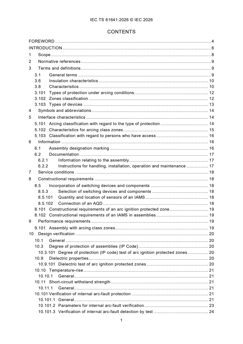
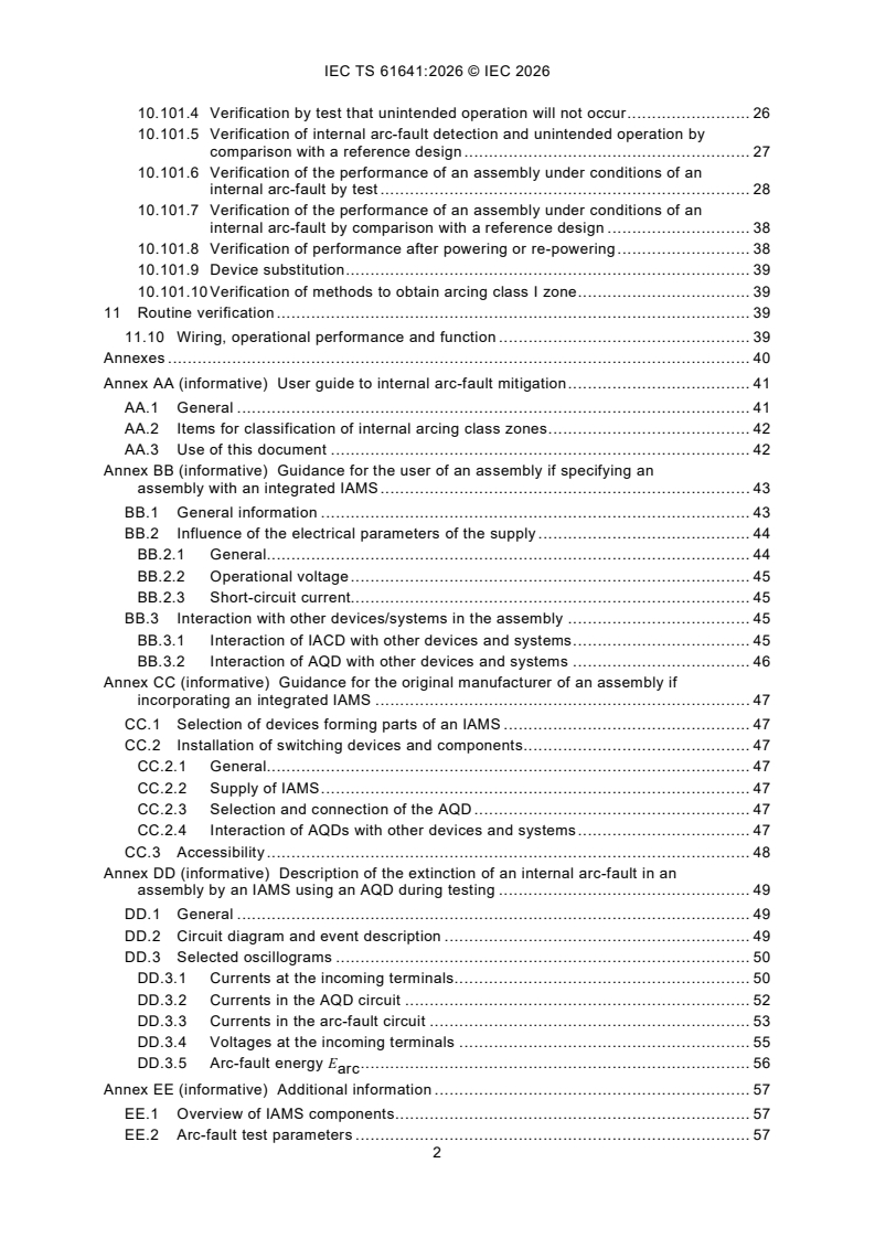
CONTENTS
FOREWORD . 4
INTRODUCTION . 6
1 Scope . 8
2 Normative references . 9
3 Terms and definitions . 9
3.1 General terms . 9
3.6 Insulation characteristics . 10
3.8 Characteristics . 10
3.101 Types of protection under arcing conditions . 12
3.102 Zones classification . 12
3.103 Types of devices . 13
4 Symbols and abbreviations . 14
5 Interface characteristics . 14
5.101 Arcing classification with regard to the type of protection . 14
5.102 Characteristics for arcing class zones . 15
5.103 Classification with regard to persons who have access . 16
6 Information . 16
6.1 Assembly designation marking . 16
6.2 Documentation . 17
6.2.1 Information relating to the assembly. 17
6.2.2 Instructions for handling, installation, operation and maintenance . 17
7 Service conditions . 18
8 Constructional requirements . 18
8.5 Incorporation of switching devices and components . 18
8.5.3 Selection of switching devices and components . 18
8.5.101 Quantity and location of sensors of an IAMS . 18
8.5.102 Connection of an AQD . 18
8.101 Constructional requirements of an arc ignition protected zone . 19
8.102 Constructional requirements of an IAMS in assemblies . 19
9 Performance requirements . 19
9.101 Assembly with arcing class zones. 19
10 Design verification . 20
10.1 General . 20
10.3 Degree of protection of assemblies (IP Code) . 20
10.3.101 Degree of protection (IP code) test of arc ignition protected zones . 20
10.9 Dielectric properties . 20
10.9.101 Dielectric test of arc ignition protected zones . 20
10.10 Temperature-rise . 21
10.10.1 General. 21
10.11 Short-circuit withstand strength . 21
10.11.1 General. 21
10.101 Verification of internal arc-fault protection . 21
10.101.1 General. 21
10.101.2 Parameters for internal arc-fault verification . 23
10.101.3 Verification of internal arc-fault detection by test . 24
10.101.4 Verification by test that unintended operation will not occur . 26
10.101.5 Verification of internal arc-fault detection and unintended operation by
comparison with a reference design . 27
10.101.6 Verification of the performance of an assembly under conditions of an
internal arc-fault by test . 28
10.101.7 Verification of the performance of an assembly under conditions of an
internal arc-fault by comparison with a reference design . 38
10.101.8 Verification of performance after powering or re-powering . 38
10.101.9 Device substitution . 39
10.101.10 Verification of methods to obtain arcing class I zone . 39
11 Routine verification . 39
11.10 Wiring, operational performance and function . 39
Annexes . 40
Annex AA (informative) User guide to internal arc-fault mitigation . 41
AA.1 General . 41
AA.2 Items for classification of internal arcing class zones . 42
AA.3 Use of this document . 42
Annex BB (informative) Guidance for the user of an assembly if specifying an
assembly with an integrated IAMS . 43
BB.1 General information . 43
BB.2 Influence of the electrical parameters of the supply . 44
BB.2.1 General. 44
BB.2.2 Operational voltage . 45
BB.2.3 Short-circuit current. 45
BB.3 Interaction with other devices/systems in the assembly . 45
BB.3.1 Interaction of IACD with other devices and systems . 45
BB.3.2 Interaction of AQD with other devices and systems . 46
Annex CC (informative) Guidance for the original manufacturer of an assembly if
incorporating an integrated IAMS . 47
CC.1 Selection of devices forming parts of an IAMS . 47
CC.2 Installation of switching devices and components . 47
CC.2.1 General. 47
CC.2.2 Supply of IAMS . 47
CC.2.3 Selection and connection of the AQD . 47
CC.2.4 Interaction of AQDs with other devices and systems . 47
CC.3 Accessibility . 48
Annex DD (informative) Description of the extinction of an internal arc-fault in an
assembly by an IAMS using an AQD during testing . 49
DD.1 General . 49
DD.2 Circuit diagram and event description . 49
DD.3 Selected oscillograms . 50
DD.3.1 Currents at the incoming terminals . 50
DD.3.2 Currents in the AQD circuit . 52
DD.3.3 Currents in the arc-fault circuit . 53
DD.3.4 Voltages at the incoming terminals . 55
DD.3.5 Arc-fault energy E . 56
arc
Annex EE (informative) Additional information . 57
EE.1 Overview of IAMS components . 57
EE.2 Arc-fault test parameters . 57
EE.2.1 General. 57
EE.2.2 Parameters for internal arc-fault test . 59
EE.2.3 Backward compatibility . 63
Annex FF (informative) Comparison of verification clauses in IEC TS 61641:2026, IEC
TS 63107:2020 and IEC TR 61641:2014 . 66
Annex GG (informative) List of notes concerning certain countries . 70
Bibliography . 71
Figure 101 – Mounting frame for indicators . 30
Figure 102 – Examples of installation positions of the indicators. 31
Figure BB.1 – Time/current characteristic curves NH-fuse-links
Size 000 – 3 gG AC 400 V based on IEC 60269-2 . 44
Figure DD.1 – AQD test circuit diagram . 49
Figure DD.2 – Incoming currents at the beginning of the sequence . 50
Figure DD.3 – Currents and voltages at the incoming terminals at the end of the
sequence . 51
Figure DD.4 – Currents in the AQD circuit . 52
Figure DD.5 – Currents in the arc-fault circuit . 53
Figure DD.6 – Currents in the arc-fault circuit, curves magnified. 54
Figure DD.7 – Voltages at the incoming terminals . 55
Figure DD.8 – Electrical energy caused by the arc-fault currents and the voltages at
the incoming terminals with t as the start point for calculation. 56
Figure EE.1 – Overview of IAMS components . 57
Figure EE.2 – Concept of a black box testing . 58
Figure EE.3 – Parameters of short-circuit test with a current limiting device linked to a
black box testing concept . 58
Figure EE.4 – Parameters for internal arc-fault test in case when current is not limited
and arc does not self-extinguish or arc duration not limited . 60
Figure EE.5 – Parameters for internal arc-fault test in case when current is not limited
but arc self-extinguishes . 61
Figure EE.6 – Parameters for internal arc-fault test in case when both current and arc
duration are limited . 62
Table 101 – Symbols and abbreviated terms . 14
Table 102 – Overview of arcing classification with regard to the protection level . 15
Table 103 – Overview of arcing class zones and assessment of the test . 20
Table 104 – Sizes of the copper ignition wire without current-limiting protective device . 32
Table 105 – Sizes of the copper ignition wire with current-limiting protective device . 33
Table EE.1 – Overview regarding currents, arc duration and device operation . 63
Table EE.2 – Parameters of TR 61641:2014 vs this document . 63
Table FF.1 – Verification clauses . 67
INTERNATIONAL ELECTROTECHNICAL COMMISSION
____________
Low-voltage switchgear and controlgear assemblies -
Internal arc-fault protection of low-voltage switchgear and
controlgear assemblies in accordance with the IEC 61439 series
FOREWORD
1) The International Electrotechnical Commission (IEC) is a worldwide organization for standardization comprising
all national electrotechnical committees (IEC National Committees). The object of IEC is to promote international
co-operation on all questions concerning standardization in the electrical and electronic fields. To this end and
in addition to other activities, IEC publishes International Standards, Technical Specifications, Technical Reports,
Publicly Available Specifications (PAS) and Guides (hereafter referred to as "IEC Publication(s)"). Their
preparation is entrusted to technical committees; any IEC National Committee interested in the subject dealt with
may participate in this preparatory work. International, governmental and non-governmental organizations liaising
with the IEC also participate in this preparation. IEC collaborates closely with the International Organization for
Standardization (ISO) in accordance with conditions determined by agreement between the two organizations.
2) The formal decisions or agreements of IEC on technical matters express, as nearly as possible, an international
consensus of opinion on the relevant subjects since each technical committee has representation from all
interested IEC National Committees.
3) IEC Publications have the form of recommendations for international use and are accepted by IEC National
Committees in that sense. While all reasonable efforts are made to ensure that the technical content of IEC
Publications is accurate, IEC cannot be held responsible for the way in which they are used or for any
misinterpretation by any end user.
4) In order to promote international uniformity, IEC National Committees undertake to apply IEC Publications
transparently to the maximum extent possible in their national and regional publications. Any divergence between
any IEC Publication and the corresponding national or regional publication shall be clearly indicated in the latter.
5) IEC itself does not provide any attestation of conformity. Independent certification bodies provide conformity
assessment services and, in some areas, access to IEC marks of conformity. IEC is not responsible for any
services carried out by independent certification bodies.
6) All users should ensure that they have the latest edition of this publication.
7) No liability shall attach to IEC or its directors, employees, servants or agents including individual experts and
members of its technical committees and IEC National Committees for any personal injury, property damage or
other damage of any nature whatsoever, whether direct or indirect, or for costs (including legal fees) and
expenses arising out of the publication, use of, or reliance upon, this IEC Publication or any other IEC
Publications.
8) Attention is drawn to the Normative references cited in this publication. Use of the referenced publications is
indispensable for the correct application of this publication.
9) IEC draws attention to the possibility that the implementation of this document may involve the use of (a)
patent(s). IEC takes no position concerning the evidence, validity or applicability of any claimed patent rights in
respect thereof. As of the date of publication of this document, IEC had not received notice of (a) patent(s), which
may be required to implement this document. However, implementers are cautioned that this may not represent
the latest information, which may be obtained from the patent database available at https://patents.iec.ch. IEC
shall not be held responsible for identifying any or all such patent rights.
IEC TS 61641 has been prepared by subcommittee SC 121B: Low-voltage switchgear and
controlgear assemblies, of IEC technical committee TC 121: Switchgear and controlgear and
their assemblies for low voltage. It is a Technical Specification.
This edition cancels and replaces IEC TR 61641:2014 and IEC TS 63107:2020. This edition
constitutes a technical revision.
This edition includes the following significant technical changes with respect to the previous
edition:
a) Introduction of the term "arcing class zone", using the term "arcing classes" from the
previous document IEC TR 61641:2014.
b) Structured using of the terms "zone" and "area". "Area" is used to describe the place of
installation and the accessibility of the assembly (macro-environment). "Zone" is used in
this document to describe a defined space within the assembly (micro-environment).
c) Assembly protection is classified into two levels.
The text of this Technical Specification is based on the following documents:
Draft Report on voting
121B/228/DTS 121B/232/RVDTS
Full information on the voting for its approval can be found in the report on voting indicated in
the above table.
The language used for the development of this Technical Specification is English.
This document was drafted in accordance with ISO/IEC Directives, Part 2, and developed in
accordance with ISO/IEC Directives, Part 1 and ISO/IEC Directives, IEC Supplement, available
at www.iec.ch/members_experts/refdocs. The main document types developed by IEC are
described in greater detail at www.iec.ch/publications.
This document is to be used in conjunction with the IEC 61439 series.
It supplements or modifies the corresponding clauses in the IEC 61439 series.
The following numbering system is used:
– subclauses, tables and figures that are numbered starting from 101 are additional to those
in the IEC 61439 series;
– unless notes are in a new subclause or involve notes in the IEC 61439 series, they are
numbered starting from 101, including those in a replaced clause or subclause;
– additional annexes are lettered AA, BB, etc.
The reader's attention is drawn to the fact that Annex GG lists all of the "in-some-country"
clauses on differing practices of a less permanent nature relating to the subject of this document.
The committee has decided that the contents of this document will remain unchanged until the
stability date indicated on the IEC website under webstore.iec.ch in the data related to the
specific document. At this date, the document will be
– reconfirmed,
– withdrawn, or
– revised.
INTRODUCTION
This document deals with the internal arc-fault protection of low-voltage switchgear and
controlgear assemblies.
The IEC 61439 series of documents identifies rules and requirements for the interface
characteristics, service conditions, construction, performance and verification of low-voltage
switchgear and controlgear assemblies, hereafter called an assembly. The main objective of
the IEC 61439 series of documents is to provide assemblies that operate safely under normal
operating conditions. An internal arc-fault is not considered as a normal operating condition.
Therefore, no characteristics, design and verification requirements are given dealing with an
internal arc-fault within an assembly.
Assemblies built, operated and maintained according to the IEC 61439 series cannot exclude
the risk of occurrence of an internal arc-fault. On the rare occasions that they do occur, internal
arc-faults result from circumstances including:
– foreign objects inadvertently left in the assembly during manufacture, installation or
maintenance operations, e.g. a tool;
– faults in construction materials and components;
– entry of small animals like mice, snakes, etc.;
– use of an inappropriate assembly for the application resulting in incorrect operation,
overheating, accelerated ageing of insulation;
– unforeseen operating conditions or lack of maintenance;
– human error, poor or faulty workmanship whether under energized or de-energized
conditions.
Avoiding all of the above and similar circumstances results in a remote possibility of an internal
arc-fault. Any of these circumstances creates a higher possibility of an internal arc-fault, which
should be considered in a risk assessment.
The ignition of an internal arc-fault within an assembly generates various phenomena, such as
extreme overheating resulting in high overpressure inside the assembly and emission of hot
materials, gases and flame which may endanger people in close proximity to the assembly
causing burns from the potential projection of these hot materials and/or gases from the
assembly as well as impacts from suddenly opening doors, and damage to the assembly.
Due to the risk of personal injury, damage and loss of power availability because of an arc-fault
there is a demand for internal arc-fault verified assemblies.
There are various methods of mitigating the effects of internal arc-faults. Assemblies often use
several methods for protection against the risk of injury, damage and loss of power availability
as a consequence of an arc-fault.
This document describes the verification of an assembly under conditions of arcing in air due
to an internal failure where the mechanical construction of the assembly provides arc-fault
resistance, commonly called "passive" arc-fault protection, and an assembly which is fitted with
an internal arc-fault mitigation system (IAMS), commonly called "active" arc-fault protection.
The aim of the integration of the IAMS into assemblies is to reduce the released energy in case
of an internal arc-fault by using the activation of an internal arc-fault reduction device (IARD) in
order to:
– improve the ability of assemblies to reduce the risk of injury to personnel;
– reduce the consequential damage to assemblies;
– improve the power availability from assemblies for further service after an internal arc-fault.
The above-mentioned improvements are related only to an assembly complying with certain
parts of the IEC 61439 series.
The ability of an assembly to pass tests according to this document is only one aspect when
assessing the potential risk due to an internal arc-fault within an assembly. Risk assessments
should be carried out considering for example, the skill of personnel having access to the
assembly, any protective measures required, the working procedures applied and the conditions
in the location where the assembly is installed.
General information about internal arc-fault considerations and possible protective measures
from the perspective of the user of an assembly is given in IEC TR 61439-0:2022, Clause D.2
and Annex AA and Annex BB of this document.
1 Scope
This document identifies methods used to verify the ability of the assembly:
– to limit the risk of injury to personnel during an internal arc-fault;
– to limit the damage to an acceptable level as a result of an internal arc-fault;
– to improve the power availability following an internal arc-fault.
This document takes into consideration:
– the effects of the internal overpressure acting on covers, doors, etc.;
– the thermal effects of the internal arc-fault or its roots on the enclosures and of ejected hot
gases and glowing particles.
– the correct function of the IAMS within the assembly;
– the prevention of unintended operation of the IAMS within the assembly, for example caused
by switching arcs;
– the functioning behaviour of the IAMS immediately after the assembly is energized.
This document describes different methods to assess the performance of an assembly or zones
of an assembly in respect of arcing in air due to an internal failure:
– with "passive" arc-fault protection (provided by mechanical construction, e.g. suitable door
locks, hinges, pressure relief devices, barriers);
NOTE 1 This approach corresponds to the method according to IEC TR 61641:2014.
– with "active" arc-fault protection (with the integration of IAMS);
NOTE 2 This approach corresponds to the method according to IEC TS 63107:2020.
– with the use of an arc ignition protected zone (to make the ignition of an arc-fault an
extremely remote possibility).
NOTE 3 This approach corresponds to the method according to IEC TR 61641:2014.
IAMS consist of internal arc-fault control devices (IACD), e.g. optical-based IACD's in
accordance with IEC 60947-9-2 and internal arc-fault reduction devices (IARD), e.g. arc
quenching devices (AQDs) in accordance with IEC 60947-9-1 and short-circuit protection
devices SCPD's in accordance with IEC 60947-2 (see Figure EE.1). IAMS can be provided by
a combined-type device according to IEC 60947-9-2.
IEC 60364-4-42:2024 (Clause 427) provides guidance on the need for internal arc-fault
protection.
This document does not supersede any individual product standard. Individual devices are
required to comply with their relevant standard.
This document does not apply to integration of arc fault detection devices (AFDD) according to
IEC 62606.
Informative Annex AA gives guidance for the user (see IEC 61439-1:2020, 3.11) on internal arc-
fault mitigation.
Informative Annex BB gives guidance for the user (see IEC 61439-1:2020, 3.11) of assemblies
with "active" arc-fault protection (with the integration of IAMS).
Informative Annex CC gives guidance for the original manufacturer of an assembly when
incorporating an integrated IAMS.
This document does not consider other effects which can constitute a risk, such as emission of
toxic gases, loud noises and/or intense light. Furthermore, this document does not consider
conditions during maintenance work and the personal protective equipment used.
2 Normative references
The following documents are referred to in the text in such a way that some or all of their content
constitutes requirements of this document. For dated references, only the edition cited applies.
For undated references, the latest edition of the referenced document (including any
amendments) applies.
IEC 60529, Degrees of protection provided by enclosures (IP Code)
IEC 60947-9-1:2019, Low-voltage switchgear and controlgear - Part 9-1: Active arc-fault
mitigation systems - Arc quenching devices
IEC 60947-9-2:2021, Low-voltage switchgear and controlgear - Active arc-fault mitigation
systems - Part 9-2: Optical-based internal arc-detection and mitigation devices
IEC 61439-1:2020, Low-voltage switchgear and controlgear assemblies - Part 1: General rules
IEC 61439 (all parts), Low-voltage switchgear and controlgear assemblies
3 Terms and definitions
For the purposes of this document, the terms and definitions given in IEC 61439 series of
document and the following apply.
ISO and IEC maintain terminology databases for use in standardization at the following
addresses:
– IEC Electropedia: available at https://www.electropedia.org/
– ISO Online browsing platform: available at https://www.iso.org/obp
3.1 General terms
Additional terms and definitions:
3.1.101
internal arc-fault
free burning fault current through air arising from a fault between live parts of different potential
and/or between live parts and other conductive parts within an enclosed assembly
3.1.102
arcing class
protection level to differentiate the various methods of protection provided against effects of
arc-faults
3.1.103
access (to an assembly)
ability of a person to be in close proximity to an assembly to operate devices such as switches
and circuit-breakers that have external operating handles, buttons, etc. where all doors, covers
are closed and secured as in normal service
3.1.104
restricted access
access to the location of the assembly limited to authorized personnel only
Note 1 to entry: Technical measures to restrict access are, for example, placing the assembly in dedicated
switchgear rooms, behind walls, fences or obstacles. Organizational measures are for example safety instructions
or marking of gangways at the appropriate distance.
3.1.105
unrestricted access
access to the location of the assembly by any person, including ordinary persons
3.6 Insulation characteristics
Additional term and definition:
3.6.101
solid insulation
suitable non-liquid, non-gaseous, non-conducting material used to insulate conductive parts of
the electrical circuits of an assembly that can only be removed by the use of a tool or destruction
3.8 Characteristics
Additional terms and definitions:
3.8.101
current characteristics
3.8.101.1
prospective short-circuit current under arcing conditions
I
cp arc
value of the I (see IEC 61439-1:2020, 3.8.7 prospective short-circuit current) for which the
cp
assembly is able to meet the requirements of this document
Note 1 to entry: Former terms of the current(s) and compatibility to this term are mentioned in EE.2.3.
3.8.101.2
internal arc-fault current
I
arc
average RMS value for AC or mean value for DC of the short-circuit current under arcing
conditions over the duration of burning t
b
Note 1 to entry: Former terms of the current(s) and compatibility to this term are mentioned in EE.2.3.
3.8.101.3
peak internal arc-fault current
I
pk arc
highest peak value of short-circuit current under arcing conditions
Note 1 to entry: Former terms of the current(s) and compatibility to this term are mentioned in EE.2.3.
3.8.102
time characteristics
3.8.102.1
prospective internal arc-fault duration
t
cp arc
duration the power supply is applied to the assembly under internal arc-fault conditions for a
given prospective short-circuit current under arcing conditions I
cp arc
Note 1 to entry: Former terms of the time(s) and compatibility to this term are mentioned in EE.2.3.
3.8.102.2
duration of burning
t
b
total burning time of the internal arc-fault during a single test (comprising in the case of arcs
that extinguish and re-strike, the sum of the individual burning durations) expressed for each
phase individually in the case of a multi-phase system
3.8.102.3
arc ignition time
t
moment in time at which the ignition wire has vaporized, considered as a reference for the
measurement of an IACD time response
Note 1 to entry: See for clarification t is shown in Figure DD.7.
[SOURCE: IEC 60947-9-2:2021, 3.20, modified – Addition of "at which the ignition wire has
vaporized" and addition of the Note to entry.]
3.8.102.4
arc-fault mitigation time in an assembly
t
mtA
interval of time between the ignition t of the internal arc-fault and the effective commutation of
currents into the AQD
Note 1 to entry: Arc-fault mitigation time in an assembly is as described in Figure DD.5 between points c) and g).
Note 2 to entry: For applications without AQD(s), the arc-fault extinction time t of IEC 60947-9-2 can be used as
ae
an alternative to t .
mtA
3.8.102.5
arc-fault extinction time
t
ae
interval of time between the ignition of the internal arc-fault t and the complete
extinction of the same
Note 1 to entry: Extinction time can be determined by measuring upstream line current and IACD current,
alternatively downstream line current.
[SOURCE: IEC 60947-9-2:2021, 3.6. modified – Addition of t internal arc-fault, deletion of Note
2 to entry.]
3.8.103
other characteristics
3.8.103.1
arc-fault energy
E
arc
energy released by the arc during the internal arc-fault
Note 1 to entry: In this document, the arc-fault energy is the value determined by the measured voltages at the
incoming terminals of the assembly, the measured currents and durations. The formulas can be found in 10.101.6.6.1
and 10.101.6.6.2.
Additional terms and definitions:
3.101 Types of protection under arcing conditions
3.101.1
personnel protection under arcing conditions
ability to limit personal injury caused by the mechanical and thermal effects of an internal arc-
fault, other effects which can constitute a risk such as toxic gases or other risks as radiated
light flashes and noise not being considered
3.101.2
assembly protection under arcing conditions
ability of an assembly to limit the effects of an internal arc-fault inside the assembly to a zone
as defined by the manufacturer
3.101.3
assembly protection under arcing conditions with limited operation
ability to limit the effects of an internal arc-fault inside the assembly as defined by the
manufacturer and to allow conditional limited continued operation after such a fault
3.101.4
enhanced protection under arcing conditions
assembly protection considering faster power availability from the assembly by reducing
recommissioning time and improving personnel protection with further reduction of the risk of
personal injury caused by the mechanical and thermal effects of an internal arc-fault due to the
reduction of internal arc-fault energy
3.102 Zones classification
3.102.1
arcing class zone
space within an assembly defined by the original manufacturer that fulfils the requirements of
a given protection level against effects of internal arc-faults
Note 1 to entry: An arcing class zone can be defined for the complete assembly or part of the assembly (see
Table 102).
3.102.1.1
IAMS protected zone
arcing class zone monitored by an IAMS where an internal arc-fault is detected and then
mitigated and finally extinguished
3.102.1.2
arc ignition protected zone
arcing class zone where specific measures are provided to ensure the initiation of an arc-fault
is an extremely remote possibility
Note 1 to entry: The concept of an arc ignition protected zone takes into account that insulation is an important
means to reduce the probability of an internal arc-fault ignition and the possibility of an internal arc-fault propagating
within the assembly. When adopting the concept of arc ignition protected zones, it should be recognized that also
within an arc ignition protected zone there is a residual risk of an internal arc-fault ignition, either due to damage of
the insulation itself or due to failure of the insulated conductor or its connections. The quality and reliability of the
conductor, its connections and its insulation within an arc ignition protected zone and effectiveness of maintenance
of the assembly are crucial for the additional internal arc-fault protection offered by the arc ignition protected zone.
Note 2 to entry: See 8.101 for constructional requirements of an arc ignition protected zone.
Note 3 to entry: Arcing class I zone(s) is an alternative way to achieve risk reduction related to the protection of
personnel and the assembly by reducing the probability of an internal arc-fault.
3.103 Types of devices
3.103.1
internal arc-fault mitigation system
IAMS
system consisting of an internal arc-fault control device (IACD) and an internal arc-fault
reduction device (IARD) that operates in the case of an internal arc-fault
Note 1 to entry: An IAMS can include a "combined-type" single device which combines the functions of an IACD
and an IARD as defined in IEC 60947-9-2.
3.103.2
internal arc-fault control device
IACD
device intended to detect an internal arc-fault, which provides a signal for operation of a
separate IARD, or automatically mitigates the internal arc-fault
Note 1 to entry: An IACD with mitigation capability combines in the same device internal arc-fault detection and
breaking or making capabilities.
[SOURCE: IEC 60947-9-2:2021, 3.3, modified – Substitution of "mitigation device" with "IARD"
and deletion of Note 2 to entry.]
3.103.3
internal arc-fault reduction device
IARD
device intended to reduce the energy released by an internal arc-fault, which receives a signal
for operation from an IACD
Note 1 to entry: An IARD can be achieved by a SCPD, AQD with its associated SCPD(s), or an IALD (internal arc-
fault limiting device) with its associated SCPD(s).
3.103.4
internal arc-fault limiting device
IALD
IARD intended to reduce the arc-fault current below a particular level other than a SCPD with
current limiting functionality e.g. fuse or circuit-breaker
Note 1 to entry: See Figure EE.1.
3.103.5
arc quenching device
AQD
IARD intended to eliminate internal arc-faults by creating a lower impedance current path in
order to cause the arcing current to transfer to the new current path
[SOURCE: IEC 60947-9-1:2019, 3.1, modified – In the definition, replacement of "device" with
"IARD" and deletion of Note 1 to entry.]
3.103.6
automatic transfer switching equipment
ATSE
self-acting transfer switching equipment
Note 1 to entry: An ATSE normally includes all necessary devices for monitoring and transferring operations.
Note 2 to entry: An ATSE can have an optional feature for manual operation.
[SOURCE: IEC 60947-6-1:2021, 3.3.4, modified – In the definition, deletion of "including all
necessary sensing inputs, monitoring, and control logic for transferring operations", addition of
a Note to entry, modification of the text of the existing Note to entry.]
3.103.7
optical sensor
sensor used to detect the optical emission of an internal arc-fault
[SOURCE: IEC 60947-9-2:2021, 3.11]
4 Symbols and abbreviations
For the purposes of this document, symbols and abbreviated terms given in the
IEC 61439 series of documents, as well as those given in Table 101, apply.
Table 101 – Symbols and abbreviated terms
Symbol/Abbreviation Term Term number
SCPD short-circuit protective device IEC 61439-1:2020 3.1.11
I prospective short-circuit current under arcing 3.8.101.1
cp arc
conditions
I internal arc-fault current 3.8.101.2
arc
I peak internal arc-fault current 3.8.101.3
pk arc
t prospective internal arc-fault duration 3.8.102.1
cp arc
t duration of burning 3.8.102.2
b
t arc ignition time 3.8.102.3
t arc-fault mitigation time in an assembly 3.8.102.4
mtA
t arc-fault extinction time 3.8.102.5
ae
E arc-fault energy 3.8.103.1
arc
IAMS internal arc-fault mitigation system 3.103.1
IACD internal arc-fault control device 3.103.2
IARD internal arc-fault reduction device 3.103.3
IALD internal arc-fault limiting device 3.103.4
AQD arc quenching device 3.103.5
ATSE automatic transfer switching equipment 3.103.6
5 Interface characteristics
Clause 5 of the IEC 61439 series of documents is applicable except as follows.
Additional subclau
...