

ISO 19859:2016
(Main)Gas turbine applications — Requirements for power generation
General Information
- Abstract
ISO 19859:2016 specifies the minimum technical and documentation requirements for the evaluation and procurement of gas turbine systems for electrical power generation. It applies to simple cycle and combined cycle gas turbines for both onshore and offshore applications, where applicable. It also applies to gas turbines used in cogeneration (see ISO 11086:1996, Annex B). Testing of the gas turbine in combination with a generator is included in the scope. It is not applicable to gas turbines used for all types of propulsion including aircraft, mobile barges, floating production vessels and marine propulsion applications and microturbines. ISO 19859:2016 defines the requirements for gas turbine power generation from an international perspective based on the content of existing, recognized ISO and IEC standards to the greatest extent practical. Nonetheless, it is recognized that within the industry other codes or standards are used, some of which are included in the text of this International Standard. The use of other such codes and standards is permissible provided an appropriate and acceptable level of requirements, functional design and safety is achieved and agreement has been reached for their use between the Purchaser and Contractor and such use is suitably documented. Consideration should be given to applying/using standards in the following hierarchical order: international; regional; national; local. ISO 19859:2016 identifies the requirements for both the Purchaser and Contractor attributable to the design and procurement of a gas turbine power generation package. The defined requirements apply to the scope of supply, except where excluded, encompassing the following equipment and the associated selected options, located within the power generation package, (see 3.14), listed below: - gas turbine package; - load shaft coupling and clutch, as applicable; - air inlet system; - exhaust system; - fuel equipment; - control equipment; - electrical equipment; - additional auxiliary systems, including starting, lubrication, barring, compressor wash, pipework, drains and vents; - fire and gas protection; - cooling water equipment. Where applicable to the integrity of the gas turbine package, the interface and applicable design requirements are included for equipment, utilities and supplies that interface with the power generation package. The following equipment is excluded from the scope of supply, but references are included where required for interface or performance measurement: - generator and auxiliary systems, except the module control option; - steam turbine and auxiliary systems; - equipment external to the power generation package. Data sheets in Annex A of this International Standard are provided for defining requirements and exchanging information between the Purchaser and the Contractor. The Purchaser fills in the data sheets for the tender and forwards them to the Contractor. The Contractor responds by completing the applicable data sheets for their tender. Annex A identifies the different types of data sheets and how they are to be used. Where the Contractor does not comply with a selected requirement of this International Standard, this is detailed as an exception, referencing the applicable clause and describing the deviation and any alternatives available in a document listing all the exceptions taken. Where the text in this International Standard requests procedures and operating, maintenance and commissioning manual information or equipment that would require the disclosure/supply of proprietary information/equipment which the Contractor is not prepared to release, such exceptions are listed. Where this situation exists, the Contractor will be prepared to release appropriate personnel and equipment to undertake all the tasks that otherwise would be undertaken by the Purchaser. A bullet ● at the beginning of a paragraph in the text of this International Standard indicates an optiona
- Status
- Published
- Publication Date
- 09-Jun-2016
- Technical Committee
- ISO/TC 192 - Gas turbines
- Drafting Committee
- ISO/TC 192 - Gas turbines
- Current Stage
- 9020 - International Standard under periodical review
- Start Date
- 15-Jul-2026
- Completion Date
- 15-Jul-2026
Buy Documents


ISO 19859:2016 - Gas turbine applications — Requirements for power generation Released:6/10/2016
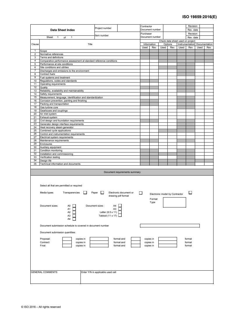


ISO19859_2016_1.Data_Sheet_Index - ISO 19859:2016 - Gas turbine applications — Requirements for power generation/10/2016
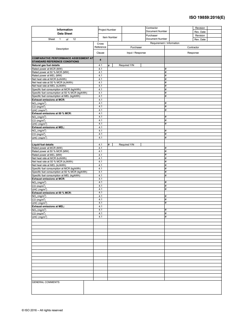
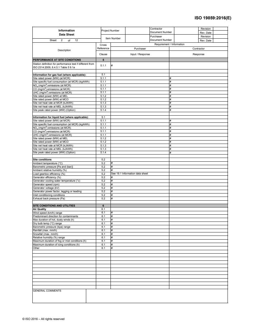
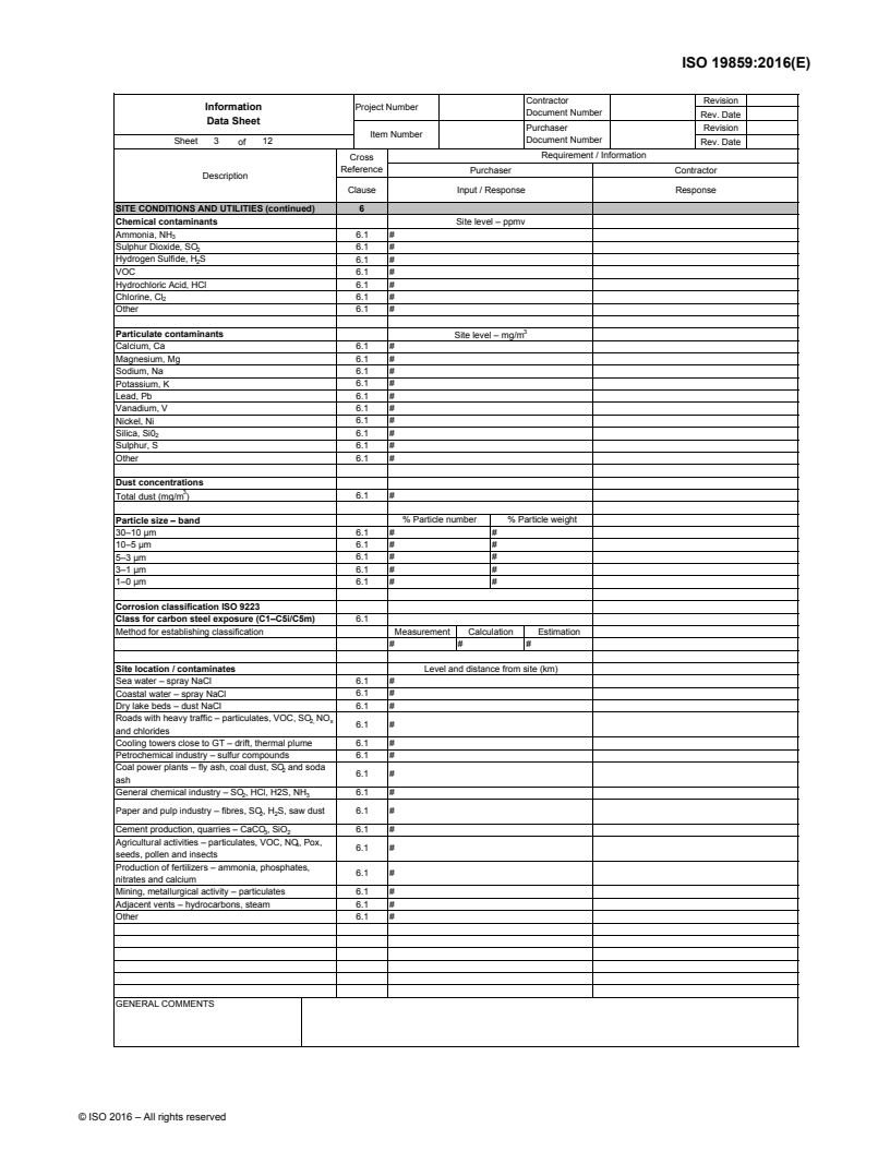
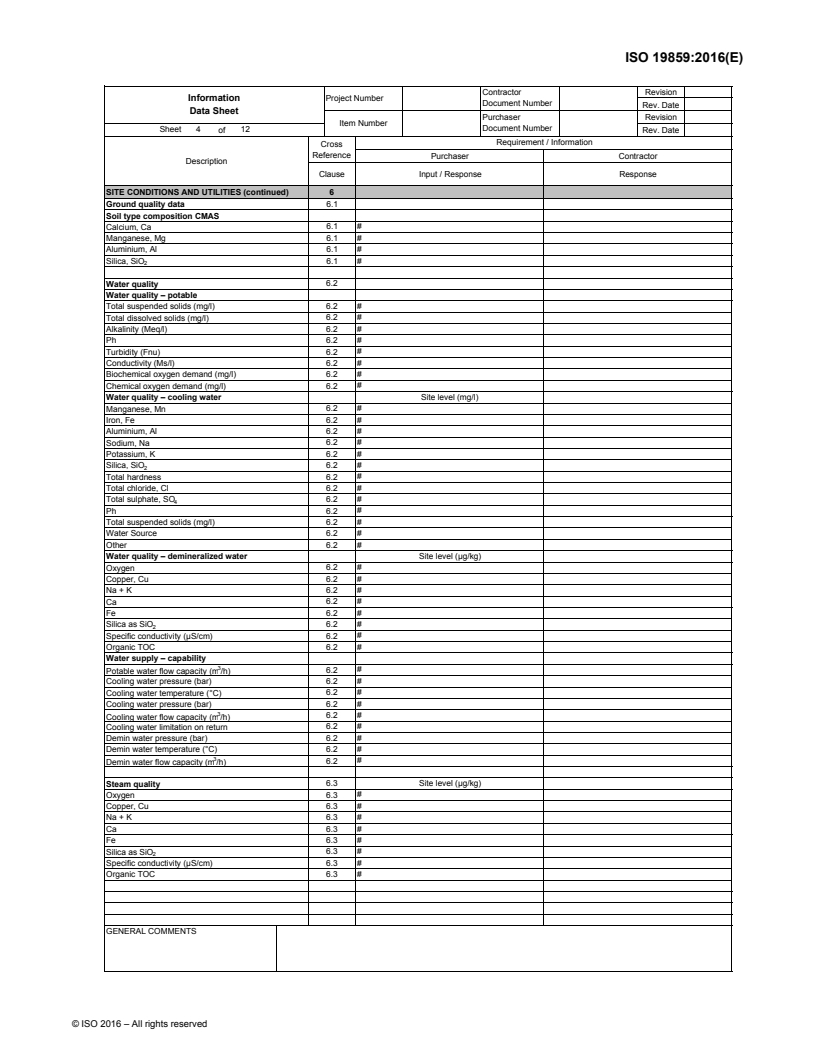
ISO19859_2016_2.Information_Data_Sheet - ISO 19859:2016 - Gas turbine applications — Requirements for power generation/10/2016
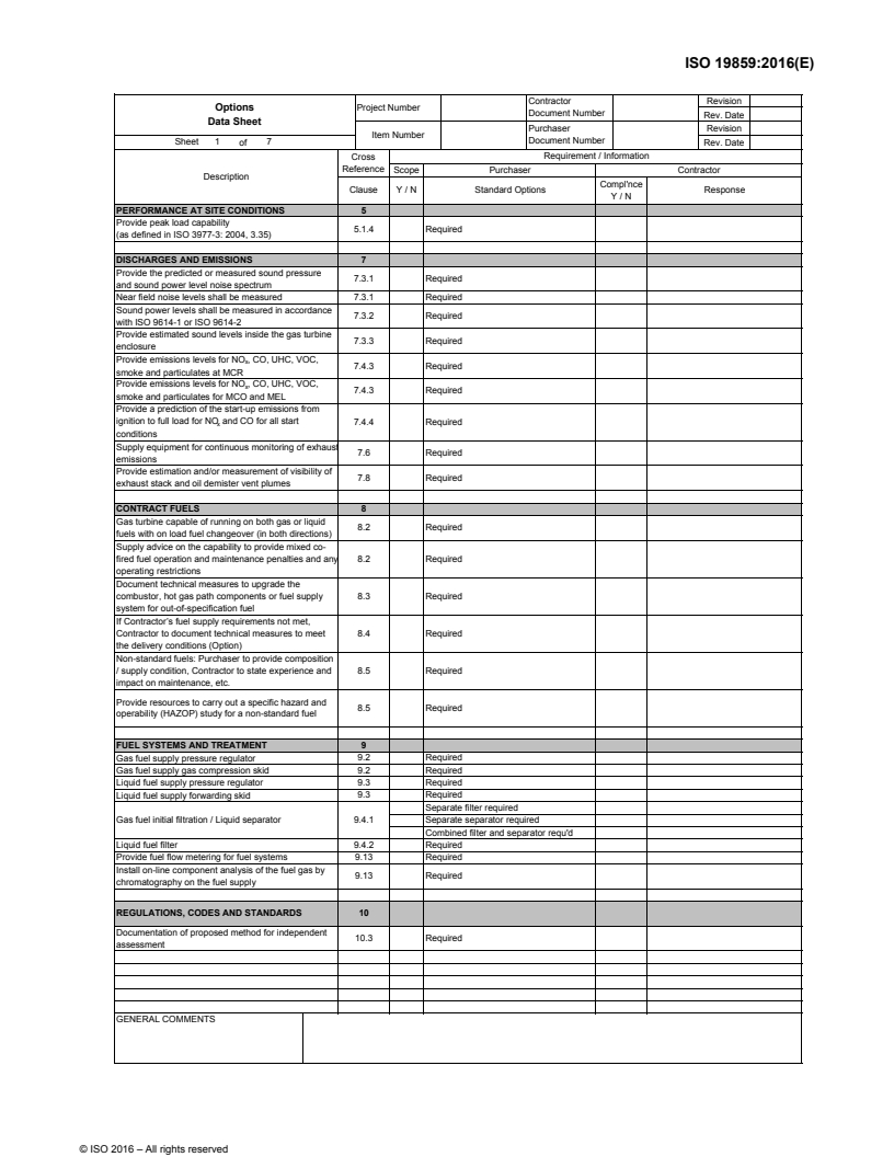
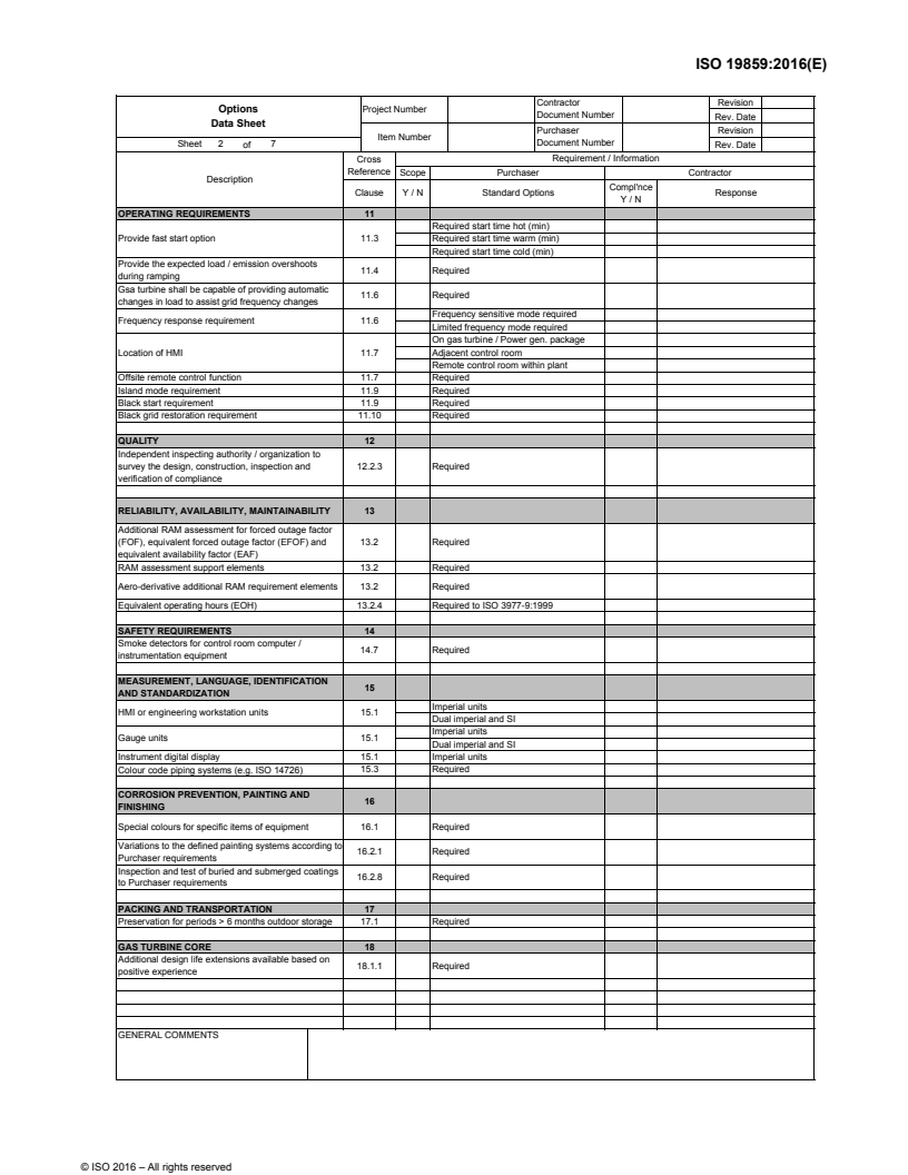
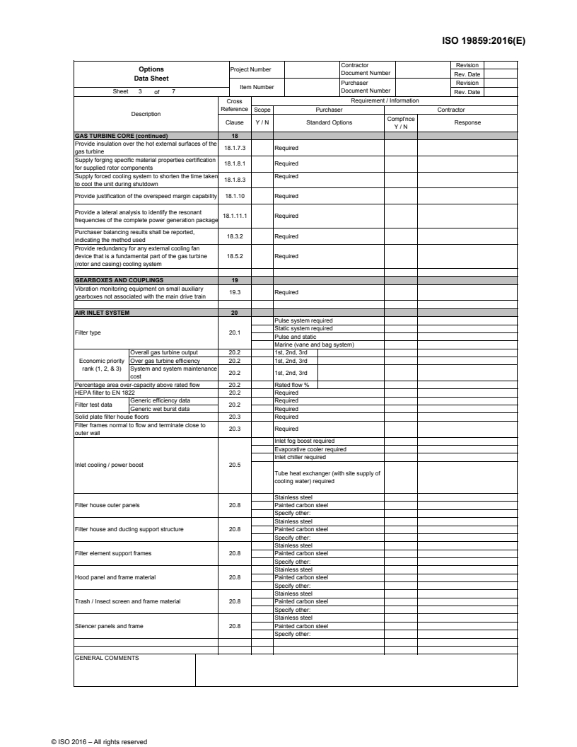
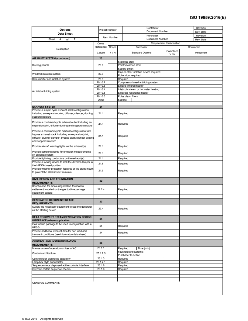
ISO19859_2016_3.Options_Data_Sheet - ISO 19859:2016 - Gas turbine applications — Requirements for power generation/10/2016
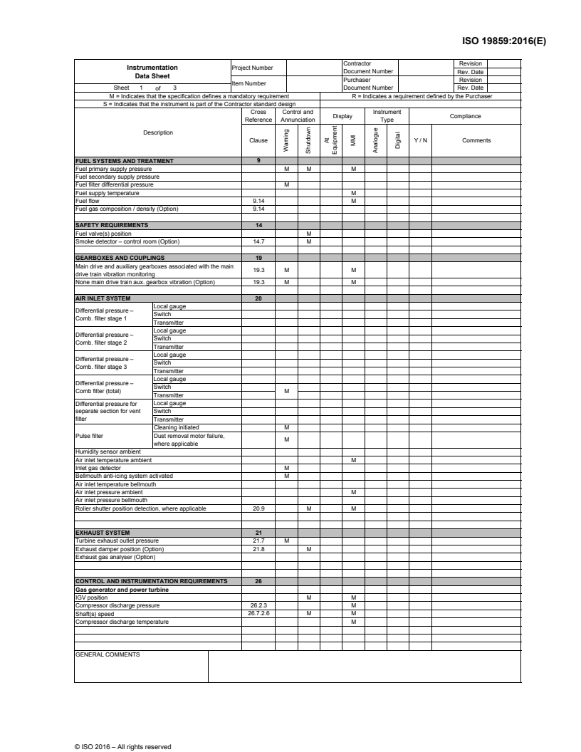
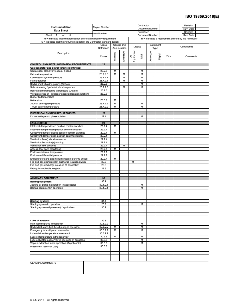
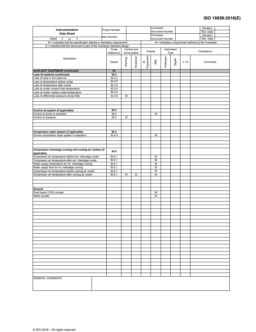

ISO19859_2016_4.Instrumentation_Data_Sheet - ISO 19859:2016 - Gas turbine applications — Requirements for power generation/10/2016
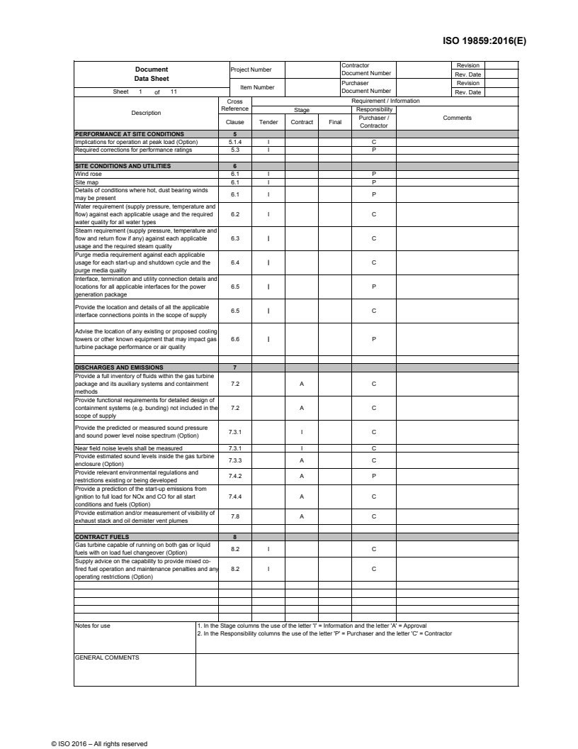
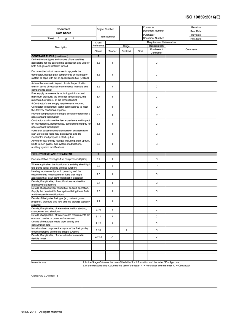
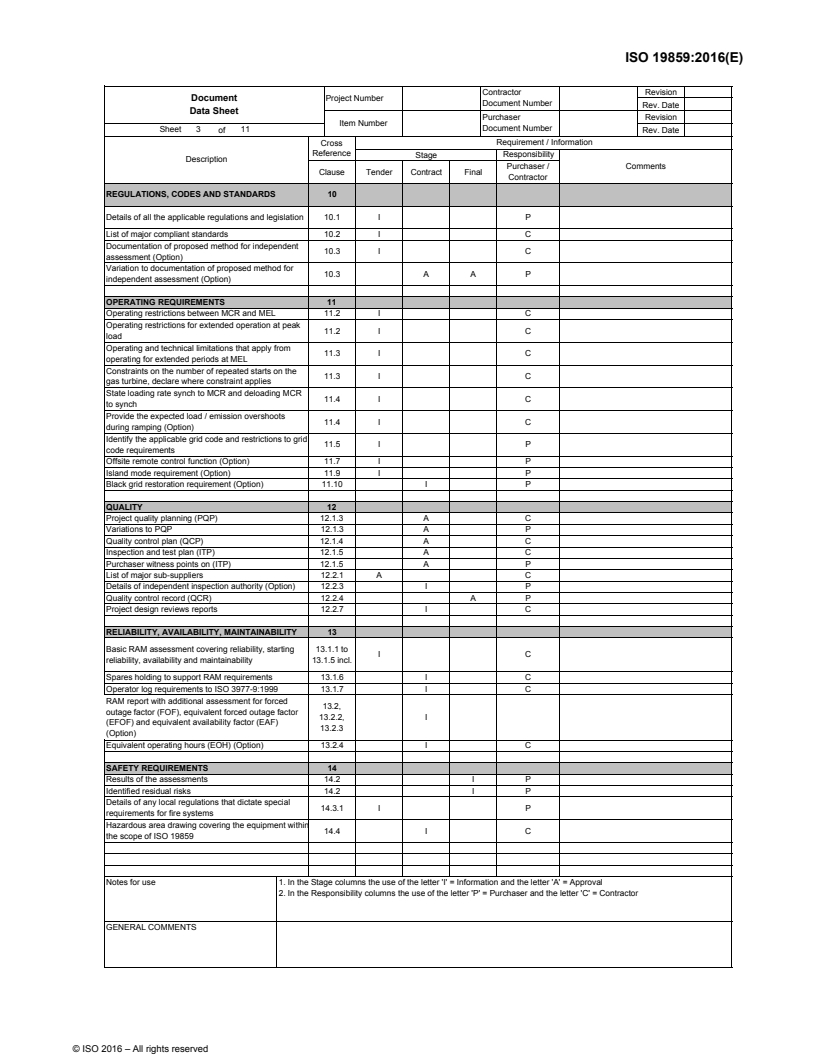
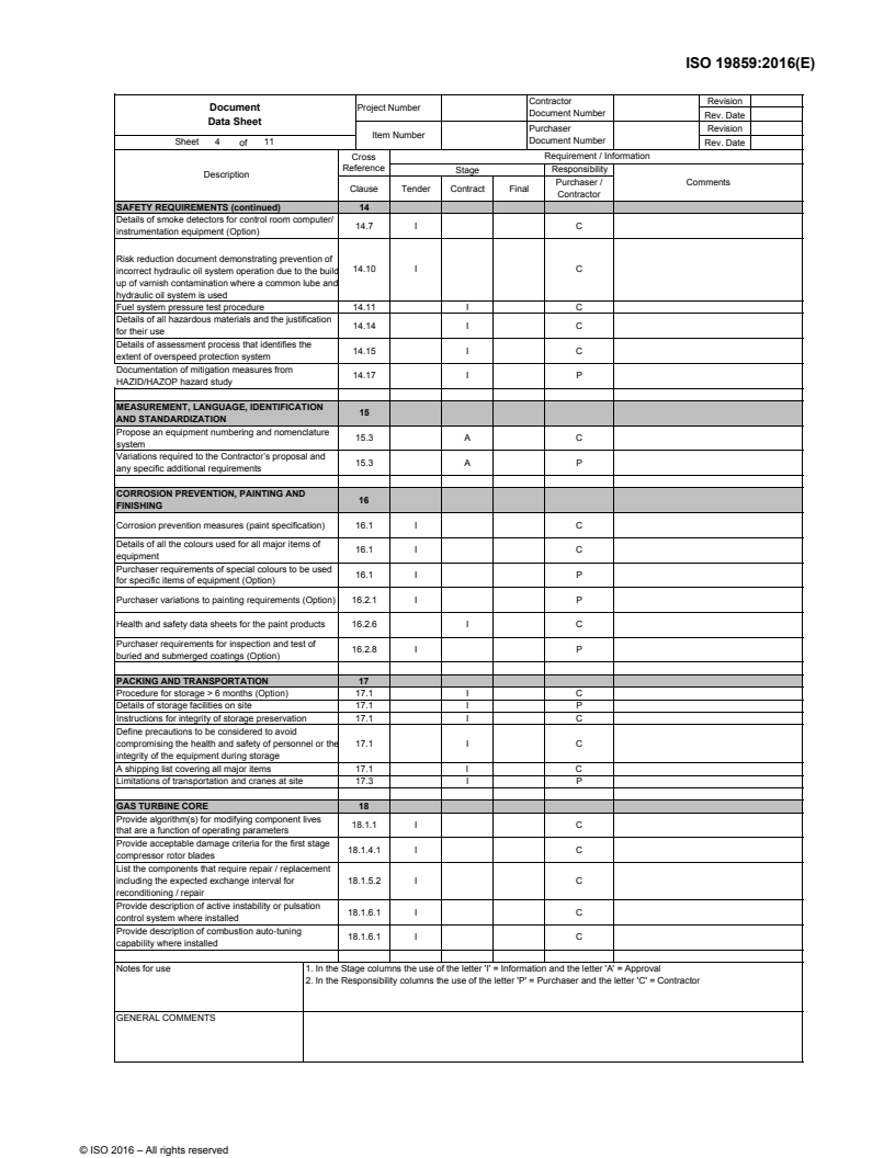
ISO19859_2016_5.Document_Data_Sheet - ISO 19859:2016 - Gas turbine applications — Requirements for power generation/10/2016
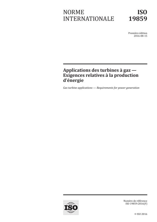

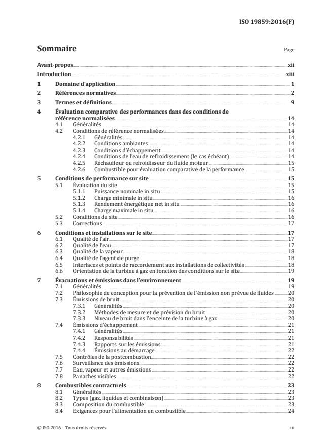
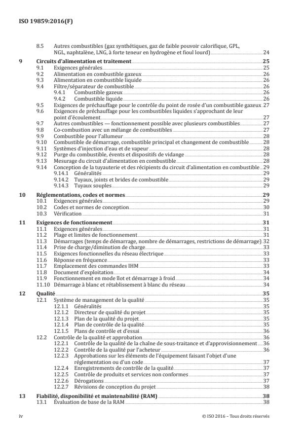
ISO 19859:2016 - Applications des turbines a gaz — Exigences relatives a la production d'énergie Released:8/5/2016
Overview
ISO 19859:2016 - Gas turbine applications - Requirements for power generation is an international standard that defines the minimum technical and documentation requirements for evaluating and procuring gas turbine systems used for electrical power generation. It covers both simple cycle and combined cycle gas turbines for onshore and offshore installations and includes testing of the gas turbine in combination with a generator. The standard is intended to harmonize purchaser and contractor responsibilities and to reference recognized ISO/IEC and other industry codes where practical.
Key topics and technical requirements
ISO 19859:2016 addresses the full lifecycle and interface requirements for a gas turbine power generation package. Major technical areas include:
Scope of supply and interfaces
- Defines equipment within the power generation package (gas turbine package, air inlet, exhaust, fuel, controls, electrical and auxiliary systems, fire/gas protection, cooling water).
- Identifies excluded items (generator and its auxiliaries except module control option, steam turbines, external equipment) and interface responsibilities.
Performance and testing
- Comparative performance assessment at standard reference conditions and site conditions, including site rating, net heat rate, minimum load and peak load.
- Testing requirements when the turbine is combined with a generator.
Site conditions and utilities
- Requirements for ambient air, water and steam quality, purge media, interface and orientation due to site constraints.
Emissions and environmental
- Design philosophy and requirements for preventing unplanned fluid release, exhaust emissions, noise measurement, visible plumes, and emission monitoring.
Fuel and fuel systems
- Contract fuel definitions, fuel composition, alternative fuels (syngas, LNG, high hydrogen fuels), fuel supply and treatment, metering, purge and filtration.
Operation, quality and reliability
- Operating limits, start/stop cycles, grid requirements (frequency response, island/black start), project quality management, reliability/maintainability and documentation.
Procurement documentation
- Annex A data sheets for tendering: purchasers complete and forward to contractors; contractors respond with compliance or documented exceptions.
Practical applications - who uses this standard
ISO 19859 is used by:
- Utilities, independent power producers (IPPs) and plant owners specifying gas turbine purchases
- OEMs, EPC contractors and system integrators preparing proposals and designs
- Procurement teams and contract managers for tendering and supplier evaluation
- Commissioning, operations and maintenance teams for acceptance testing, documentation and performance verification
- Regulators and consultants assessing compliance with international design and environmental requirements
Related standards
- ISO 11086:1996 (cogeneration) - referenced for cogeneration applications
- Existing ISO and IEC standards and recognized national/regional codes - ISO 19859 is intended to align with these where practical; users should apply standards in hierarchical order: international → regional → national → local.
Keywords: ISO 19859, ISO 19859:2016, gas turbine power generation, procurement, performance assessment, fuel systems, emissions, combined cycle, simple cycle, onshore, offshore, cogeneration.
Buy Documents
ISO 19859:2016 - Gas turbine applications — Requirements for power generation Released:6/10/2016
ISO19859_2016_1.Data_Sheet_Index - ISO 19859:2016 - Gas turbine applications — Requirements for power generation/10/2016
ISO19859_2016_2.Information_Data_Sheet - ISO 19859:2016 - Gas turbine applications — Requirements for power generation/10/2016
ISO19859_2016_3.Options_Data_Sheet - ISO 19859:2016 - Gas turbine applications — Requirements for power generation/10/2016
ISO19859_2016_4.Instrumentation_Data_Sheet - ISO 19859:2016 - Gas turbine applications — Requirements for power generation/10/2016
ISO19859_2016_5.Document_Data_Sheet - ISO 19859:2016 - Gas turbine applications — Requirements for power generation/10/2016
ISO 19859:2016 - Applications des turbines a gaz — Exigences relatives a la production d'énergie Released:8/5/2016
Get Certified
Connect with accredited certification bodies for this standard

DNV
DNV is an independent assurance and risk management provider.

Lloyd's Register
Lloyd's Register is a global professional services organisation specialising in engineering and technology.
DNV Energy Systems
Energy and renewable energy certification.
Sponsored listings
Frequently Asked Questions
ISO 19859:2016 is a standard published by the International Organization for Standardization (ISO). Its full title is "Gas turbine applications — Requirements for power generation". This standard covers: ISO 19859:2016 specifies the minimum technical and documentation requirements for the evaluation and procurement of gas turbine systems for electrical power generation. It applies to simple cycle and combined cycle gas turbines for both onshore and offshore applications, where applicable. It also applies to gas turbines used in cogeneration (see ISO 11086:1996, Annex B). Testing of the gas turbine in combination with a generator is included in the scope. It is not applicable to gas turbines used for all types of propulsion including aircraft, mobile barges, floating production vessels and marine propulsion applications and microturbines. ISO 19859:2016 defines the requirements for gas turbine power generation from an international perspective based on the content of existing, recognized ISO and IEC standards to the greatest extent practical. Nonetheless, it is recognized that within the industry other codes or standards are used, some of which are included in the text of this International Standard. The use of other such codes and standards is permissible provided an appropriate and acceptable level of requirements, functional design and safety is achieved and agreement has been reached for their use between the Purchaser and Contractor and such use is suitably documented. Consideration should be given to applying/using standards in the following hierarchical order: international; regional; national; local. ISO 19859:2016 identifies the requirements for both the Purchaser and Contractor attributable to the design and procurement of a gas turbine power generation package. The defined requirements apply to the scope of supply, except where excluded, encompassing the following equipment and the associated selected options, located within the power generation package, (see 3.14), listed below: - gas turbine package; - load shaft coupling and clutch, as applicable; - air inlet system; - exhaust system; - fuel equipment; - control equipment; - electrical equipment; - additional auxiliary systems, including starting, lubrication, barring, compressor wash, pipework, drains and vents; - fire and gas protection; - cooling water equipment. Where applicable to the integrity of the gas turbine package, the interface and applicable design requirements are included for equipment, utilities and supplies that interface with the power generation package. The following equipment is excluded from the scope of supply, but references are included where required for interface or performance measurement: - generator and auxiliary systems, except the module control option; - steam turbine and auxiliary systems; - equipment external to the power generation package. Data sheets in Annex A of this International Standard are provided for defining requirements and exchanging information between the Purchaser and the Contractor. The Purchaser fills in the data sheets for the tender and forwards them to the Contractor. The Contractor responds by completing the applicable data sheets for their tender. Annex A identifies the different types of data sheets and how they are to be used. Where the Contractor does not comply with a selected requirement of this International Standard, this is detailed as an exception, referencing the applicable clause and describing the deviation and any alternatives available in a document listing all the exceptions taken. Where the text in this International Standard requests procedures and operating, maintenance and commissioning manual information or equipment that would require the disclosure/supply of proprietary information/equipment which the Contractor is not prepared to release, such exceptions are listed. Where this situation exists, the Contractor will be prepared to release appropriate personnel and equipment to undertake all the tasks that otherwise would be undertaken by the Purchaser. A bullet ● at the beginning of a paragraph in the text of this International Standard indicates an optiona
ISO 19859:2016 specifies the minimum technical and documentation requirements for the evaluation and procurement of gas turbine systems for electrical power generation. It applies to simple cycle and combined cycle gas turbines for both onshore and offshore applications, where applicable. It also applies to gas turbines used in cogeneration (see ISO 11086:1996, Annex B). Testing of the gas turbine in combination with a generator is included in the scope. It is not applicable to gas turbines used for all types of propulsion including aircraft, mobile barges, floating production vessels and marine propulsion applications and microturbines. ISO 19859:2016 defines the requirements for gas turbine power generation from an international perspective based on the content of existing, recognized ISO and IEC standards to the greatest extent practical. Nonetheless, it is recognized that within the industry other codes or standards are used, some of which are included in the text of this International Standard. The use of other such codes and standards is permissible provided an appropriate and acceptable level of requirements, functional design and safety is achieved and agreement has been reached for their use between the Purchaser and Contractor and such use is suitably documented. Consideration should be given to applying/using standards in the following hierarchical order: international; regional; national; local. ISO 19859:2016 identifies the requirements for both the Purchaser and Contractor attributable to the design and procurement of a gas turbine power generation package. The defined requirements apply to the scope of supply, except where excluded, encompassing the following equipment and the associated selected options, located within the power generation package, (see 3.14), listed below: - gas turbine package; - load shaft coupling and clutch, as applicable; - air inlet system; - exhaust system; - fuel equipment; - control equipment; - electrical equipment; - additional auxiliary systems, including starting, lubrication, barring, compressor wash, pipework, drains and vents; - fire and gas protection; - cooling water equipment. Where applicable to the integrity of the gas turbine package, the interface and applicable design requirements are included for equipment, utilities and supplies that interface with the power generation package. The following equipment is excluded from the scope of supply, but references are included where required for interface or performance measurement: - generator and auxiliary systems, except the module control option; - steam turbine and auxiliary systems; - equipment external to the power generation package. Data sheets in Annex A of this International Standard are provided for defining requirements and exchanging information between the Purchaser and the Contractor. The Purchaser fills in the data sheets for the tender and forwards them to the Contractor. The Contractor responds by completing the applicable data sheets for their tender. Annex A identifies the different types of data sheets and how they are to be used. Where the Contractor does not comply with a selected requirement of this International Standard, this is detailed as an exception, referencing the applicable clause and describing the deviation and any alternatives available in a document listing all the exceptions taken. Where the text in this International Standard requests procedures and operating, maintenance and commissioning manual information or equipment that would require the disclosure/supply of proprietary information/equipment which the Contractor is not prepared to release, such exceptions are listed. Where this situation exists, the Contractor will be prepared to release appropriate personnel and equipment to undertake all the tasks that otherwise would be undertaken by the Purchaser. A bullet ● at the beginning of a paragraph in the text of this International Standard indicates an optiona
ISO 19859:2016 is classified under the following ICS (International Classification for Standards) categories: 27.040 - Gas and steam turbines. Steam engines; 29.160.99 - Other standards related to rotating machinery. The ICS classification helps identify the subject area and facilitates finding related standards.
ISO 19859:2016 is available in PDF format for immediate download after purchase. The document can be added to your cart and obtained through the secure checkout process. Digital delivery ensures instant access to the complete standard document.
Standards Content (Sample)
INTERNATIONAL ISO
STANDARD 19859
First edition
2016-06-15
Gas turbine applications —
Requirements for power generation
Applications des turbines à gaz — Exigences relatives à la production
d’energie
Reference number
©
ISO 2016
© ISO 2016, Published in Switzerland
All rights reserved. Unless otherwise specified, no part of this publication may be reproduced or utilized otherwise in any form
or by any means, electronic or mechanical, including photocopying, or posting on the internet or an intranet, without prior
written permission. Permission can be requested from either ISO at the address below or ISO’s member body in the country of
the requester.
ISO copyright office
Ch. de Blandonnet 8 • CP 401
CH-1214 Vernier, Geneva, Switzerland
Tel. +41 22 749 01 11
Fax +41 22 749 09 47
copyright@iso.org
www.iso.org
ii © ISO 2016 – All rights reserved
Contents Page
Foreword .xii
Introduction .xiii
1 Scope . 1
2 Normative references . 2
3 Terms and definitions . 8
4 Comparative performance assessment at standard reference conditions .12
4.1 General .12
4.2 Standard reference conditions .13
4.2.1 General.13
4.2.2 Ambient conditions .13
4.2.3 Exhaust conditions .13
4.2.4 Cooling water conditions (if applicable) .13
4.2.5 Working fluid heater or cooler .13
4.2.6 Fuel for comparative performance assessment .13
5 Performance at site conditions .14
5.1 Site rating .14
5.1.1 Site rated power .14
5.1.2 Site minimum load .14
5.1.3 Site net heat rate .14
5.1.4 Site peak load .14
5.2 Site conditions .14
5.3 Corrections .15
6 Site conditions and utilities .15
6.1 Air quality .15
6.2 Water quality .16
6.3 Steam quality .16
6.4 Purge media quality .16
6.5 Interface and utility connection points .17
6.6 Gas turbine orientation due to site conditions .17
7 Discharges and emissions to the environment .18
7.1 General .18
7.2 Design philosophy for prevention of unplanned release of fluids .18
7.3 Noise emissions .18
7.3.1 General.18
7.3.2 Methods for sound measurements and predictions .18
7.3.3 Sound level within the gas turbine enclosure .19
7.4 Exhaust emissions .19
7.4.1 General.19
7.4.2 Responsibilities .19
7.4.3 Reporting emissions .19
7.4.4 Start-up emissions . .20
7.5 Post-combustion controls.20
7.6 Emission monitoring .20
7.7 Water, steam and other emissions .20
7.8 Visible plumes .20
8 Contract fuels .21
8.1 General .21
8.2 Types (gas, liquids and combination) .21
8.3 Fuel composition .21
8.4 Fuel supply requirements .22
8.5 Alternative fuels (syngas, low calorific value gas, LPG, NGL, Naphtha, LNG, high
hydrogen and residual fuel oil) .22
9 Fuel systems and treatment .23
9.1 General requirements .23
9.2 Gas fuel supply .23
9.3 Liquid fuel supply .23
9.4 Fuel filter/separator . .24
9.4.1 Gas fuel .24
9.4.2 Liquid fuel .24
9.5 Pre-heating requirements for the dew point control of fuel gas.24
9.6 Pre-heating requirements for liquid fuels approaching their pour point .24
9.7 Alternative fuels – multi-fuel capability .24
9.8 Mixed fuel co-firing .25
9.9 Fuel for igniter .25
9.10 Start-up fuel, main fuel and fuel changeover .25
9.11 Water and steam injection systems .25
9.12 Fuel purge, vents and drains .25
9.13 Fuel system metering .25
9.14 Fuel system pipework and vessels design .26
9.14.1 General.26
9.14.2 Fuel pipes, joints and flanges .26
9.14.3 Flexible pipes .26
10 Regulations, codes and standards .26
10.1 General requirements .26
10.2 Design codes and standards .27
10.3 Verification .27
11 Operating requirements .28
11.1 General requirements .28
11.2 Operating range and limitations .28
11.3 Starts (time to start, number of starts, start restrictions).28
11.4 Loading/de-loading .29
11.5 Grid operational requirements .29
11.6 Frequency response .30
11.7 Location of controls HMI .30
11.8 Operation documents .30
11.9 Island mode operation and black start .30
11.10 Black start and black grid restoration .31
12 Quality .31
12.1 Quality management system .31
12.1.1 General.31
12.1.2 Project quality manager .31
12.1.3 Project quality plan . .31
12.1.4 Quality control plan .32
12.1.5 Inspection and test plan .32
12.2 Quality monitoring and approval .32
12.2.1 Sub-suppliers and supply chain quality monitoring .32
12.2.2 Quality surveillance by the Purchaser .33
12.2.3 Equipment approvals of statutory and coded items .33
12.2.4 Quality control record .33
12.2.5 Control of non-conforming products and services .33
12.2.6 Concessions .33
12.2.7 Project design reviews .34
13 Reliability, availability and maintainability .34
13.1 Basic RAM assessment .34
13.1.1 General.34
13.1.2 Reliability .34
iv © ISO 2016 – All rights reserved
13.1.3 Starting reliability .35
13.1.4 Availability.36
13.1.5 Maintainability .36
13.1.6 Spares holding.37
13.1.7 Operating logs .37
13.2 Additional RAM requirements .38
13.2.1 General requirements .38
13.2.2 Forced outage factor and equivalent forced outage factor .38
13.2.3 Equivalent availability factor .39
13.2.4 Equivalent operating hours .41
14 Safety requirements .41
14.1 General .41
14.2 Risk assessment .41
14.3 Fire precautions .41
14.3.1 General.41
14.3.2 Enclosure fire precautions .42
14.3.3 Gas turbine hall fire precautions .42
14.4 Hazardous area classification and explosion prevention and protection .42
14.5 Flammable gas detection .42
14.6 Heat detectors .42
14.7 Smoke detection .42
14.8 Enclosed space access .42
14.9 Containment and rupture .43
14.10 Hydraulically operated safety equipment .43
14.11 Fuel system pressure testing .43
14.12 Clutch.43
14.13 Functional safety .43
14.14 Hazardous material .43
14.15 Overspeed protection system testing .44
14.16 Manual isolation features .44
14.17 Hazard identification and operability studies .44
15 Measurement, language, identification and standardization .45
15.1 Units of measurement . .45
15.2 Language .45
15.2.1 General.45
15.2.2 Language for communication .45
15.2.3 Language for documentation .45
15.2.4 Language for HMI display screens .45
15.2.5 Language for labelling and signs .45
15.3 Equipment identification system, nameplates and labels .46
15.4 Standardization and interchangeability .46
16 Corrosion prevention, painting and finishing .47
16.1 General requirements .47
16.2 Painting and coating .47
16.2.1 General.47
16.2.2 Type of exposure .47
16.2.3 Visual assessment of workmanship of surface .48
16.2.4 Preparation of the surface .49
16.2.5 Application procedures .49
16.2.6 Paint materials .49
16.2.7 Galvanized coatings .49
16.2.8 Inspections and tests . .50
16.3 Galvanic effects .50
17 Packing and transportation .50
17.1 Preparation .50
17.2 Packing .51
17.3 Transportation .52
18 Gas turbine core .52
18.1 Design requirements .52
18.1.1 Life (hours and weighted hours, starts, cyclic events) .52
18.1.2 Mechanical design shaft power limitations .53
18.1.3 Radial and axial clearances and control .53
18.1.4 Compressor .53
18.1.5 Turbine .54
18.1.6 Combustor .55
18.1.7 Casings .56
18.1.8 Rotor .56
18.1.9 Rotor standstill corrosion protection .57
18.1.10 Rotor overspeed capability .57
18.1.11 Vibration and dynamics .57
18.2 Vibration acceptance limits .58
18.2.1 General.58
18.2.2 Measurements on rotating shafts .59
18.2.3 Measurements on non-rotating parts .59
18.3 Balance quality .60
18.3.1 Balance planes .60
18.3.2 Balancing general .60
18.3.3 Low speed balancing .60
18.3.4 High speed balancing .60
18.4 Bearings and supports .61
18.5 Modified cycles .61
18.5.1 General.61
18.5.2 External air coolers and direct steam cooling .61
19 Gearboxes and couplings .62
19.1 Load gearbox .62
19.2 Auxiliary gears .62
19.3 Balancing and vibration .62
19.4 Main drive shaft couplings .63
19.4.1 General.63
19.4.2 Main drive flexible couplings – speeds not exceeding 4 000 r/min .63
19.4.3 Main drive flexible couplings – speeds exceeding 4 000 r/min .63
19.4.4 Quill shaft main drive flexible couplings .64
19.4.5 Rigid couplings .64
19.4.6 Over-torque devices .64
19.4.7 Coupling guards .64
20 Air inlet system .65
20.1 General .65
20.2 Air filter .65
20.3 Inlet filter house .66
20.4 Water removal systems .67
20.5 Inlet cooling systems .67
20.6 Inlet ducts and silencer.68
20.7 Resonance of ducts, silencer or turning baffles .68
20.8 Materials, fixings cladding and sealing .69
20.9 Isolation flaps and roller shutters .69
20.10 Anti-icing .70
20.10.1 General.70
20.10.2 Compressor bleed anti-icing heating (static filter) .70
20.10.3 Electric infrared heating (static filter) .70
20.10.4 Inlet coils steam or hot water heating .70
20.10.5 Electrical resistance heating .70
20.10.6 Pulse clean filters .70
20.10.7 Inlet heating fire protection and access limitations .71
vi © ISO 2016 – All rights reserved
21 Exhaust system .71
21.1 General .71
21.2 Interface between gas turbine and exhaust system .72
21.3 Design requirements .72
21.4 Mechanical requirements .73
21.5 Insulation .73
21.6 Noise requirements and silencers .73
21.7 Safety requirements .73
21.8 Diverter damper .74
21.9 Exhaust stack .74
22 Civil design and foundation requirements .75
22.1 General .75
22.2 Basis of design .75
22.2.1 General.75
22.2.2 Allowable bearing capacity .75
22.2.3 Foundations, settlements and defections .75
22.2.4 Levelling datum(s) .76
23 Generator design interface requirements .76
23.1 Electrical fault torque .76
23.2 Matching of the generator to gas turbine .
...
Contractor Revision
Project number
Document number Rev. date
Data Sheet Index
Purchaser Revision
Item number
Document number
Sheet 1 of 1
Rev. date
Check data sheet used on project
Clause Title Information Options Instrumentation Documentation
Used Rev Used Rev Used Rev Used Rev
1 Scope
Normative references
3 Terms and definitions
Comparative performance assessment at standard reference conditions
5 Performance at site conditions
Site conditions and utilities
7 Discharges and emissions to the environment
Contract fuels
9 Fuel systems and treatment
Regulations, codes and standards
11 Operating requirements
Quality
13 Reliability, availability and maintainability
14 Safety requirements
15 Measurement, language, identification and standardization
16 Corrosion prevention, painting and finishing
17 Packing and transportation
18 Gas turbine core
19 Gearboxes and couplings
20 Air inlet system
21 Exhaust system
22 Civil design and foundation requirements
23 Generator design int
...
Revision
Contractor
Project Number
Information
Document Number
Rev. Date
Data Sheet
Purchaser Revision
Item Number
Document Number
Sheet 1 of 12
Rev. Date
Requirement / Information
Cross
Reference Purchaser Contractor
Description
Clause Input / Response Response
COMPARATIVE PERFORMANCE ASSESSMENT AT
STANDARD REFERENCE CONDITIONS
Natural gas fuel details 4.1 # Required Y/N
Rated power at MCR (MW) 4.1 #
Rated power at 50 % MCR (MW) 4.1 #
Rated power at MEL (MW) 4.1 #
Net heat rate at MCR (kJ/kWh) 4.1 #
Net heat rate at 50 % MCR (kJ/kWh) 4.1 #
Net heat rate at MEL (kJ/kWh) 4.1 #
Specific fuel consumption at MCR (kg/kWh) 4.1 #
Specific fuel consumption at 50 % MCR (kg/kWh) 4.1 #
Specific fuel consumption at MEL (kg/kWh) 4.1 #
Exhaust emissions at MCR: 4.1
NO (mg/m ) 4.1 #
x
4.1 #
CO (mg/m )
4.1 #
UHC (mg/m )
Exhaust emissions at 50 % MCR: 4.1
NO (mg/m ) 4.1 #
x
4.1 #
CO (mg/m )
4.1 #
UHC (mg/m )
4.1
Exhaust emissions at MEL:
NO (mg/m ) 4.1 #
x
4.1 #
CO (mg/m )
4.1 #
UHC (mg/m )
Liquid fuel details 4.1 # Required Y/N
Rated power at MCR (MW) 4.1 #
Rated power at 50 % MCR (MW) 4.1 #
Rated power at MEL (MW) 4.1 #
Net heat rate at MCR (kJ/kWh) 4.1 #
Net heat rate at 50 % MCR (kJ/kWh) 4.1 #
Net heat rate at MEL (kJ/kWh) 4.1 #
Specific fuel consumption at MCR (kg/kWh) 4.1 #
Specific fuel consumption at 50 % MCR (kg/kWh) 4.1 #
Specific fuel consumption at MEL (kg/kWh) 4.1 #
Exhaust emissions at MCR: 4.1
NO (mg/m ) 4.1 #
x
4.1 #
CO (mg/m )
UHC (mg/m ) 4.1 #
Exhaust emissions at 50 % MCR: 4.1
NO (mg/m ) 4.1 #
x
4.1 #
CO (mg/m )
4.1 #
UHC (mg/m )
4.1
Exhaust emissions at MEL:
NO (mg/m ) 4.1 #
x
4.1 #
CO (mg/m )
4.1 #
UHC (mg/m )
GENERAL COMMENTS
Revision
Contractor
Project Number
Information
Document Number
Rev. Date
Data Sheet
Purchaser Revision
Item Number
Document Number
Sheet 2 of 12
Rev. Date
Requirement / Information
Cross
Reference Purchaser Contractor
Description
Clause Input / Response Response
PERFORMANCE AT SITE CONDITIONS 5
Station definition for performance test if different from
5.1.1 #
ISO 2314:2009, 6.4.5.1 Table 5 9.1a
Information for gas fuel (where applicable): 5.1
Site rated power (MW) (at MCR) 5.1.1 #
Site specific fuel consumption (at MCR) (kg/kWh) 5.1.1 #
NO (mg/m ) emissions (at MCR) 5.1.1 #
x
CO (mg/m ) emissions (at MCR) 5.1.1 #
5.1.1 #
UHC (mg/m ) emissions (at MCR)
#
Site rated power (MW) at MEL 5.1.2
Site rated power (MW) at MCO 5.1.2 #
#
Site net heat rate at MCR (kJ/kWh) 5.1.3
Site net heat rate at MEL (kJ/kWh) 5.1.3 #
Site peak rated power (MW) (Option) 5.1.4 #
Information for liquid fuel (where applicable): 5.1
Site rated power (MW) (at MCR) 5.1.1 #
Site specific fuel consumption (at MCR) (kg/kWh) 5.1.1 #
NO (mg/m ) emissions (at MCR) 5.1.1 #
x
CO (mg/m ) emissions (at MCR) 5.1.1 #
5.1.1 #
UHC (mg/m ) emissions (at MCR)
Site rated power (MW) at MEL 5.1.2 #
Site rated power (MW) at MCO 5.1.2 #
Site net heat rate at MCR (kJ/kWh) 5.1.3 #
Site net heat rate at MEL (kJ/kWh) 5.1.3 #
Site peak rated power (MW) (Option) 5.1.4 #
Site conditions 5.2
Ambient temperature (°C) 5.2 #
Barometric pressure [Pa and (bar)] 5.2 #
Ambient relative humidity (%) 5.2 #
Load gearbox efficiency (%) 5.2 See 19.1 Information data sheet
#
Generator efficiency (%) 5.2
Generator cooling water temperature (°c) 5.2 #
#
Generator speed (rpm) 5.2
Generator voltage (kV) 5.2 #
#
Generator power factor, lagging or leading 5.2
Inlet conditioning conditions 5.2 #
Exhaust back pressure (Pa) 5.2 #
SITE CONDITIONS AND UTILITIES 6
Air Quality 6.1
Wind speed (km/h) range 6.1 #
Predominant direction for contaminants 6.1 #
Max duration of hot, dusty winds (h) 6.1 #
Dry bulb temp (°C) range 6.1 #
Barometric pressure (kpa) range 6.1 #
Rainfall (max. mm/h) 6.1 #
Snowfall (max. mm/h) 6.1 #
Relative humidity (%) range 6.1 #
Maximum duration of fog or mist conditions (h) 6.1 #
Maximum duration of icing conditions (h) 6.1 #
Other 6.1 #
GENERAL COMMENTS
Revision
Contractor
Project Number
Information
Document Number
Rev. Date
Data Sheet
Purchaser Revision
Item Number
Document Number
Sheet 3 of 12
Rev. Date
Requirement / Information
Cross
Reference Purchaser Contractor
Description
Clause Input / Response Response
SITE CONDITIONS AND UTILITIES (continued) 6
Chemical contaminants Site level – ppmv
Ammonia, NH 6.1 #
Sulphur Dioxide, SO
6.1 #
Hydrogen Sulfide, H S 6.1 #
VOC 6.1 #
Hydrochloric Acid, HCl 6.1 #
Chlorine, Cl
6.1 #
Other 6.1 #
Particulate contaminants
Site level – mg/m
Calcium, Ca 6.1 #
Magnesium, Mg 6.1 #
Sodium, Na 6.1 #
Potassium, K 6.1 #
Lead, Pb 6.1 #
Vanadium, V 6.1 #
Nickel, Ni 6.1 #
Silica, Si0 6.1 #
Sulphur, S 6.1 #
6.1 #
Other
Dust concentrations
6.1 #
Total dust (mg/m )
Particle size – band % Particle number % Particle weight
30–10 μm 6.1##
10–5 μm 6.1 # #
5–3 μm 6.1##
3–1 μm 6.1##
1–0 μm 6.1##
Corrosion classification ISO 9223
Class for carbon steel exposure (C1–C5i/C5m) 6.1
Method for establishing classification Measurement Calculation Estimation
# ##
Site location / contaminates Level and distance from site (km)
Sea water – spray NaCl 6.1 #
Coastal water – spray NaCl 6.1 #
Dry lake beds – dust NaCl 6.1 #
Roads with heavy traffic – particulates, VOC, SO NO
2, x
6.1 #
and chlorides
Cooling towers close to GT – drift, thermal plume 6.1 #
Petrochemical industry – sulfur compounds 6.1 #
Coal power plants – fly ash, coal dust, SO and soda
6.1 #
ash
General chemical industry – SO , HCl, H2S, NH 6.1 #
2 3
Paper and pulp industry – fibres, SO, H S, saw dust 6.1 #
2 2
Cement production, quarries – CaCO , SiO 6.1 #
3 2
Agricultural activities – particulates, VOC, NO, Pox,
x
6.1 #
seeds, pollen and insects
Production of fertilizers – ammonia, phosphates,
6.1 #
nitrates and calcium
Mining, metallurgical activity – particulates 6.1 #
Adjacent vents – hydrocarbons, steam 6.1 #
Other 6.1 #
GENERAL COMMENTS
Revision
Contractor
Project Number
Information
Document Number
Rev. Date
Data Sheet
Purchaser Revision
Item Number
Document Number
Sheet 4 of 12
Rev. Date
Requirement / Information
Cross
Reference Purchaser Contractor
Description
Clause Input / Response Response
SITE CONDITIONS AND UTILITIES (continued) 6
Ground quality data 6.1
Soil type composition CMAS
Calcium, Ca 6.1 #
Manganese, Mg 6.1 #
Aluminium, Al 6.1 #
Silica, SiO 6.1 #
6.2
Water quality
Water quality – potable
Total suspended solids (mg/l) 6.2 #
Total dissolved solids (mg/l) 6.2 #
6.2 #
Alkalinity (Meq/l)
Ph 6.2 #
6.2 #
Turbidity (Fnu)
Conductivity (Ms/l) 6.2 #
6.2 #
Biochemical oxygen demand (mg/l)
Chemical oxygen demand (mg/l) 6.2 #
Water quality – cooling water Site level (mg/l)
Manganese, Mn 6.2 #
#
Iron, Fe 6.2
Aluminium, Al 6.2 #
#
Sodium, Na 6.2
Potassium, K 6.2 #
#
Silica, SiO 6.2
Total hardness 6.2 #
Total chloride, Cl 6.2 #
Total sulphate, SO 6.2 #
Ph 6.2 #
Total suspended solids (mg/l) 6.2 #
Water Source 6.2 #
Other 6.2 #
Water quality – demineralized water Site level (μg/kg)
Oxygen 6.2 #
Copper, Cu 6.2 #
Na + K 6.2 #
Ca 6.2 #
6.2 #
Fe
Silica as SiO 6.2 #
6.2 #
Specific conductivity (μS/cm)
Organic TOC 6.2 #
Water supply – capability
6.2 #
Potable water flow capacity (m /h)
#
Cooling water pressure (bar) 6.2
Cooling water temperature (°C) 6.2 #
#
Cooling water pressure (bar) 6.2
6.2 #
Cooling water flow capacity (m /h)
#
Cooling water limitation on return 6.2
Demin water pressure (bar) 6.2 #
Demin water temperature (°C) 6.2 #
6.2 #
Demin water flow capacity (m /h)
Steam quality 6.3 Site level (μg/kg)
Oxygen 6.3 #
Copper, Cu 6.3 #
Na + K 6.3 #
Ca 6.3 #
Fe 6.3 #
Silica as SiO 6.3 #
Specific conductivity (μS/cm) 6.3 #
Organic TOC 6.3 #
GENERAL COMMENTS
Revision
Contractor
Project Number
Information
Document Number
Rev. Date
Data Sheet
Purchaser Revision
Item Number
Document Number
Sheet 5 of 12
Rev. Date
Requirement / Information
Cross
Reference Purchaser Contractor
Description
Clause Input / Response Response
SITE CONDITIONS AND UTILITIES (continued) 6
Steam supply – capability
Steam pressure (bar) 6.3 #
#
Steam temperature (°C) 6.3
6.3 #
Steam flow capacity (m /h)
Purge media supply – Purchaser's capability
#
Plant air flow capacity (m3/h) 6.4
Plant air pressure (bar) 6.4 #
Instrument air flow capacity (m3/h) 6.4 #
Instrument air pressure (bar) 6.4 #
Nitrogen flow capacity (m3/h) 6.4 #
Nitrogen pressure (bar) 6.4 #
6.4 #
Nitrogen storage (m )
DISCHARGES AND EMISSIONS 7
Noise emissions 7.3
Allowable sound pressure level at:
GT air inlet (dB) 7.3.1 #
GT enclosure (dB) 7.3.1 #
GT exhaust (dB) 7.3.1 #
Reduction gearbox (dB) 7.3.1 #
Blow offs and vents 7.3.1 #
Exhaust emissions 7.4
Exhaust emissions at MCR – gas fuel:
NO (mg/m ) 7.4.3 #
x
7.4.3 #
CO (mg/m )
Exhaust emissions at MCR – liquid fuel:
7.4.3
NO (mg/m ) #
x
7.4.3 #
CO (mg/m )
Exhaust emissions at MCR – gas fuel:
7.4.3 #
UHC (mg/m ) (Option)
VOC (Option) 7.4.3 #
Smoke opacity (Option) 7.4.3 #
Total including condensable particles (Option) 7.4.3 #
Exhaust emissions at MCR – liquid fuel:
UHC (mg/m ) (Option) 7.4.3 #
VOC (Option) 7.4.3 #
Smoke opacity (Option) 7.4.3 #
Total including condensable particles (Option) 7.4.3 #
Exhaust emissions at MCO – gas fuel:
7.4.3 #
NO (mg/m ) (Option)
x
) (Option) 7.4.3 #
CO (mg/m
7.4.3 #
UHC (mg/m ) (Option)
VOC (Option) 7.4.3 #
Smoke opacity (Option) 7.4.3 #
Total including condensable particles (Option) 7.4.3 #
Exhaust emissions at MCO – liquid fuel:
NO (mg/m ) (Option) 7.4.3 #
x
7.4.3 #
CO (mg/m ) (Option)
7.4.3 #
UHC (mg/m ) (Option)
7.4.3 #
VOC (Option)
Smoke opacity (Option) 7.4.3 #
Total including condensable particles (Option) 7.4.3 #
Exhaust emissions at MEL – gas fuel:
NO (mg/m ) (Option) 7.4.3 #
x
7.4.3 #
CO (mg/m ) (Option)
UHC (mg/m ) (Option) 7.4.3 #
VOC (Option) 7.4.3 #
Smoke opacity (Option) 7.4.3 #
Total including condensable particles (Option) 7.4.3 #
GENERAL COMMENTS
Revision
Contractor
Project Number
Information
Document Number
Rev. Date
Data Sheet
Purchaser Revision
Item Number
Document Number
Sheet 6 of 12
Rev. Date
Requirement / Information
Cross
Reference Purchaser Contractor
Description
Clause Input / Response Response
DISCHARGES AND EMISSIONS (continued) 7
Exhaust emissions at MEL – liquid fuel:
NO (mg/m ) (Option) 7.4.3 #
x
7.4.3 #
CO (mg/m ) (Option)
7.4.3 #
UHC (mg/m ) (Option)
7.4.3 #
VOC (Option)
Smoke opacity (Option) 7.4.3 #
7.4.3 #
Total including condensable particles (Option)
Emissions at specified load – gas fuel:
Load 7.4.3 #
NO (mg/m ) (Option) 7.4.3 #
x
CO (mg/m ) (Option) 7.4.3 #
7.4.3 #
UHC (mg/m ) (Option)
VOC (Option) 7.4.3 #
Smoke opacity (Option) 7.4.3 #
Total including condensable particles (Option) 7.4.3 #
Emissions at specified load – liquid fuel:
Load 7.4.3 #
7.4.3 #
NO (mg/m ) (Option)
x
CO (mg/m ) (Option) 7.4.3 #
7.4.3 #
UHC (mg/m ) (Option)
VOC (Option) 7.4.3 #
Smoke opacity (Option) 7.4.3 #
Total including condensable particles (Option) 7.4.3 #
Other discharges and emissions
Allowable water discharge to streams,
7.7 #
rivers or lakes (t/h)
Allowable water discharge temperature to streams,
7.7 #
rivers or lakes (°C)
Allowable water discharge to foul water or sewage
7.7 #
systems (t/h)
Allowable water discharge temperature to foul water or
7.7 #
sewage systems (°C)
Allowable discharge of Hot saturated air or steam to
7.7 #
atmosphere (t/h)
Allowable discharge of lube oil vapour to atmosphere
7.7 #
(t/h)
Allowable venting of fuel gas to atmosphere (t/h) 7.7 #
Allowable discharge of purchaser-specified thermal
7.7 #
emissions to atmosphere (t/h)
CONTRACT FUELS 8
Gas fuel
Composition (Mol %) 8.1 Min. Max. Av.
Oxygen, O ###
Nitrogen, N ###
Water vapour, H O ###
Carbon monoxide, CO # ##
Carbon dioxide, CO ###
Hydrogen, H ###
Hydrogen sulfide, H S ###
Methane, CH # # #
Ethylene, C H # ##
2 4
Ethane, C H # ##
2 6
Propylene, C H ###
3 6
Propane, C H ###
3 8
n-Butane, n-C H # # #
4 10
i-Butane, i-C H ## #
4 10
n-Pentane, n-C H
# ##
5 12
i-Pentane, i-C H ## #
5 12
GENERAL COMMENTS
Revision
Contractor
Project Number
Information
Document Number
Rev. Date
Data Sheet
Purchaser Revision
Item Number
Document Number
Sheet 7 of 12
Rev. Date
Requirement / Information
Cross
Reference Purchaser Contractor
Description
Clause Input / Response Response
CONTRACT FUELS (continued) 8
Composition (Mol %) (continued) 8.1 Min. Max. Av.
Hexane, C H ###
6 14
Heptane, C H
###
7 16
Octane plus, C H + ###
8 18
Other ###
Known contaminants (ppmw) 8.1
#
Sodium and potassium
Vanadium, V #
#
Lead, Pb
Calcium + magnesium, Ca + Mg #
#
Fluorine
Chlorine #
Others – mercury, cadmium, bismuth, arsenic,
#
antimony, phosphorous, boron, gallium, indium
Total particulates (ppmw) #
Maximum particle size (micron) #
Gas fuel supply conditions at termination point 8.1 Max. Min.
Pressure (barg) # #
Temperature (°C) # #
##
Density (kg/m ) derived to ISO 6976
Lower calorific value (kJ/kg) # #
##
Flow rate (standard m /h)
Wobbe index at max. supply temperature #
Wobbe index at min. supply temperature #
Liquid fuel
Contaminants (ppmw) 8.1
Solid #
Liquid #
Fuel bound nitrogen #
Sodium and potassium #
#
Vanadium, V
Lead, Pb #
#
Calcium + magnesium, Ca + Mg
Fluorine #
Chlorine #
Others – mercury, cadmium, bismuth, arsenic,
#
antimony, phosphorous, boron, gallium, indium
Physical properties 8.1
Kinematic viscosity (cSt at 40 ˚C) #
Specific gravity #
Cloud point (˚C) #
Po
...
Revision
Contractor
Project Number
Options
Document Number
Rev. Date
Data Sheet
Purchaser Revision
Item Number
Document Number
Sheet 1 of 7
Rev. Date
Requirement / Information
Cross
Reference
Scope Purchaser Contractor
Description
Compl'nce
Clause Y / N Standard Options Response
Y / N
PERFORMANCE AT SITE CONDITIONS 5
Provide peak load capability
5.1.4 Required
(as defined in ISO 3977-3: 2004, 3.35)
DISCHARGES AND EMISSIONS 7
Provide the predicted or measured sound pressure
7.3.1 Required
and sound power level noise spectrum
Near field noise levels shall be measured 7.3.1 Required
Sound power levels shall be measured in accordance
7.3.2 Required
with ISO 9614-1 or ISO 9614-2
Provide estimated sound levels inside the gas turbine
7.3.3 Required
enclosure
Provide emissions levels for NO , CO, UHC, VOC,
x
7.4.3 Required
smoke and particulates at MCR
Provide emissions levels for NO , CO, UHC, VOC,
x
7.4.3 Required
smoke and particulates for MCO and MEL
Provide a prediction of the start-up emissions from
ignition to full load for NO and CO for all start 7.4.4 Required
x
conditions
Supply equipment for continuous monitoring of exhaust
7.6 Required
emissions
Provide estimation and/or measurement of visibility of
7.8 Required
exhaust stack and oil demister vent plumes
CONTRACT FUELS 8
Gas turbine capable of running on both gas or liquid
8.2 Required
fuels with on load fuel changeover (in both directions)
Supply advice on the capability to provide mixed co-
fired fuel operation and maintenance penalties and any 8.2 Required
operating restrictions
Document technical measures to upgrade the
combustor, hot gas path components or fuel supply 8.3 Required
system for out-of-specification fuel
If Contractor’s fuel supply requirements not met,
Contractor to document technical measures to meet 8.4 Required
the delivery conditions (Option)
Non-standard fuels: Purchaser to provide composition
/ supply condition, Contractor to state experience and 8.5 Required
impact on maintenance, etc.
Provide resources to carry out a specific hazard and
8.5 Required
operability (HAZOP) study for a non-standard fuel
FUEL SYSTEMS AND TREATMENT 9
Gas fuel supply pressure regulator 9.2 Required
Gas fuel supply gas compression skid 9.2 Required
Liquid fuel supply pressure regulator 9.3 Required
Liquid fuel supply forwarding skid 9.3 Required
Separate filter required
Gas fuel initial filtration / Liquid separator 9.4.1 Separate separator required
Combined filter and separator requ'd
Liquid fuel filter 9.4.2 Required
9.13 Required
Provide fuel flow metering for fuel systems
Install on-line component analysis of the fuel gas by
9.13 Required
chromatography on the fuel supply
REGULATIONS, CODES AND STANDARDS 10
Documentation of proposed method for independent
10.3 Required
assessment
GENERAL COMMENTS
Revision
Contractor
Project Number
Options
Document Number
Rev. Date
Data Sheet
Purchaser Revision
Item Number
Document Number
Sheet 2 of 7
Rev. Date
Requirement / Information
Cross
Reference
Scope Purchaser Contractor
Description
Compl'nce
Clause Y / N Standard Options Response
Y / N
OPERATING REQUIREMENTS 11
Required start time hot (min)
Provide fast start option 11.3 Required start time warm (min)
Required start time cold (min)
Provide the expected load / emission overshoots
11.4 Required
during ramping
Gsa turbine shall be capable of providing automatic
11.6 Required
changes in load to assist grid frequency changes
Frequency sensitive mode required
Frequency response requirement 11.6
Limited frequency mode required
On gas turbine / Power gen. package
Location of HMI 11.7 Adjacent control room
Remote control room within plant
Offsite remote control function 11.7 Required
Island mode requirement 11.9 Required
Black start requirement 11.9 Required
Black grid restoration requirement 11.10 Required
QUALITY 12
Independent inspecting authority / organization to
survey the design, construction, inspection and 12.2.3 Required
verification of compliance
RELIABILITY, AVAILABILITY, MAINTAINABILITY 13
Additional RAM assessment for forced outage factor
(FOF), equivalent forced outage factor (EFOF) and 13.2 Required
equivalent availability factor (EAF)
RAM assessment support elements 13.2 Required
Aero-derivative additional RAM requirement elements 13.2 Required
Equivalent operating hours (EOH) 13.2.4 Required to ISO 3977-9:1999
SAFETY REQUIREMENTS 14
Smoke detectors for control room computer /
14.7 Required
instrumentation equipment
MEASUREMENT, LANGUAGE, IDENTIFICATION
AND STANDARDIZATION
Imperial units
HMI or engineering workstation units 15.1
Dual imperial and SI
Imperial units
Gauge units 15.1
Dual imperial and SI
Instrument digital display 15.1 Imperial units
Colour code piping systems (e.g. ISO 14726) 15.3 Required
CORROSION PREVENTION, PAINTING AND
FINISHING
Special colours for specific items of equipment 16.1 Required
Variations to the defined painting systems according to
16.2.1 Required
Purchaser requirements
Inspection and test of buried and submerged coatings
16.2.8 Required
to Purchaser requirements
PACKING AND TRANSPORTATION 17
Preservation for periods > 6 months outdoor storage 17.1 Required
GAS TURBINE CORE 18
Additional design life extensions available based on
18.1.1 Required
positive experience
GENERAL COMMENTS
Revision
Contractor
Project Number
Options
Document Number
Rev. Date
Data Sheet
Purchaser Revision
Item Number
Document Number
Sheet 3 of 7
Rev. Date
Requirement / Information
Cross
Reference
Scope Purchaser Contractor
Description
Compl'nce
Clause Y / N Standard Options Response
Y / N
GAS TURBINE CORE (continued) 18
Provide insulation over the hot external surfaces of the
18.1.7.3 Required
gas turbine
Supply forging specific material properties certification
18.1.8.1 Required
for supplied rotor components
Supply forced cooling system to shorten the time taken Required
18.1.8.3
to cool the unit during shutdown
Provide justification of the overspeed margin capability 18.1.10 Required
Provide a lateral analysis to identify the resonant
18.1.11.1 Required
frequencies of the complete power generation package
Purchaser balancing results shall be reported,
18.3.2 Required
indicating the method used
Provide redundancy for any external cooling fan
device that is a fundamental part of the gas turbine 18.5.2 Required
(rotor and casing) cooling system
GEARBOXES AND COUPLINGS 19
Vibration monitoring equipment on small auxiliary
19.3 Required
gearboxes not associated with the main drive train
AIR INLET SYSTEM 20
Pulse system required
Static system required
Filter type 20.1
Pulse and static
Marine (vane and bag system)
Overall gas turbine output
20.2 1st, 2nd, 3rd
Economic priority Over gas turbine efficiency 20.2 1st, 2nd, 3rd
rank (1, 2, & 3)
System and system maintenance
20.2 1st, 2nd, 3rd
cost
Percentage area over-capacity above rated flow 20.2 Rated flow %
HEPA filter to EN 1822 20.2 Required
Generic efficiency data Required
Filter test data 20.2
Generic wet burst data Required
Solid plate filter house floors 20.3 Required
Filter frames normal to flow and terminate close to
20.3 Required
outer wall
Inlet fog boost required
Evaporative cooler required
Inlet chiller required
Inlet cooling / power boost 20.5
Tube heat exchanger (with site supply of
cooling water) required
Stainless steel
Filter house outer panels 20.8 Painted carbon steel
Specify other:
Stainless steel
Filter house and ducting support structure 20.8 Painted carbon steel
Specify other:
Stainless steel
Filter element support frames 20.8 Painted carbon steel
Specify other:
Stainless steel
Hood panel and frame material 20.8 Painted carbon steel
Specify other:
Stainless steel
Trash / Insect screen and frame material 20.8 Painted carbon steel
Specify other:
Stainless steel
Silencer panels and frame 20.8 Painted carbon steel
Specify other:
GENERAL COMMENTS
Revision
Contractor
Project Number
Options
Document Number
Rev. Date
Data Sheet
Purchaser Revision
Item Number
Document Number
Sheet 4 of 7
Rev. Date
Requirement / Information
Cross
Reference
Scope Purchaser Contractor
Description
Compl'nce
Clause Y / N Standard Options Response
Y / N
AIR INLET SYSTEM (continued) 20
Stainless steel
Ducting panels 20.8 Painted carbon steel
Specify other:
Flap or other isolation device required
Windmill isolation system 20.9
Roller door required
Dehumidifier and isolation system 20.9 Required
20.10.2 Compressor bleed anti-icing system
20.10.3 Electric infrared heater
20.10.4 Inlet coils steam or hot water heating
Air inlet anti-icing system
20.10.5 Electrical resistance heater
20.10.6 Pulse clean filters
Other Specify:
EXHAUST SYSTEM 21
Provide a simple cycle exhaust stack configuration
including an expansion joint, diffuser, silencer, ducting, 21.1 Required
support structure
Provide a combined cycle exhaust outlet including an
21.1 Required
expansion joint, diffuser ducting and support structure
Provide a combined cycle exhaust configuration with
bypass exhaust stack including an expansion joint,
21.1 Required
diffuser, diverter damper, bypass stack silencer ducting
and support structure
Provide aircraft warning lights on the exhaust(s) 21.1 Required
Provide sampling points for emission measurements
21.1 Required
on exhaust system
Provide lightning conductors on the exhaust(s) 21.1 Required
Provide a locking device to lock the diverter damper in
21.8 Required
the HRSG closed position
Provide weather protection features at the stack mouth
21.9 Required
to protect the stack inside from rain
CIVIL DESIGN AND FOUNDATION
REQUIREMENTS
Benchmarks for measuring relative foundation
settlement installed on the gas turbine package 22.2.4 Required
equipment base(s)
GENERATOR DESIGN INTERFACE
REQUIREMENTS
Supply the necessary equipment to use the generator
23.4 Required
as the starting device
HEAT RECOVERY STEAM GENERATION DESIGN
INTERFACE (where applicable)
Gas turbine package to be used in conjunction with a
...
Contractor Revision
Instrumentation Project Number
Document Number Rev. Date
Data Sheet
Purchaser Revision
Item Number
Sheet 1 of 3 Document Number Rev. Date
M = Indicates that the specification defines a mandatory requirement R = Indicates a requirement defined by the Purchaser
S = Indicates that the instrument is part of the Contractor standard design
Cross Control and Instrument
Display Compliance
Reference Annunciation Type
Description
Comments
Clause Y / N
FUEL SYSTEMS AND TREATMENT 9
Fuel primary supply pressure MMM
Fuel secondary supply pressure
Fuel filter differential pressure M
Fuel supply temperature M
Fuel flow 9.14 M
Fuel gas composition / density (Option) 9.14
SAFETY REQUIREMENTS 14
Fuel valve(s) position M
Smoke detector – control room (Option) 14.7 M
GEARBOXES AND COUPLINGS 19
Main drive and auxiliary gearboxes associated with the main
19.3 M M
drive train vibration monitoring
None main drive train aux. gearbox vibration (Option) 19.3 M M
AIR INLET SYSTEM 20
Local gauge
Differential pressure –
Switch
Comb. filter stage 1
Transmitter
Local gauge
Differential pressure –
Switch
Comb. filter stage 2
Transmitter
Local gauge
Differential pressure –
Switch
Comb. filter stage 3
Transmitter
Local gauge
Differential pressure –
Switch
Comb filter (total)
M
Transmitter
Local gauge
Differential pressure for
separate section for vent Switch
filter Transmitter
Cleaning initiated M
Pulse filter
Dust removal motor failure,
M
where applicable
Humidity sensor ambient
Air inlet temperature ambient M
Inlet gas detector M
Bellmouth anti-icing system activated M
Air inlet temperature bellmouth
Air inlet pressure ambient M
Air inlet pressure bellmouth
Roller shutter position detection, where applicable 20.9 M M
EXHAUST SYSTEM 21
Turbine exhaust outlet pressure 21.7 M
Exhaust damper position (Option) 21.8 M
Exhaust gas analyser (Option)
CONTROL AND INSTRUMENTATION REQUIREMENTS 26
Gas generator and power turbine
IGV position MM
26.2.3 M
Compressor discharge pressure
Shaft(s) speed 26.7.2.6 M M
M
Compressor discharge temperature
GENERAL COMMENTS
Warning
Shutdown
At
Equipment
MMI
Analogue
Digital
Contractor Revision
Instrumentation Project Number
Document Number Rev. Date
Data Sheet
Purchaser Revision
Item Number
Sheet 2 of 3 Document Number Rev. Date
M = Indicates that the specification defines a mandatory requirement R = Indicates a requirement defined by the Purchaser
S = Indicates that the instrument is part of the Contractor standard design
Cross Control and Instrument
Display Compliance
Reference Annunciation Type
Description
Clause Y / N Comments
CONTROL AND INSTRUMENTATION REQUIREMENTS 26
Gas generator and power turbine (continued)
Compressor bleed valve open / closed 26.2.3 M M
26.7.2.5 M M M
Exhaust temperature
Combustion dynamic pressure 26.7.2.7 M M
26.7.2.1 M M
Flame detector
Radial shaft vibration probes (Option) 26.2.6 M
26.7.2.8 M M
Seismic casing / pedestal vibration probes
Rolling element bearing transducers (Option) 26.2.6
26.2.6
Vibration probe at Purchaser-specified location (Option)
Burner tip temperature
26.5.2 M
Battery low
Journal bearing temperature 26.7.2.2 M M
26.7.2.2 M M
Thrust bearing temperature
...
Revision
Contractor
Project Number
Document
Document Number
Rev. Date
Data Sheet
Purchaser Revision
Item Number
Document Number
Sheet 1 of 11
Rev. Date
Requirement / Information
Cross
Reference
Stage Responsibility
Description
Purchaser / Comments
Clause Tender Contract Final
Contractor
PERFORMANCE AT SITE CONDITIONS 5
Implications for operation at peak load (Option) 5.1.4 I C
Required corrections for performance ratings 5.3 I P
SITE CONDITIONS AND UTILITIES 6
Wind rose 6.1 I P
Site map 6.1 I P
Details of conditions where hot, dust bearing winds
6.1 I P
may be present
Water requirement (supply pressure, temperature and
flow) against each applicable usage and the required 6.2IC
water quality for all water types
Steam requirement (supply pressure, temperature and
flow and return flow if any) against each applicable 6.3 I C
usage and the required steam quality
Purge media requirement against each applicable
usage for each start-up and shutdown cycle and the 6.4 C
I
purge media quality
Interface, termination and utility connection details and
locations for all applicable interfaces for the power 6.5 P
I
generation package
Provide the location and details of all the applicable
6.5 I C
interface connections points in the scope of supply
Advise the location of any existing or proposed cooling
towers or other known equipment that may impact gas 6.6 P
I
turbine package performance or air quality
DISCHARGES AND EMISSIONS 7
Provide a full inventory of fluids within the gas turbine
package and its auxiliary systems and containment 7.2 A C
methods
Provide functional requirements for detailed design of
containment systems (e.g. bunding) not included in the 7.2 A C
scope of supply
Provide the predicted or measured sound pressure
7.3.1 IC
and sound power level noise spectrum (Option)
7.3.1 IC
Near field noise levels shall be measured
Provide estimated sound levels inside the gas turbine
7.3.3 A C
enclosure (Option)
Provide relevant environmental regulations and
7.4.2 A P
restrictions existing or being developed
Provide a prediction of the start-up emissions from
ignition to full load for NOx and CO for all start 7.4.4 A C
conditions and fuels (Option)
Provide estimation and/or measurement of visibility of
7.8 A C
exhaust stack and oil demister vent plumes
CONTRACT FUELS 8
Gas turbine capable of running on both gas or liquid
8.2 I C
fuels with on load fuel changeover (Option)
Supply advice on the capability to provide mixed co-
fired fuel operation and maintenance penalties and any 8.2 I C
operating restrictions (Option)
Notes for use 1. In the Stage columns the use of the letter 'I' = Information and the letter 'A' = Approval
2. In the Responsibility columns the use of the letter 'P' = Purchaser and the letter 'C' = Contractor
GENERAL COMMENTS
Revision
Contractor
Project Number
Document
Document Number
Rev. Date
Data Sheet
Purchaser Revision
Item Number
Document Number
Sheet 2 of 11
Rev. Date
Requirement / Information
Cross
Reference
Stage Responsibility
Description
Purchaser / Comments
Clause Tender Contract Final
Contractor
CONTRACT FUELS (continued) 8
Define the fuel types and ranges of fuel qualities
acceptable for the gas turbine application and use for 8.3 I C
both fuel gas and distillate fuel oil
Document technical measures to upgrade the
combustor, hot gas path components or fuel supply 8.3 I C
system to cope with out-of-specification fuel (Option)
Advise the economic impact of out-of-specification
fuels in terms of reduced maintenance intervals and 8.3 I C
components at risk
Fuel supply requirements including minimum and
maximum pressure, the limits for temperature, the 8.4 I C
minimum flow rate(s) at the terminal point
If Contractor’s fuel supply requirements not met,
Contractor to document technical measures to meet 8.4 I C
the delivery conditions (Option)
Provide composition and supply condition details for a
8.5 I P
non-standard fuel (Option)
Contractor shall state the fleet experience and impact
on maintenance, performance, component integrity for 8.5 I C
non-standard fuel (Option)
Fuels that cause uncontrolled ignition an alternative
start-up fuel-up fuels may be required and the 8.5 I C
Contractor shall propose a start-up fuel
Advice for low energy fuel gas including, start-up fuel,
limits to inert gases, fuel system modifications, 8.5 I C
auxiliary system modifications
FUEL SYSTEMS AND TREATMENT 9
Documentation cover gas fuel compressor (Option) 9.2 I C
Where applicable, the location of a suitably sized liquid
9.3 I P
fuel pump (skid) shall be advised (Option)
Heating requirement prior to pumping and the
9.6IC
recommended heat source for fuels that might
approach their pour point whilst not in operation
Details, if applicable, of modifications required for
9.7 I C
alternative fuel running
Details of capability for mixed fuel co-fired operation.
Supply the permissible flow splits utilizing these fuels 9.8 I C
and the specific modifications.
Details of the igniter fuel type (e.g. natural gas or
propane), pressure and flow and the storage capacity 9.9 I C
required
Details, if applicable, of alternative fuel for start-up,
9.10 I C
changeover and shutdown
Details, if applicable, of water-steam requirements for
9.11 I C
emission control or power enhancement
Details of the purge media type, quality and
9.12 I C
consumption rate
Install on-line component analysis of the fuel gas by
9.13 I C
chromatography on the fuel supply (Option)
Details, if applicable, of specialized non-metallic
9.14.3 A C
flexible hoses
Notes for use 1. In the Stage Columns the use of the letter 'I' = Information and the letter 'A' = Approval
2. In the Responsibility Columns the use of the letter 'P' = Purchaser and the letter 'C' = Contractor
GENERAL COMMENTS
Revision
Contractor
Project Number
Document
Document Number
Rev. Date
Data Sheet
Purchaser Revision
Item Number
Document Number
Sheet 3 of 11
Rev. Date
Requirement / Information
Cross
Reference
Stage Responsibility
Description
Purchaser / Comments
Clause Tender Contract Final
Contractor
REGULATIONS, CODES AND STANDARDS 10
Details of all the applicable regulations and legislation 10.1 I P
List of major compliant standards 10.2 I C
Documentation of proposed method for independent
10.3 I C
assessment (Option)
Variation to documentation of proposed method for
10.3 AA P
independent assessment (Option)
OPERATING REQUIREMENTS 11
Operating restrictions between MCR and MEL 11.2 I C
Operating restrictions for extended operation at peak
11.2 I C
load
Operating and technical limitations that apply from
11.3 I C
operating for extended periods at MEL
Constraints on the number of repeated starts on the
11.3 I C
gas turbine, declare where constraint applies
State loading rate synch to MCR and deloading MCR
11.4 I C
to synch
Provide the expected load / emission overshoots
11.4 I C
during ramping (Option)
Identify the applicable grid code and restrictions to grid
11.5 I P
code requirements
Offsite remote control function (Option) 11.7 I P
Island mode requirement (Option) 11.9 I P
Black grid restoration requirement (Option) 11.10 I P
QUALITY 12
Project quality planning (PQP) 12.1.3 AC
Variations to PQP 12.1.3 A P
Quality control plan (QCP) A C
12.1.4
Inspection and test plan (ITP) 12.1.5 A C
Purchaser witness points on (ITP) A P
12.1.5
List of major sub-suppliers 12.2.1 A C
12.2.3 I P
Details of independent inspection authority (Option)
Quality control record (QCR) 12.2.4 A P
Project design reviews reports 12.2.7 I C
RELIABILITY, AVAILABILITY, MAINTAINABILITY 13
Basic RAM assessment covering reliability, starting 13.1.1 to
I C
reliability, availability and maintainability 13.1.5 incl.
Spares holding to support RAM requirements 13.1.6 I C
Operator log requirements to ISO 3977-9:1999 13.1.7 IC
RAM report with additional assessment for forced
13.2,
outage factor (FOF), equivalent forced outage factor
13.2.2, I
(EFOF) and equivalent availability factor (EAF)
13.2.3
(Option)
Equivalent operating hours (EOH) (Option) 13.2.4 I C
SAFETY REQUIREMENTS 14
Results of the assessments 14.2 IP
Identified residual risks 14.2 I P
Details of any local regulations that dictate special
14.3.1 I P
requirements for fire systems
Hazardous area drawing covering the equipment within
14.4 I C
the scope of ISO 19859
Notes for use 1. In the Stage columns the use of the letter 'I' = Information and the letter 'A' = Approval
2. In the Responsibility columns the use of the letter 'P' = Purchaser and the letter 'C' = Contractor
GENERAL COMMENTS
Revision
Contractor
Project Number
Document
Document Number
Rev. Date
Data Sheet
Purchaser Revision
Item Number
Document Number
Sheet 4 of 11
Rev. Date
Requirement / Information
Cross
Reference
Stage Responsibility
Description
Purchaser / Comments
Clause Tender Contract Final
Contractor
SAFETY REQUIREMENTS (continued) 14
Details of smoke detectors for control room computer/
14.7 I C
instrumentation equipment (Option)
Risk reduction document demonstrating prevention of
14.10 I C
incorrect hydraulic oil system operation due to the build
up of varnish contamination where a common lube and
hydraulic oil system is used
Fuel system pressure test procedure 14.11 IC
Details of all hazardous materials and the justification
14.14 IC
for their use
Details of assessment process that identifies the
14.15 I C
extent of overspeed protection system
Documentation of mitigation measures from
14.17 I P
HAZID/HAZOP hazard study
MEASUREMENT, LANGUAGE, IDENTIFICATION
AND STANDARDIZATION
Propose an equipment numbering and nomenclature
15.3 A C
system
Variations required to the Contractor’s proposal and
15.3 AP
any specific additional requirements
CORROSION PREVENTION, PAINTING AND
FINISHING
Corrosion prevention measures (paint specification) 16.1 I C
Details of all the colours used for all major items of
16.1 I C
equipment
Purchaser requirements of special colours to be used
16.1 I P
for specific items of equipment (Option)
Purchaser variations to painting requirements (Option) 16.2.1IP
Health and safety data sheets for the paint products 16.2.6 I C
Purchaser requirements for inspection and test of
16.2.8 I P
buried and submerged coatings (Option)
PACKING AND TRANSPORTATION 17
Procedure for storage > 6 months (Option) 17.1 I C
Details of storage facilities on site 17.1 I P
Instructions for integrity of storage preservation 17.1 I C
Define precautions to be considered to avoid
compromising the health and safety of personnel or the 17.1 I C
integrity of the equipment during storage
A shipping list covering all major items 17.1
I C
Limitations of transportation and cranes at site 17.3 I P
GAS TURBINE CORE 18
Provide algorithm(s) for modifying component lives
18.1.1 I C
that are a function of operating parameters
Provide acceptable damage criteria for the first stage
18.1.4.1 I C
compressor rotor blades
List the components that require repair / replacement
including the expected exchange interval for 18.1.5.2 I C
reconditioning / repair
Provide description of active instability or pulsation
18.1.6.1 I C
control system where installed
Provide description of combustion auto-tuning
18.1.6.1 I C
capability where installed
Notes for use 1. In the Stage columns the use of the letter 'I' = Information and the letter 'A' = Approval
2. In the Responsibility columns the use of the letter 'P' = Purchaser and the letter 'C' = Contractor
GENERAL COMMENTS
Revision
Contractor
Project Number
Document
Document Number
Rev. Date
Data Sheet
Purchaser Revision
Item Number
Document Number
Sheet 5 of 11
Rev. Date
Requirement / Information
Cross
Reference
Stage Responsibility
Description
Purchaser / Comments
Clause Tender Contract Final
Contractor
GAS TURBINE CORE (continued) 18
Supply forging specific material properties certification
18.1.8.1 I C
(Option)
Provide justification of the overspeed margin capability
18.1.10 I C
(Option)
Provide a lateral analysis to identify the resonant
18.1.11.1 IC
frequencies (Option)
Provide all necessary information from other
18.1.11.1 I P
equipment suppliers to support the analysis (Option)
Supply details of all undesirable speeds 18.1.11.1 I C
Supporting foundation design details if different from
18.1.11.1 I P
standard and any specific external forces
Provide a lateral analysis of the vibration
characteristics of the gas turbine package for the first
18.1.11.2 I C
of a kind or if the coupling or bearing design has
changed
Provide an analysis of the torsional vibration
18.1.11.3 I C
characteristics of the power generation package
Submit the balancing procedure 18.3.2 I C
Balancing results shall be reported (Option) 18.3.2 AC
Provide the acceptance criteria for the balancing
18.3.4IC
procedure used
Advise any alteration to the standard gas turbine
thermodynamic cycle and the experience base for the 18.5 I C
cycle modification
Document all the external devices such as motor
driven fans and heat exchangers that are a
18.5.2 I C
fundamental part of the gas turbine (rotor and casing)
cooling system
Document components in the gas turbine using steam
18.5.2 I C
as primary cooling media and operating experience
GEARBOXES AND COUPLINGS 19
Details of vibration monitoring equipment on small
19.3 I C
auxiliary gearboxes (Option)
Main drive coupling, alternative design to
19.4.2IC
ISO 14691:2007
Gear / diaphragm coupling design variations to
19.4.3 I P
ISO 10441 required
Quill shaft coupling design variations to ISO
19.4.4 I C
14691:2007 required
Guards, alternative design required to
19.4.7 I C
ISO 10441:2007, Annex H
Guards lubricated coupling, alternative design required
19.4.7IC
to ISO 10441:2007, Annex H
AIR INLET SYSTEM 20
Recommended filter system design details 20.1 I A C
Generic filter efficiency test data (Option) 20.2 IC
Generic filter wet burst test data (Option) 20.2 I C
Filter elements mechanical handling / lifting plan 20.3 A C
Water removal features and drain system 20.4 I C
Inlet cooler maintenance, availability, risks and
20.5IC
operating restrictions
General arrangement for inlet and ducting 20.6 I A C
Duct access method for cleaning / inspection 20.6 I C
Notes for use 1. In the Stage columns the use of the letter 'I' = Information and the letter 'A' = Approval
2. In the Responsibility columns the use of the letter 'P' = Purchaser and the letter 'C' = Contractor
GENERAL COMMENTS
Revision
Contractor
Project Number
Document
Document Number
Rev. Date
Data Sheet
Purchaser Revision
Item Number
Document Number
Sheet 6 of 11
Rev. Date
Requirement / Information
Cross
Reference
Stage Responsibility
Description
Purchaser / Comments
Clause Tender Contract Final
Contractor
AIR INLET SYSTEM (continued) 20
Acoustic lining system service experience or design
assessment where no significant experience exists 20.6 I C
and no trash screen provided
Description and verification of isolation system for
20.9 I C
windmill protection (Option)
Description of isolation system and dehumidification
20.9 I C
for corrosion protection (Option)
Documentation covering for the need for anti-icing
20.10 I C
system and the system selected
Measures for risk reduction from fire due to heating 20.10.7 IC
EXHAUST SYSTEM 21
Describe the thermal insulation and acoustic silencing
21.6 I C
features of the exhaust
Identify any additional purging legislation and where
applicable HRSG flow requirements and/or Purchaser 21.7 I P
specific requirements
CIVIL DESIGN AND FOUNDATION
REQUIREMENTS
Requirements for the
...
NORME ISO
INTERNATIONALE 19859
Première édition
2016-08-15
Applications des turbines à gaz —
Exigences relatives à la production
d’énergie
Gas turbine applications — Requirements for power generation
Numéro de référence
©
ISO 2016
DOCUMENT PROTÉGÉ PAR COPYRIGHT
© ISO 2016, Publié en Suisse
Droits de reproduction réservés. Sauf indication contraire, aucune partie de cette publication ne peut être reproduite ni utilisée
sous quelque forme que ce soit et par aucun procédé, électronique ou mécanique, y compris la photocopie, l’affichage sur
l’internet ou sur un Intranet, sans autorisation écrite préalable. Les demandes d’autorisation peuvent être adressées à l’ISO à
l’adresse ci-après ou au comité membre de l’ISO dans le pays du demandeur.
ISO copyright office
Ch. de Blandonnet 8 • CP 401
CH-1214 Vernier, Geneva, Switzerland
Tel. +41 22 749 01 11
Fax +41 22 749 09 47
copyright@iso.org
www.iso.org
ii © ISO 2016 – Tous droits réservés
Sommaire Page
Avant-propos .xii
Introduction .xiii
1 Domaine d’application . 1
2 Références normatives . 2
3 Termes et définitions . 9
4 Évaluation comparative des performances dans des conditions de
référence normalisées .14
4.1 Généralités .14
4.2 Conditions de référence normalisées .14
4.2.1 Généralités .14
4.2.2 Conditions ambiantes .14
4.2.3 Conditions d’échappement .14
4.2.4 Conditions de l’eau de refroidissement (le cas échéant) .14
4.2.5 Réchauffeur ou refroidisseur du fluide moteur .15
4.2.6 Combustible pour évaluation comparative de la performance .15
5 Conditions de performance sur site .15
5.1 Évaluation du site .15
5.1.1 Puissance nominale in situ .15
5.1.2 Charge minimale in situ .16
5.1.3 Rendement énergétique net in situ .16
5.1.4 Charge maximale in situ .16
5.2 Conditions du site .16
5.3 Corrections .17
6 Conditions et installations sur le site.17
6.1 Qualité de l’air .17
6.2 Qualité de l’eau .17
6.3 Qualité de la vapeur .18
6.4 Qualité de l’agent de purge .18
6.5 Interfaces et points de raccordement aux installations de collectivités .18
6.6 Orientation de la turbine à gaz en fonction des conditions sur le site .19
7 Évacuations et émissions dans l’environnement .19
7.1 Généralités .19
7.2 Philosophie de conception pour la prévention de l’émission non prévue de fluides .20
7.3 Émissions de bruit .20
7.3.1 Généralités .20
7.3.2 Méthodes de mesure et de prévision du bruit .20
7.3.3 Niveau de bruit dans l’enceinte de la turbine à gaz .20
7.4 Émissions d’échappement .21
7.4.1 Généralités .21
7.4.2 Responsabilités .21
7.4.3 Rapports sur les émissions .21
7.4.4 Émissions au démarrage .22
7.5 Contrôles de la postcombustion.22
7.6 Surveillance des émissions .22
7.7 Eau, vapeur et autres émissions .22
7.8 Panaches visibles .22
8 Combustibles contractuels .23
8.1 Généralités .23
8.2 Types (gaz, liquides et combinaison) .23
8.3 Composition du combustible .23
8.4 Exigences pour l’alimentation en combustible .24
8.5 Autres combustibles (gaz synthétiques, gaz de faible pouvoir calorifique, GPL,
NGL, naphtalène, LNG, à forte teneur en hydrogène et fioul lourd) .24
9 Circuits d’alimentation et traitement .25
9.1 Exigences générales .25
9.2 Alimentation en combustible gazeux .26
9.3 Alimentation en combustible liquide .26
9.4 Filtre/séparateur de combustible .26
9.4.1 Combustible gazeux .26
9.4.2 Combustible liquide .26
9.5 Exigences de préchauffage pour le contrôle du point de rosée d’un combustible gazeux .27
9.6 Exigences de préchauffage pour les combustibles liquides s’approchant de leur
point d’écoulement . .27
9.7 Autres combustibles — fonctionnement possible avec plusieurs combustibles .27
9.8 Co-combustion avec un mélange de combustibles .27
9.9 Combustible pour l’allumeur .28
9.10 Combustible de démarrage, combustible principal et changement de combustible .28
9.11 Systèmes d’injection d’eau et de vapeur .28
9.12 Purge du combustible, évents et dispositifs de vidange .28
9.13 Mesurage du circuit d’alimentation en combustible .28
9.14 Conception de la tuyauterie et des récipients du circuit d’alimentation en combustible .29
9.14.1 Généralités .29
9.14.2 Tuyaux, joints et brides de combustible .29
9.14.3 Tuyaux souples .29
10 Réglementations, codes et normes .29
10.1 Exigences générales .29
10.2 Codes et normes de conception.30
10.3 Vérification .31
11 Exigences de fonctionnement .31
11.1 Exigences générales .31
11.2 Plage et limites de fonctionnement .31
11.3 Démarrages (temps de démarrage, nombre de démarrages, restrictions de démarrage) .32
11.4 Prise de charge/diminution de charge .33
11.5 Exigences fonctionnelles du réseau électrique .33
11.6 Réponse en fréquence .33
11.7 Emplacement des commandes IHM .33
11.8 Document d’exploitation .34
11.9 Fonctionnement en mode îlot et démarrage à froid .34
11.10 Démarrage à blanc et rétablissement à blanc du réseau .34
12 Qualité .35
12.1 Système de management de la qualité .35
12.1.1 Généralités .35
12.1.2 Directeur de qualité du projet .35
12.1.3 Plan de la qualité du projet .35
12.1.4 Plan de contrôle de la qualité .35
12.1.5 Plans de contrôle et d’essai .36
12.2 Contrôle de la qualité et approbation.36
12.2.1 Contrôle de la qualité de la chaîne de sous-traitance et d’approvisionnement .36
12.2.2 Contrôle de la qualité par l’acheteur .36
12.2.3 Approbations sur les éléments de l’équipement faisant l’objet d’une
réglementation ou d’un code . .37
12.2.4 Enregistrements de contrôle de la qualité .37
12.2.5 Contrôle de produits et services non conformes .37
12.2.6 Dérogations .37
12.2.7 Révisions de conception du projet .38
13 Fiabilité, disponibilité et maintenabilité (RAM) .38
13.1 Évaluation de base de la RAM .38
iv © ISO 2016 – Tous droits réservés
13.1.1 Généralités .38
13.1.2 Fiabilité .38
13.1.3 Fiabilité de démarrage .39
13.1.4 Disponibilité.40
13.1.5 Maintenabilité .40
13.1.6 Réserve de pièces détachées .41
13.1.7 Journaux d’exploitation.41
13.2 Exigences supplémentaires de RAM .41
13.2.1 Généralités .41
13.2.2 Facteur d’indisponibilité forcée et facteur d’indisponibilité forcée équivalent .42
13.2.3 Facteur équivalent de disponibilité .43
13.2.4 Heures équivalentes de fonctionnement .44
14 Exigences de sécurité .44
14.1 Généralités .44
14.2 Évaluation des risques.45
14.3 Précautions contre les incendies .45
14.3.1 Généralités .45
14.3.2 Précautions contre l’incendie des enceintes .45
14.3.3 Précautions contre l’incendie dans la salle de turbines à gaz .45
14.4 Classification des zones dangereuses et prévention et protection contre les explosions.46
14.5 Détection des gaz inflammables .46
14.6 Détecteurs de chaleur .46
14.7 Détection de fumée .46
14.8 Accès aux espaces clos.46
14.9 Confinement et rupture .46
14.10 Équipement de sécurité à commande hydraulique .47
14.11 Essai de pression du circuit d’alimentation .47
14.12 Embrayage .47
14.13 Sécurité fonctionnelle .47
14.14 Matières dangereuses .47
14.15 Essais du système de protection contre les survitesses .48
14.16 Fonctions d’isolation manuelles .48
14.17 Identification des dangers et études d’opérabilité .48
15 Mesurage, langue, identification et normalisation .49
15.1 Unités de mesurage .49
15.2 Langue .49
15.2.1 Généralités .49
15.2.2 Langue de la communication .49
15.2.3 Langue de la documentation .50
15.2.4 Langue d’affichage des écrans du IHM .50
15.2.5 Langue pour les étiquettes et les panneaux de signalisation .50
15.3 Système d’identification de l’équipement, plaques du constructeur et étiquettes .50
15.4 Normalisation et interchangeabilité .51
16 Prévention contre la corrosion, peinture et finition .51
16.1 Exigences générales .51
16.2 Peinture et revêtement .52
16.2.1 Généralités .52
16.2.2 Type d’exposition .52
16.2.3 Évaluation visuelle de la qualité de réalisation d’une surface .53
16.2.4 Préparation de la surface .53
16.2.5 Modes opératoires d’application .54
16.2.6 Matériaux de peinture .54
16.2.7 Revêtements galvanisés .54
16.2.8 Contrôles et essais .55
16.3 Effets galvaniques .55
17 Conditionnement et transport .55
17.1 Préparation .55
17.2 Conditionnement .56
17.3 Transport .57
18 Noyau de la turbine à gaz .57
18.1 Exigences de conception .57
18.1.1 Durée de vie (années, heures et heures pondérées, démarrages,
évènements cycliques).57
18.1.2 Limitations par conception mécanique de la puissance disponible sur l’arbre .58
18.1.3 Tolérances radiales et axiales et contrôle .58
18.1.4 Compresseur .59
18.1.5 Turbine .59
18.1.6 Chambre de combustion .60
18.1.7 Corps .61
18.1.8 Rotor .62
18.1.9 Protection contre la corrosion due à l’arrêt du rotor .63
18.1.10 Capacité de survitesse du rotor .63
18.1.11 Vibrations et dynamique .63
18.2 Limites d’acceptation de vibration .64
18.2.1 Généralités .64
18.2.2 Mesure sur les arbres rotatifs .64
18.2.3 Mesures sur des pièces non rotatives .65
18.3 Qualité de l’équilibrage .65
18.3.1 Plans d’équilibrage .65
18.3.2 Généralités sur l’équilibrage .65
18.3.3 Équilibrage à basse vitesse .66
18.3.4 Équilibrage à grande vitesse .66
18.4 Paliers et supports .66
18.5 Cycles modifiés.67
18.5.1 Généralités .67
18.5.2 Refroidisseurs d’air externe et refroidissement direct de vapeur .67
19 Trains d’engrenages et accouplements .67
19.1 Train d’engrenages de charge .67
19.2 Engrenages auxiliaires .68
19.3 Équilibrage et vibrations .68
19.4 Accouplements de l’arbre d’entraînement principal .69
19.4.1 Généralités .69
19.4.2 Accouplements flexibles de l’entraînement principal, vitesses ne
dépassant pas 4 000 r/min .69
19.4.3 Accouplements flexibles de l’entraînement principal, vitesses dépassant
4000 r/min .70
19.4.4 Accouplements flexibles d’entraînement principal à arbre creux .70
19.4.5 Accouplements rigides .70
19.4.6 Dispositifs de surcouple .70
19.4.7 Protecteurs d’accouplement .71
20 Système d’admission d’air .71
20.1 Généralités .71
20.2 Filtre à air .72
20.3 Boîtier du filtre d’admission.72
20.4 Systèmes d’évacuation d’eau .73
20.5 Systèmes de refroidissement d’entrée .74
20.6 Conduits d’entrée et silencieux .74
20.7 Résonance des conduits, silencieux ou chicanes de virage .75
20.8 Matériaux, fixations du gainage et étanchéité .75
20.9 Volets et rouleaux d’isolation .76
20.10 Système antigivrage .76
20.10.1 Généralités .76
20.10.2 Chauffage antigivrage de purge de compresseur (filtre statique) .77
vi © ISO 2016 – Tous droits réservés
20.10.3 Chauffage infrarouge électrique (filtre statique) .77
20.10.4 Chauffage à la vapeur ou l’eau chaude par serpentins en entrée .77
20.10.5 Chauffage par résistance électrique .77
20.10.6 Filtres de nettoyage à impulsions .77
20.10.7 Protection contre l’incendie pour le chauffage en entrée et restrictions d’accès .78
21 Système d’échappement .78
21.1 Généralités .78
21.2 Interface entre la turbine à gaz et le système d’échappement .79
21.3 Exigences de conception .79
21.4 Exigences mécaniques .80
21.5 Isolation .80
21.6 Exigences concernant le bruit et silencieux .80
21.7 Exigences de sécurité .81
21.8 Volet de dérivation .81
21.9 Cheminée d’échappement .82
22 Exigences relatives au génie civil et aux fondations .82
22.1 Généralités .82
22.2 Base de la conception .82
22.2.1 Généralités .82
22.2.2 Capacité portante admissible .83
22.2.3 Fondations, tassements et déflexions .83
22.2.4 Données de nivellement .83
23 Exigences de conception de l’interface du générateur .84
23.1 Couple de défaillance électrique .84
23.2 Adaptation du générateur à la turbine à gaz .84
23.3 Survitesse du générateur .84
23.4 Dispositif de démarrage .84
24 Conception de l’interface avec le générateur de vapeur à récupération de chaleur .85
25 Applications à cycle mixte .86
25.1 Généralités .86
25.2 Turbines à gaz dans des applications à cycle mixte .86
25.3 Restrictions de démarrage des agencements à arbre unique .86
25.3.1 Généralités .86
25.3.2 Train de rotor à arbre unique, avec embrayage .87
25.3.3 Train de rotor à arbre unique, sans embrayage .87
26 Exigences relatives aux commandes et à l’instrumentation .88
26.1 Commande .
...