

SIST EN 300 113-1 V1.7.1:2012
(Main)Electromagnetic compatibility and Radio spectrum Matters (ERM) - Land mobile service - Radio equipment intended for the transmission of data (and/or speech) using constant or non-constant envelope modulation and having an antenna connector - Part 1: Technical characteristics and methods of measurement
- Abstract
Revise receiver parameters in line with other members of co-existence family standards, EN 301 166 and EN 302 561 and other editorial clarifications
- Status
- Published
- Public Enquiry End Date
- 31-Jul-2011
- Publication Date
- 10-Jan-2012
- Technical Committee
- MOC - Mobile Communications
- Current Stage
- 6060 - National Implementation/Publication (Adopted Project)
- Start Date
- 10-Jan-2012
- Due Date
- 16-Mar-2012
- Completion Date
- 11-Jan-2012
Buy Documents
en_30011301v010701c - Electromagnetic compatibility and Radio spectrum Matters (ERM); Land mobile service; Radio equipment intended for the transmission of data (and/or speech) using constant or non-constant envelope modulation and having an antenna connector; Part 1: Technical characteristics and methods of measurement
en_30011301v010701p - Electromagnetic compatibility and Radio spectrum Matters (ERM); Land mobile service; Radio equipment intended for the transmission of data (and/or speech) using constant or non-constant envelope modulation and having an antenna connector; Part 1: Technical characteristics and methods of measurement

en_30011301v010701v - Electromagnetic compatibility and Radio spectrum Matters (ERM); Land mobile service; Radio equipment intended for the transmission of data (and/or speech) using constant or non-constant envelope modulation and having an antenna connector; Part 1: Technical characteristics and methods of measurement



SIST EN 300 113-1 V1.7.1:2012 is the Slovenian adoption of ETSI EN 300 113-1 for Private Mobile Radio (PMR) equipment in the land mobile service. It specifies technical characteristics and methods of measurement for radio equipment used to transmit data and/or speech with constant or non-constant envelope modulation and an antenna connector. In practice, it is the test-and-declare standard for base stations, mobile stations and certain handportable stations in the 30 MHz to 1 GHz range.
What does SIST EN 300 113-1 V1.7.1:2012 specify?
SIST EN 300 113-1 V1.7.1:2012 specifies how PMR transmitters and receivers are tested, what operating conditions apply, and which performance aspects are measured. It covers continuous and discontinuous transmission, speech and data, and equipment with either constant envelope or non-constant envelope modulation.
The scope includes base stations, mobile stations, and handportable stations with an antenna connector or a permanent or temporary internal 50 Ω Radio Frequency (RF) connector. Handportable equipment without any external or accessible internal RF connector is outside the scope.
The document is organized into general rules, test conditions, transmitter measurements, receiver measurements, duplex operation, and measurement uncertainty, followed by annexes for radiated methods and measurement arrangements.
| Annex | What it covers |
|---|---|
| Annex A | Radiated measurement arrangements, test sites, antennas, and coupling methods |
| Annex B | Specification for some particular measurement arrangements |
| Annex C | Bibliography |
What are the key requirements of SIST EN 300 113-1 V1.7.1:2012?
SIST EN 300 113-1 V1.7.1:2012 is mainly a measurement standard. It tells the lab what sample to test, how to set up the test, and which transmitter and receiver characteristics to verify.
Equipment presentation and test setup
Clause 4 requires the provider to declare the operating frequency range, operating conditions and power requirements, and to supply enough technical documentation and auxiliary equipment for testing. The sample should represent production equipment, and where several options exist the most complex RF configuration may be used. In practice, this lets a lab test one valid worst-case configuration instead of every variant.
Clause 4 also covers user-accessible controls, automatic transmitter shut-off, marking, and the choice between testing with bit streams or with messages. That matters because the test report has to reflect the way the equipment is actually intended to operate.
Environmental and power conditions
Clause 5 sets normal and extreme test conditions for temperature, humidity and supply voltage, including vehicle batteries and other declared power sources. It also requires thermal balance before extreme-temperature measurements. In practice, results are only meaningful if the equipment is tested under the declared supply and environmental conditions.
Test signals and receiver access
Clause 6 defines the wanted and unwanted test signals, the use of an encoder, the 50 Ω source impedance, and the need to disable mute or squelch during measurements. It also describes access points for analogue and bit-stream testing and the arrangements for integral-antenna equipment. This is what makes receiver testing repeatable when the air interface itself cannot be probed directly.
Transmitter characteristics
Clause 7 covers frequency error, conducted transmitter power or Peak Envelope Power (PEP), maximum radiated power for equipment without an external antenna connector, adjacent channel power, unwanted emissions, intermodulation attenuation, transmitter attack and release times, and transient behaviour. These checks show whether the transmitter stays on channel, stays within declared power, and controls emissions during switching and modulation changes.
Receiver characteristics
Clause 8 covers maximum usable sensitivity, average usable sensitivity, degradation at high input levels, co-channel rejection, adjacent channel selectivity, spurious response rejection, intermodulation response rejection, blocking or desensitization, and spurious radiations. In practice, these tests show whether the receiver can hear weak wanted signals while resisting strong or nearby unwanted signals.
Duplex operation and uncertainty
Clause 9 addresses receiver desensitization and spurious response rejection during simultaneous transmission and reception. Clause 10 brings in measurement uncertainty, so pass/fail decisions are made with the uncertainty rules used for mobile radio equipment.
What terms does SIST EN 300 113-1 V1.7.1:2012 define?
- Adjacent channels - channels offset from the wanted channel by one channel spacing; these matter in adjacent-channel power and selectivity tests.
- Base station - equipment with an antenna connector for use with an external antenna in a fixed location.
- Handportable station - equipment intended to be carried or held in the hand, with or without an antenna connector.
- Integral antenna - an antenna that is part of the equipment and does not use a 50 Ω external connector.
- Packet - one block or a contiguous stream of blocks sent to a receiver or receiver group.
- Session - a set of related packet exchanges that form one communication procedure.
- Switching range - the manufacturer-declared frequency range over which the equipment can operate without reprogramming or realignment.
- Peak Envelope Power (PEP) - the mean power delivered at the highest crest of the modulation envelope.
Who uses SIST EN 300 113-1 V1.7.1:2012?
Manufacturers of PMR radio equipment use SIST EN 300 113-1 V1.7.1:2012 to define type tests for transmitters and receivers before release to market. Test laboratories use it to set up conducted and radiated measurements in a repeatable way.
Certification, compliance and quality teams use it to check that the declared operating modes, antenna arrangements and modulation type match the measured performance. Buyers and technical reviewers use it to compare products on the same measurement basis.
Which standards are used with SIST EN 300 113-1 V1.7.1:2012?
- ETSI EN 300 086-1 - used for analogue speech equipment and for combined analogue/digital equipment that has already been tested to that standard.
- ETSI EN 300 390-1 - provides technical characteristics and test conditions for integral-antenna data equipment.
- ETSI TR 100 028 - gives guidance on measurement uncertainties for mobile radio equipment.
- ITU-T Recommendation O.153 - provides the pseudo-random bit sequence used for some normal test signals.
- ANSI C63.5-2006 - supports calibration of antennas for radiated emission measurements.
- IEC 60489-3 - gives legacy receiver measurement methods for A3E or F3E emissions.
- CEPT/ERC/REC 74-01E - supports measurement of unwanted emissions in the spurious domain.
- ETSI EN 300 793 - gives guidance on presentation of equipment for type testing.
- ETSI TR 102 273 - informative support for radiated measurement methods and uncertainty evaluation.
- ETSI EN 300 113-2 - the companion part covering the harmonized essential requirements of Article 3.2 of the R&TTE Directive.
What does the SIST EN 300 113-1 V1.7.1:2012 document contain?
The document contains clause-by-clause measurement methods, definitions, and limit tables for transmitter and receiver performance. It includes test arrangements for conducted measurements, radiated measurements, and duplex operation, plus detailed procedures for continuous and discontinuous modes.
Annex A describes radiated test sites such as anechoic chambers and Open Area Test Site (OATS) setups, and how to couple data, speech and analogue signals. Annex B defines the characteristics of the power measuring receiver, spectrum analyser, and integrating or power summing device used in the tests.
Clause 7.9 and clause 8 include time-domain and frequency-domain methods for transient and receiver testing, while the tables in the transmitter and receiver clauses set the applicable limits and reference bandwidths.
Buy Documents
en_30011301v010701c - Electromagnetic compatibility and Radio spectrum Matters (ERM); Land mobile service; Radio equipment intended for the transmission of data (and/or speech) using constant or non-constant envelope modulation and having an antenna connector; Part 1: Technical characteristics and methods of measurement
en_30011301v010701p - Electromagnetic compatibility and Radio spectrum Matters (ERM); Land mobile service; Radio equipment intended for the transmission of data (and/or speech) using constant or non-constant envelope modulation and having an antenna connector; Part 1: Technical characteristics and methods of measurement
en_30011301v010701v - Electromagnetic compatibility and Radio spectrum Matters (ERM); Land mobile service; Radio equipment intended for the transmission of data (and/or speech) using constant or non-constant envelope modulation and having an antenna connector; Part 1: Technical characteristics and methods of measurement
Get Certified
Connect with accredited certification bodies for this standard

ANCE
Mexican certification and testing association.

Intertek Slovenia
Intertek testing, inspection, and certification services in Slovenia.

LNE (Laboratoire National de Métrologie et d'Essais)
French national laboratory for metrology and testing.
Sponsored listings
Frequently Asked Questions
SIST EN 300 113-1 V1.7.1:2012 is a standard published by the Slovenian Institute for Standardization (SIST). Its full title is "Electromagnetic compatibility and Radio spectrum Matters (ERM) - Land mobile service - Radio equipment intended for the transmission of data (and/or speech) using constant or non-constant envelope modulation and having an antenna connector - Part 1: Technical characteristics and methods of measurement". This standard covers: Revise receiver parameters in line with other members of co-existence family standards, EN 301 166 and EN 302 561 and other editorial clarifications
Revise receiver parameters in line with other members of co-existence family standards, EN 301 166 and EN 302 561 and other editorial clarifications
SIST EN 300 113-1 V1.7.1:2012 is classified under the following ICS (International Classification for Standards) categories: 33.060.99 - Other equipment for radiocommunications; 33.070.01 - Mobile services in general; 33.100.01 - Electromagnetic compatibility in general. The ICS classification helps identify the subject area and facilitates finding related standards.
SIST EN 300 113-1 V1.7.1:2012 is available in PDF format for immediate download after purchase. The document can be added to your cart and obtained through the secure checkout process. Digital delivery ensures instant access to the complete standard document.
Standards Content (Sample)
Draft ETSI EN 300 113-1 V1.7.1 (2011-05)
European Standard
Electromagnetic compatibility
and Radio spectrum Matters (ERM);
Land mobile service;
Radio equipment intended for the transmission
of data (and/or speech) using constant or non-constant
envelope modulation and having an antenna connector;
Part 1: Technical characteristics and
methods of measurement
2 Draft ETSI EN 300 113-1 V1.7.1 (2011-05)
Reference
REN/ERM-TGDMR-296-1
Keywords
antenna, data, mobile, PMR, radio, speech
ETSI
650 Route des Lucioles
F-06921 Sophia Antipolis Cedex - FRANCE
Tel.: +33 4 92 94 42 00 Fax: +33 4 93 65 47 16
Siret N° 348 623 562 00017 - NAF 742 C
Association à but non lucratif enregistrée à la
Sous-Préfecture de Grasse (06) N° 7803/88
Important notice
Individual copies of the present document can be downloaded from:
http://www.etsi.org
The present document may be made available in more than one electronic version or in print. In any case of existing or
perceived difference in contents between such versions, the reference version is the Portable Document Format (PDF).
In case of dispute, the reference shall be the printing on ETSI printers of the PDF version kept on a specific network drive
within ETSI Secretariat.
Users of the present document should be aware that the document may be subject to revision or change of status.
Information on the current status of this and other ETSI documents is available at
http://portal.etsi.org/tb/status/status.asp
If you find errors in the present document, please send your comment to one of the following services:
http://portal.etsi.org/chaircor/ETSI_support.asp
Copyright Notification
No part may be reproduced except as authorized by written permission.
The copyright and the foregoing restriction extend to reproduction in all media.
© European Telecommunications Standards Institute 2011.
All rights reserved.
TM TM TM TM
DECT , PLUGTESTS , UMTS , TIPHON , the TIPHON logo and the ETSI logo are Trade Marks of ETSI registered
for the benefit of its Members.
TM
3GPP is a Trade Mark of ETSI registered for the benefit of its Members and of the 3GPP Organizational Partners.
LTE™ is a Trade Mark of ETSI currently being registered
for the benefit of its Members and of the 3GPP Organizational Partners.
GSM® and the GSM logo are Trade Marks registered and owned by the GSM Association.
ETSI
3 Draft ETSI EN 300 113-1 V1.7.1 (2011-05)
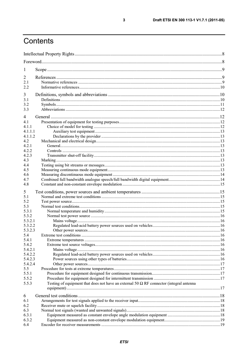
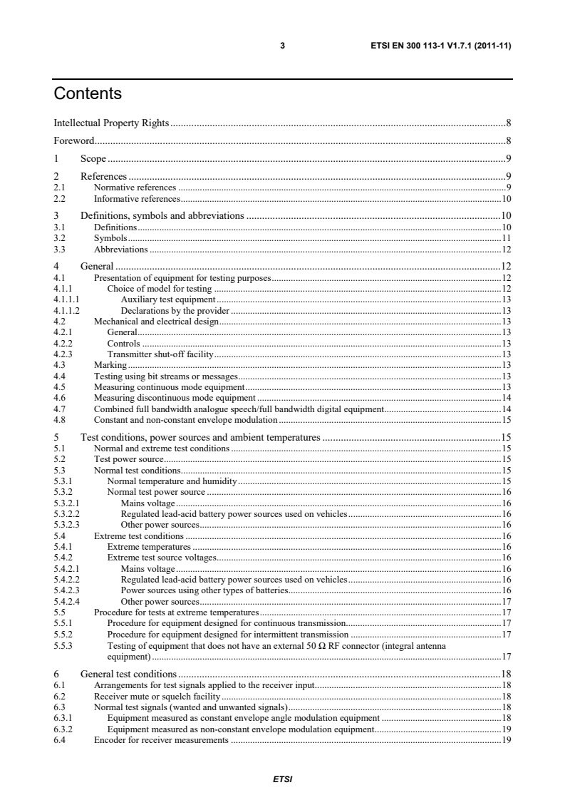
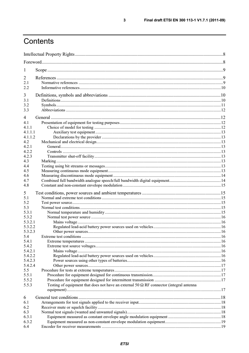
Contents
Intellectual Property Rights . 8
Foreword . 8
1 Scope . 9
2 References . 9
2.1 Normative references . 9
2.2 Informative references . 10
3 Definitions, symbols and abbreviations . 10
3.1 Definitions . 10
3.2 Symbols . 11
3.3 Abbreviations . 12
4 General . 12
4.1 Presentation of equipment for testing purposes . 12
4.1.1 Choice of model for testing . 12
4.1.1.1 Auxiliary test equipment . 13
4.1.1.2 Declarations by the provider . 13
4.2 Mechanical and electrical design . 13
4.2.1 General . 13
4.2.2 Controls . 13
4.2.3 Transmitter shut-off facility . 13
4.3 Marking . 13
4.4 Testing using bit streams or messages . 13
4.5 Measuring continuous mode equipment . 13
4.6 Measuring discontinuous mode equipment . 14
4.7 Combined full bandwidth analogue speech/full bandwidth digital equipment . 14
4.8 Constant and non-constant envelope modulation . 15
5 Test conditions, power sources and ambient temperatures . 15
5.1 Normal and extreme test conditions . 15
5.2 Test power source . 15
5.3 Normal test conditions . 15
5.3.1 Normal temperature and humidity . 15
5.3.2 Normal test power source . 16
5.3.2.1 Mains voltage . 16
5.3.2.2 Regulated lead-acid battery power sources used on vehicles . 16
5.3.2.3 Other power sources . 16
5.4 Extreme test conditions . 16
5.4.1 Extreme temperatures . 16
5.4.2 Extreme test source voltages . 16
5.4.2.1 Mains voltage . 16
5.4.2.2 Regulated lead-acid battery power sources used on vehicles . 16
5.4.2.3 Power sources using other types of batteries . 16
5.4.2.4 Other power sources . 17
5.5 Procedure for tests at extreme temperatures . 17
5.5.1 Procedure for equipment designed for continuous transmission. 17
5.5.2 Procedure for equipment designed for intermittent transmission . 17
5.5.3 Testing of equipment that does not have an external 50 Ω RF connector (integral antenna
equipment) . 17
6 General test conditions . 18
6.1 Arrangements for test signals applied to the receiver input . 18
6.2 Receiver mute or squelch facility . 18
6.3 Normal test signals (wanted and unwanted signals) . 18
6.3.1 Equipment measured as constant envelope angle modulation equipment . 18
6.3.2 Equipment measured as non-constant envelope modulation equipment . 19
6.4 Encoder for receiver measurements . 19
ETSI
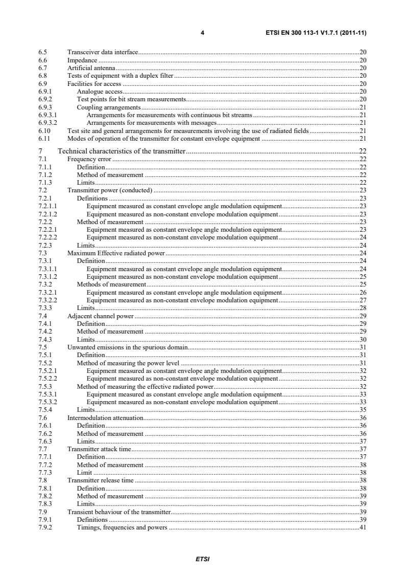
4 Draft ETSI EN 300 113-1 V1.7.1 (2011-05)
6.5 Transceiver data interface. 20
6.6 Impedance . 20
6.7 Artificial antenna . 20
6.8 Tests of equipment with a duplex filter . 20
6.9 Facilities for access . 20
6.9.1 Analogue access . 20
6.9.2 Test points for bit stream measurements. 20
6.9.3 Coupling arrangements . 21
6.9.3.1 Arrangements for measurements with continuous bit streams . 21
6.9.3.2 Arrangements for measurements with messages . 21
6.10 Test site and general arrangements for measurements involving the use of radiated fields . 21
6.11 Modes of operation of the transmitter for constant envelope equipment . 21
7 Technical characteristics of the transmitter . 22
7.1 Frequency error . 22
7.1.1 Definition . 22
7.1.2 Method of measurement . 22
7.1.3 Limits . 22
7.2 Transmitter power (conducted) . 23
7.2.1 Definitions . 23
7.2.1.1 Equipment measured as constant envelope angle modulation equipment . 23
7.2.1.2 Equipment measured as non-constant envelope modulation equipment . 23
7.2.2 Method of measurement . 23
7.2.2.1 Equipment measured as constant envelope angle modulation equipment . 23
7.2.2.2 Equipment measured as non-constant envelope modulation equipment . 24
7.2.3 Limits . 24
7.3 Maximum Effective radiated power . 24
7.3.1 Definition . 24
7.3.1.1 Equipment measured as constant envelope angle modulation equipment . 24
7.3.1.2 Equipment measured as non-constant envelope modulation equipment . 25
7.3.2 Methods of measurement . 25
7.3.2.1 Equipment measured as constant envelope angle modulation equipment . 26
7.3.2.2 Equipment measured as non-constant envelope modulation equipment . 27
7.3.3 Limits . 28
7.4 Adjacent channel power . 29
7.4.1 Definition . 29
7.4.2 Method of measurement . 29
7.4.3 Limits . 30
7.5 Unwanted emissions in the spurious domain. 31
7.5.1 Definition . 31
7.5.2 Method of measuring the power level . 31
7.5.2.1 Equipment measured as constant envelope angle modulation equipment . 32
7.5.2.2 Equipment measured as non-constant envelope modulation equipment . 32
7.5.3 Method of measuring the effective radiated power . 32
7.5.3.1 Equipment measured as constant envelope angle modulation equipment . 33
7.5.3.2 Equipment measured as non-constant envelope modulation equipment . 33
7.5.4 Limits . 35
7.6 Intermodulation attenuation. 36
7.6.1 Definition . 36
7.6.2 Method of measurement . 36
7.6.3 Limits . 37
7.7 Transmitter attack time . 37
7.7.1 Definition . 37
7.7.2 Method of measurement . 38
7.7.3 Limit . 38
7.8 Transmitter release time . 38
7.8.1 Definition . 38
7.8.2 Method of measurement . 39
7.8.3 Limits . 39
7.9 Transient behaviour of the transmitter . 39
7.9.1 Definitions . 39
7.9.2 Timings, frequencies and powers . 41
ETSI
5 Draft ETSI EN 300 113-1 V1.7.1 (2011-05)
7.9.3 Methods of measurement . 44
7.9.3.1 Time domain measurements of power and frequency . 44
7.9.3.2 Test arrangement and characteristics of the FM modulation meter . 45
7.9.3.3 Adjacent channel transient power measurements . 45
7.9.3.3.1 Definition. 45
7.9.3.3.2 Measurement method for constant envelope angle modulation equipment . 45
7.9.3.3.3 Measurement method for non-constant envelope modulation equipment . 46
7.9.3.3.4 Alternative measurement method using a spectrum analyser . 47
7.9.3.4 Characteristics of the adjacent channel transient power measuring device . 48
7.9.4 Limits . 48
7.9.4.1 Time domain analysis of power and frequency for constant envelope transmissions . 49
7.9.4.2 Adjacent and alternate channel transient power . 49
7.9.4.2.1 Equipment measured as constant envelope angle modulation equipment . 49
7.9.4.2.2 Equipment measured as non-constant envelope modulation equipment . 49
8 Methods of measurement for receiver parameters . 50
8.1 Maximum usable sensitivity (conducted) . 50
8.1.1 Definition . 50
8.1.2 Method of measurement . 50
8.1.2.1 Method of measurement with continuous bit streams . 50
8.1.2.2 Method of measurement with messages . 51
8.1.2.3 Method of measurement with packets . 51
8.1.3 Limits . 52
8.2 Average usable sensitivity (field strength) . 52
8.2.1 Definition . 52
8.2.2 Method of measurement . 52
8.2.3 Limits . 53
8.3 Level of the wanted signal for the degradation measurements . 53
8.4 Error behaviour at high input levels . 54
8.4.1 Definition . 54
8.4.2 Method of measurement . 54
8.4.2.1 Method of measurement with continuous bit streams . 54
8.4.2.2 Method of measurement with messages . 54
8.4.2.3 Method of measurement with packets . 55
8.4.3 Limits . 55
8.5 Co-channel rejection. 55
8.5.1 Definition . 55
8.5.2 Method of measurement . 56
8.5.2.1 Method of measurement with continuous bit streams . 56
8.5.2.2 Method of measurement with messages . 57
8.5.2.3 Method of measurement with packets . 58
8.5.3 Limits . 58
8.6 Adjacent channel selectivity . 59
8.6.1 Definition . 59
8.6.2 Method of measurement . 59
8.6.2.1 Method of measurement with continuous bit streams . 59
8.6.2.2 Method of measurement with messages . 60
8.6.2.3 Method of measurement with packets . 61
8.6.3 Limits . 62
8.7 Spurious response rejection . 62
8.7.1 Definition . 62
8.7.2 Introduction to the method of measurement . 62
8.7.3 Method of search over the "limited frequency range" . 63
8.7.4 Method of measurement with continuous bit streams . 64
8.7.5 Method of measurement with messages . 64
8.7.6 Method of measurement with packets . 65
8.7.7 Limits . 66
8.8 Intermodulation response rejection . 66
8.8.1 Definition . 66
8.8.2 Method of measurement . 67
8.8.2.1 Method of measurement with continuous bit streams . 67
8.8.2.2 Method of measurement with messages . 68
ETSI
6 Draft ETSI EN 300 113-1 V1.7.1 (2011-05)
8.8.2.3 Method of measurement with packets . 69
8.8.3 Limits . 69
8.9 Blocking or desensitization . 70
8.9.1 Definition . 70
8.9.2 Method of measurement . 70
8.9.2.1 Method of measurement with continuous bit streams . 70
8.9.2.2 Method of measurement with messages . 71
8.9.2.3 Method of measurement with packets . 72
8.9.3 Limits . 72
8.10 Spurious radiations . 72
8.10.1 Definition . 72
8.10.2 Method of measuring the power level . 73
8.10.3 Method of measuring the effective radiated power . 74
8.10.4 Limits . 75
9 Duplex operation . 76
9.1 Receiver desensitization (with simultaneous transmission and reception) . 76
9.1.1 Definition . 76
9.1.2 Desensitization measured with continuous bit streams . 77
9.1.2.1 Method of measurement when the equipment has a duplex filter . 77
9.1.2.2 Method of measurement when the equipment has to operate with two antennas . 78
9.1.3 Limits . 79
9.2 Receiver spurious response rejection (with simultaneous transmission and reception) . 79
9.2.1 Definition . 79
9.2.2 Method of measurement . 79
9.2.3 Limits . 81
10 Measurement uncertainty . 81
Annex A (normative): Radiated measurement . 83
A.1 Test sites and general arrangements for measurements involving the use of radiated fields . 83
A.1.1 Anechoic chamber . 83
A.1.2 Anechoic chamber with a conductive ground plane . 84
A.1.3 Open Area Test Site (OATS) . 85
A.1.4 Test antenna . 86
A.1.5 Substitution antenna . 87
A.1.6 Measuring antenna . 87
A.2 Guidance on the use of radiation test sites . 87
A.2.1 Verification of the test site . 87
A.2.2 Preparation of the EUT . 87
A.2.3 Power supplies to the EUT . 87
A.2.4 Volume control setting for analogue speech tests . 88
A.2.5 Range length . 88
A.2.6 Site preparation . 89
A.3 Coupling of signals . 89
A.3.1 General . 89
A.3.2 Data Signals. 89
A.3.3 Speech and analogue signals . 89
A.3.3.1 Acoustic coupler description. 90
A.3.3.2 Calibration . 90
Annex B (normative): Specification for some particular measurement arrangements . 91
B.1 Power measuring receiver specification . 91
B.1.1 IF filter . 91
B.1.2 Attenuation indicator . 92
B.1.3 RMS value indicator . 92
B.1.4 Oscillator and amplifier . 92
B.2 Spectrum analyser specification . 93
B.3 Integrating and power summing device . 93
ETSI
7 Draft ETSI EN 300 113-1 V1.7.1 (2011-05)
Annex C (informative): Bibliography . 94
History . 95
ETSI
8 Draft ETSI EN 300 113-1 V1.7.1 (2011-05)
Intellectual Property Rights
IPRs essential or potentially essential to the present document may have been declared to ETSI. The information
pertaining to these essential IPRs, if any, is publicly available for ETSI members and non-members, and can be found
in ETSI SR 000 314: "Intellectual Property Rights (IPRs); Essential, or potentially Essential, IPRs notified to ETSI in
respect of ETSI standards", which is available from the ETSI Secretariat. Latest updates are available on the ETSI Web
server (http://webapp.etsi.org/IPR/home.asp).
Pursuant to the ETSI IPR Policy, no investigation, including IPR searches, has been carried out by ETSI. No guarantee
can be given as to the existence of other IPRs not referenced in ETSI SR 000 314 (or the updates on the ETSI Web
server) which are, or may be, or may become, essential to the present document.
Foreword
This draft European Standard (EN) has been produced by ETSI Technical Committee Electromagnetic compatibility
and Radio spectrum Matters (ERM), and is now submitted for the Public Enquiry phase of the ETSI standards Two-step
Approval Procedure.
The present document is part 1 of a multi-part deliverable covering the Electromagnetic compatibility and Radio
spectrum Matters (ERM); Land mobile service; Radio equipment intended for the transmission of data (and/or speech)
using constant or non-constant envelope modulation and having an antenna connector, as identified below:
Part 1: "Technical characteristics and methods of measurement";
Part 2: "Harmonized EN covering the essential requirements of article 3.2 of the R&TTE Directive".
Proposed national transposition dates
Date of latest announcement of this EN (doa): 3 months after ETSI publication
Date of latest publication of new National Standard
or endorsement of this EN (dop/e): 6 months after doa
Date of withdrawal of any conflicting National Standard (dow): 6 months after doa
ETSI
9 Draft ETSI EN 300 113-1 V1.7.1 (2011-05)
1 Scope
The present document covers the technical requirements for radio transmitters and receivers used in stations in the
Private Mobile Radio (PMR) service.
It applies to use in the land mobile service, operating on radio frequencies between 30 MHz and 1 GHz, with channel
separations of 12,5 kHz, 20 kHz and 25 kHz, intended for speech and/or data.
Table 1: Radiocommunications service frequency bands
Radiocommunications service frequency bands
Transmit 30 MHz to 1 000 MHz
Receive 30 MHz to 1 000 MHz
It applies to equipment for continuous and/or discontinuous transmission of data and/or digital speech.
The equipment comprises a transmitter and associated encoder and modulator and/or a receiver and associated
demodulator and decoder. The types of equipment covered by the present document are as follows:
• base station (equipment fitted with an antenna connector, intended for use in a fixed location);
• mobile station (equipment fitted with an antenna connector, normally used in a vehicle or as a transportable);
and
• those handportable stations:
a) fitted with an antenna connector; or
b) without an external antenna connector , but fitted with a permanent internal or a temporary internal 50 Ω
Radio Frequency (RF) connector which allows access to the transmitter output and the receiver input.
Handportable equipment without an external or internal RF connector and without the possibility of having a temporary
internal 50 Ω RF connector is not covered by the present document.
2 References
References are either specific (identified by date of publication and/or edition number or version number) or
non-specific. For specific references, only the cited version applies. For non-specific references, the latest version of the
reference document (including any amendments) applies.
Referenced documents which are not found to be publicly available in the expected location might be found at
http://docbox.etsi.org/Reference.
NOTE: While any hyperlinks included in this clause were valid at the time of publication ETSI cannot guarantee
their long term validity.
2.1 Normative references
The following referenced documents are necessary for the application of the present document.
[1] ETSI EN 300 086-1 (V1.4.1): "Electromagnetic compatibility and Radio spectrum Matters (ERM);
Land Mobile Service; Radio equipment with an internal or external RF connector intended
primarily for analogue speech; Part 1: Technical characteristics and methods of measurement".
[2] ETSI EN 300 390-1 (V1.2.1): "Electromagnetic compatibility and Radio spectrum Matters (ERM);
Land Mobile Service; Radio equipment intended for the transmission of data (and speech) and
using an integral antenna; Part 1: Technical characteristics and test conditions".
ETSI
10 Draft ETSI EN 300 113-1 V1.7.1 (2011-05)
[3] ETSI TR 100 028 (V1.4.1) (all parts): "Electromagnetic compatibility and Radio spectrum Matters
(ERM); Uncertainties in the measurement of mobile radio equipment characteristics".
[4] ITU-T Recommendation O.153: "Basic parameters for the measurement of error performance at
bit rates below the primary rate".
[5] ANSI C63.5-2006: "American National Standard for Calibration of Antennas Used for Radiated
Emission Measurements in Electro Magnetic Interference".
[6] IEC 60489-3 (1988): "Methods of measurement for radio equipment used in the mobile services.
Part 3: Receivers for A3E or F3E emissions".
[7] CEPT/ERC/REC 74-01E: "Unwanted emissions in the spurious domain". (Siófok 1998,
Nice 1999, Sesimbra 2002, Hradec Kralove 2005).
[8] ETSI EN 300 793 (V1.1.1): "Electromagnetic compatibility and Radio spectrum Matters (ERM);
Land mobile service; Presentation of equipment for type testing".
2.2 Informative references
The following referenced documents are not necessary for the application of the present document but they assist the
user with regard to a particular subject area.
[i.1] ETSI TR 102 273 (V1.2.1) (all parts): "Electromagnetic compatibility and Radio spectrum Matters
(ERM); Improvement on
...
European Standard
Electromagnetic compatibility
and Radio spectrum Matters (ERM);
Land mobile service;
Radio equipment intended for the transmission
of data (and/or speech) using constant or non-constant
envelope modulation and having an antenna connector;
Part 1: Technical characteristics and
methods of measurement
2 ETSI EN 300 113-1 V1.7.1 (2011-11)
Reference
REN/ERM-TGDMR-296-1
Keywords
antenna, data, mobile, PMR, radio, speech
ETSI
650 Route des Lucioles
F-06921 Sophia Antipolis Cedex - FRANCE
Tel.: +33 4 92 94 42 00 Fax: +33 4 93 65 47 16
Siret N° 348 623 562 00017 - NAF 742 C
Association à but non lucratif enregistrée à la
Sous-Préfecture de Grasse (06) N° 7803/88
Important notice
Individual copies of the present document can be downloaded from:
http://www.etsi.org
The present document may be made available in more than one electronic version or in print. In any case of existing or
perceived difference in contents between such versions, the reference version is the Portable Document Format (PDF).
In case of dispute, the reference shall be the printing on ETSI printers of the PDF version kept on a specific network drive
within ETSI Secretariat.
Users of the present document should be aware that the document may be subject to revision or change of status.
Information on the current status of this and other ETSI documents is available at
http://portal.etsi.org/tb/status/status.asp
If you find errors in the present document, please send your comment to one of the following services:
http://portal.etsi.org/chaircor/ETSI_support.asp
Copyright Notification
No part may be reproduced except as authorized by written permission.
The copyright and the foregoing restriction extend to reproduction in all media.
© European Telecommunications Standards Institute 2011.
All rights reserved.
TM TM TM
DECT , PLUGTESTS , UMTS and the ETSI logo are Trade Marks of ETSI registered for the benefit of its Members.
TM
3GPP and LTE™ are Trade Marks of ETSI registered for the benefit of its Members and
of the 3GPP Organizational Partners.
GSM® and the GSM logo are Trade Marks registered and owned by the GSM Association.
ETSI
3 ETSI EN 300 113-1 V1.7.1 (2011-11)
Contents
Intellectual Property Rights . 8
Foreword . 8
1 Scope . 9
2 References . 9
2.1 Normative references . 9
2.2 Informative references . 10
3 Definitions, symbols and abbreviations . 10
3.1 Definitions . 10
3.2 Symbols . 11
3.3 Abbreviations . 12
4 General . 12
4.1 Presentation of equipment for testing purposes . 12
4.1.1 Choice of model for testing . 12
4.1.1.1 Auxiliary test equipment . 13
4.1.1.2 Declarations by the provider . 13
4.2 Mechanical and electrical design . 13
4.2.1 General . 13
4.2.2 Controls . 13
4.2.3 Transmitter shut-off facility . 13
4.3 Marking . 13
4.4 Testing using bit streams or messages . 13
4.5 Measuring continuous mode equipment . 13
4.6 Measuring discontinuous mode equipment . 14
4.7 Combined full bandwidth analogue speech/full bandwidth digital equipment . 14
4.8 Constant and non-constant envelope modulation . 15
5 Test conditions, power sources and ambient temperatures . 15
5.1 Normal and extreme test conditions . 15
5.2 Test power source . 15
5.3 Normal test conditions . 15
5.3.1 Normal temperature and humidity . 15
5.3.2 Normal test power source . 16
5.3.2.1 Mains voltage . 16
5.3.2.2 Regulated lead-acid battery power sources used on vehicles . 16
5.3.2.3 Other power sources . 16
5.4 Extreme test conditions . 16
5.4.1 Extreme temperatures . 16
5.4.2 Extreme test source voltages . 16
5.4.2.1 Mains voltage . 16
5.4.2.2 Regulated lead-acid battery power sources used on vehicles . 16
5.4.2.3 Power sources using other types of batteries . 16
5.4.2.4 Other power sources . 17
5.5 Procedure for tests at extreme temperatures . 17
5.5.1 Procedure for equipment designed for continuous transmission. 17
5.5.2 Procedure for equipment designed for intermittent transmission . 17
5.5.3 Testing of equipment that does not have an external 50 Ω RF connector (integral antenna
equipment) . 17
6 General test conditions . 18
6.1 Arrangements for test signals applied to the receiver input . 18
6.2 Receiver mute or squelch facility . 18
6.3 Normal test signals (wanted and unwanted signals) . 18
6.3.1 Equipment measured as constant envelope angle modulation equipment . 18
6.3.2 Equipment measured as non-constant envelope modulation equipment . 19
6.4 Encoder for receiver measurements . 19
ETSI
4 ETSI EN 300 113-1 V1.7.1 (2011-11)
6.5 Transceiver data interface. 20
6.6 Impedance . 20
6.7 Artificial antenna . 20
6.8 Tests of equipment with a duplex filter . 20
6.9 Facilities for access . 20
6.9.1 Analogue access . 20
6.9.2 Test points for bit stream measurements. 20
6.9.3 Coupling arrangements . 21
6.9.3.1 Arrangements for measurements with continuous bit streams . 21
6.9.3.2 Arrangements for measurements with messages . 21
6.10 Test site and general arrangements for measurements involving the use of radiated fields . 21
6.11 Modes of operation of the transmitter for constant envelope equipment . 21
7 Technical characteristics of the transmitter . 22
7.1 Frequency error . 22
7.1.1 Definition . 22
7.1.2 Method of measurement . 22
7.1.3 Limits . 22
7.2 Transmitter power (conducted) . 23
7.2.1 Definitions . 23
7.2.1.1 Equipment measured as constant envelope angle modulation equipment . 23
7.2.1.2 Equipment measured as non-constant envelope modulation equipment . 23
7.2.2 Method of measurement . 23
7.2.2.1 Equipment measured as constant envelope angle modulation equipment . 23
7.2.2.2 Equipment measured as non-constant envelope modulation equipment . 24
7.2.3 Limits . 24
7.3 Maximum Effective radiated power . 24
7.3.1 Definition . 24
7.3.1.1 Equipment measured as constant envelope angle modulation equipment . 24
7.3.1.2 Equipment measured as non-constant envelope modulation equipment . 25
7.3.2 Methods of measurement . 25
7.3.2.1 Equipment measured as constant envelope angle modulation equipment . 26
7.3.2.2 Equipment measured as non-constant envelope modulation equipment . 27
7.3.3 Limits . 28
7.4 Adjacent channel power . 29
7.4.1 Definition . 29
7.4.2 Method of measurement . 29
7.4.3 Limits . 30
7.5 Unwanted emissions in the spurious domain. 31
7.5.1 Definition . 31
7.5.2 Method of measuring the power level . 31
7.5.2.1 Equipment measured as constant envelope angle modulation equipment . 32
7.5.2.2 Equipment measured as non-constant envelope modulation equipment . 32
7.5.3 Method of measuring the effective radiated power . 32
7.5.3.1 Equipment measured as constant envelope angle modulation equipment . 33
7.5.3.2 Equipment measured as non-constant envelope modulation equipment . 33
7.5.4 Limits . 35
7.6 Intermodulation attenuation. 36
7.6.1 Definition . 36
7.6.2 Method of measurement . 36
7.6.3 Limits . 37
7.7 Transmitter attack time . 37
7.7.1 Definition . 37
7.7.2 Method of measurement . 38
7.7.3 Limit . 38
7.8 Transmitter release time . 38
7.8.1 Definition . 38
7.8.2 Method of measurement . 39
7.8.3 Limits . 39
7.9 Transient behaviour of the transmitter . 39
7.9.1 Definitions . 39
7.9.2 Timings, frequencies and powers . 41
ETSI
5 ETSI EN 300 113-1 V1.7.1 (2011-11)
7.9.3 Methods of measurement . 44
7.9.3.1 Time domain measurements of power and frequency . 44
7.9.3.2 Test arrangement and characteristics of the FM modulation meter . 45
7.9.3.3 Adjacent channel transient power measurements . 45
7.9.3.3.1 Definition. 45
7.9.3.3.2 Measurement method for constant envelope angle modulation equipment . 45
7.9.3.3.3 Measurement method for non-constant envelope modulation equipment . 46
7.9.3.3.4 Alternative measurement method using a spectrum analyser . 47
7.9.3.4 Characteristics of the adjacent channel transient power measuring device . 48
7.9.4 Limits . 48
7.9.4.1 Time domain analysis of power and frequency for constant envelope transmissions . 49
7.9.4.2 Adjacent and alternate channel transient power . 49
7.9.4.2.1 Equipment measured as constant envelope angle modulation equipment . 49
7.9.4.2.2 Equipment measured as non-constant envelope modulation equipment . 49
8 Methods of measurement for receiver parameters . 50
8.1 Maximum usable sensitivity (conducted) . 50
8.1.1 Definition . 50
8.1.2 Method of measurement . 50
8.1.2.1 Method of measurement with continuous bit streams . 50
8.1.2.2 Method of measurement with messages . 51
8.1.2.3 Method of measurement with packets . 51
8.1.3 Limits . 52
8.2 Average usable sensitivity (field strength) . 52
8.2.1 Definition . 52
8.2.2 Method of measurement . 52
8.2.3 Limits . 53
8.3 Level of the wanted signal for the degradation measurements . 53
8.4 Error behaviour at high input levels . 54
8.4.1 Definition . 54
8.4.2 Method of measurement . 54
8.4.2.1 Method of measurement with continuous bit streams . 54
8.4.2.2 Method of measurement with messages . 54
8.4.2.3 Method of measurement with packets . 55
8.4.3 Limits . 55
8.5 Co-channel rejection. 55
8.5.1 Definition . 55
8.5.2 Method of measurement . 56
8.5.2.1 Method of measurement with continuous bit streams . 56
8.5.2.2 Method of measurement with messages . 57
8.5.2.3 Method of measurement with packets . 58
8.5.3 Limits . 58
8.6 Adjacent channel selectivity . 59
8.6.1 Definition . 59
8.6.2 Method of measurement . 59
8.6.2.1 Method of measurement with continuous bit streams . 59
8.6.2.2 Method of measurement with messages . 60
8.6.2.3 Method of measurement with packets . 61
8.6.3 Limits . 62
8.7 Spurious response rejection . 62
8.7.1 Definition . 62
8.7.2 Introduction to the method of measurement . 62
8.7.3 Method of search over the "limited frequency range" . 63
8.7.4 Method of measurement with continuous bit streams . 64
8.7.5 Method of measurement with messages . 64
8.7.6 Method of measurement with packets . 65
8.7.7 Limits . 66
8.8 Intermodulation response rejection . 66
8.8.1 Definition . 66
8.8.2 Method of measurement . 67
8.8.2.1 Method of measurement with continuous bit streams . 67
8.8.2.2 Method of measurement with messages . 68
ETSI
6 ETSI EN 300 113-1 V1.7.1 (2011-11)
8.8.2.3 Method of measurement with packets . 69
8.8.3 Limits . 69
8.9 Blocking or desensitization . 70
8.9.1 Definition . 70
8.9.2 Method of measurement . 70
8.9.2.1 Method of measurement with continuous bit streams . 70
8.9.2.2 Method of measurement with messages . 71
8.9.2.3 Method of measurement with packets . 72
8.9.3 Limits . 72
8.10 Spurious radiations . 72
8.10.1 Definition . 72
8.10.2 Method of measuring the power level . 73
8.10.3 Method of measuring the effective radiated power . 74
8.10.4 Limits . 75
9 Duplex operation . 76
9.1 Receiver desensitization (with simultaneous transmission and reception) . 76
9.1.1 Definition . 76
9.1.2 Desensitization measured with continuous bit streams . 77
9.1.2.1 Method of measurement when the equipment has a duplex filter . 77
9.1.2.2 Method of measurement when the equipment has to operate with two antennas . 78
9.1.3 Limits . 79
9.2 Receiver spurious response rejection (with simultaneous transmission and reception) . 79
9.2.1 Definition . 79
9.2.2 Method of measurement . 79
9.2.3 Limits . 81
10 Measurement uncertainty . 81
Annex A (normative): Radiated measurement . 83
A.1 Test sites and general arrangements for measurements involving the use of radiated fields . 83
A.1.1 Anechoic chamber . 83
A.1.2 Anechoic chamber with a conductive ground plane . 84
A.1.3 Open Area Test Site (OATS) . 85
A.1.4 Test antenna . 86
A.1.5 Substitution antenna . 87
A.1.6 Measuring antenna . 87
A.2 Guidance on the use of radiation test sites . 87
A.2.1 Verification of the test site . 87
A.2.2 Preparation of the EUT . 87
A.2.3 Power supplies to the EUT . 87
A.2.4 Volume control setting for analogue speech tests . 88
A.2.5 Range length . 88
A.2.6 Site preparation . 89
A.3 Coupling of signals . 89
A.3.1 General . 89
A.3.2 Data Signals. 89
A.3.3 Speech and analogue signals . 89
A.3.3.1 Acoustic coupler description. 90
A.3.3.2 Calibration . 90
Annex B (normative): Specification for some particular measurement arrangements . 91
B.1 Power measuring receiver specification . 91
B.1.1 IF filter . 91
B.1.2 Attenuation indicator . 92
B.1.3 RMS value indicator . 92
B.1.4 Oscillator and amplifier . 92
B.2 Spectrum analyser specification . 93
B.3 Integrating and power summing device . 93
ETSI
7 ETSI EN 300 113-1 V1.7.1 (2011-11)
Annex C (informative): Bibliography . 94
History . 95
ETSI
8 ETSI EN 300 113-1 V1.7.1 (2011-11)
Intellectual Property Rights
IPRs essential or potentially essential to the present document may have been declared to ETSI. The information
pertaining to these essential IPRs, if any, is publicly available for ETSI members and non-members, and can be found
in ETSI SR 000 314: "Intellectual Property Rights (IPRs); Essential, or potentially Essential, IPRs notified to ETSI in
respect of ETSI standards", which is available from the ETSI Secretariat. Latest updates are available on the ETSI Web
server (http://ipr.etsi.org).
Pursuant to the ETSI IPR Policy, no investigation, including IPR searches, has been carried out by ETSI. No guarantee
can be given as to the existence of other IPRs not referenced in ETSI SR 000 314 (or the updates on the ETSI Web
server) which are, or may be, or may become, essential to the present document.
Foreword
This European Standard (EN) has been produced by ETSI Technical Committee Electromagnetic compatibility and
Radio spectrum Matters (ERM).
The present document is part 1 of a multi-part deliverable covering the Electromagnetic compatibility and Radio
spectrum Matters (ERM); Land mobile service; Radio equipment intended for the transmission of data (and/or speech)
using constant or non-constant envelope modulation and having an antenna connector, as identified below:
Part 1: "Technical characteristics and methods of measurement";
Part 2: "Harmonized EN covering the essential requirements of article 3.2 of the R&TTE Directive".
National transposition dates
Date of adoption of this EN: 21 November 2011
Date of latest announcement of this EN (doa): 29 February 2012
Date of latest publication of new National Standard
or endorsement of this EN (dop/e): 31 August 2012
Date of withdrawal of any conflicting National Standard (dow): 31 August 2012
ETSI
9 ETSI EN 300 113-1 V1.7.1 (2011-11)
1 Scope
The present document covers the technical requirements for radio transmitters and receivers used in stations in the
Private Mobile Radio (PMR) service.
It applies to use in the land mobile service, operating on radio frequencies between 30 MHz and 1 GHz, with channel
separations of 12,5 kHz, 20 kHz and 25 kHz, intended for speech and/or data.
Table 1: Radiocommunications service frequency bands
Radiocommunications service frequency bands
Transmit 30 MHz to 1 000 MHz
Receive 30 MHz to 1 000 MHz
It applies to equipment for continuous and/or discontinuous transmission of data and/or digital speech.
The equipment comprises a transmitter and associated encoder and modulator and/or a receiver and associated
demodulator and decoder. The types of equipment covered by the present document are as follows:
• base station (equipment fitted with an antenna connector, intended for use in a fixed location);
• mobile station (equipment fitted with an antenna connector, normally used in a vehicle or as a transportable);
and
• those handportable stations:
a) fitted with an antenna connector; or
b) without an external antenna connector , but fitted with a permanent internal or a temporary internal 50 Ω
Radio Frequency (RF) connector which allows access to the transmitter output and the receiver input.
Handportable equipment without an external or internal RF connector and without the possibility of having a temporary
internal 50 Ω RF connector is not covered by the present document.
2 References
References are either specific (identified by date of publication and/or edition number or version number) or
non-specific. For specific references, only the cited version applies. For non-specific references, the latest version of the
reference document (including any amendments) applies.
Referenced documents which are not found to be publicly available in the expected location might be found at
http://docbox.etsi.org/Reference.
NOTE: While any hyperlinks included in this clause were valid at the time of publication ETSI cannot guarantee
their long term validity.
2.1 Normative references
The following referenced documents are necessary for the application of the present document.
[1] ETSI EN 300 086-1 (V1.4.1): "Electromagnetic compatibility and Radio spectrum Matters (ERM);
Land Mobile Service; Radio equipment with an internal or external RF connector intended
primarily for analogue speech; Part 1: Technical characteristics and methods of measurement".
[2] ETSI EN 300 390-1 (V1.2.1): "Electromagnetic compatibility and Radio spectrum Matters (ERM);
Land Mobile Service; Radio equipment intended for the transmission of data (and speech) and
using an integral antenna; Part 1: Technical characteristics and test conditions".
ETSI
10 ETSI EN 300 113-1 V1.7.1 (2011-11)
[3] ETSI TR 100 028 (V1.4.1) (all parts): "Electromagnetic compatibility and Radio spectrum Matters
(ERM); Uncertainties in the measurement of mobile radio equipment characteristics".
[4] ITU-T Recommendation O.153: "Basic parameters for the measurement of error performance at
bit rates below the primary rate".
[5] ANSI C63.5-2006: "American National Standard for Calibration of Antennas Used for Radiated
Emission Measurements in Electro Magnetic Interference".
[6] IEC 60489-3 (1988): "Methods of measurement for radio equipment used in the mobile services.
Part 3: Receivers for A3E or F3E emissions".
[7] CEPT/ERC/REC 74-01E: "Unwanted emissions in the spurious domain" (Siófok 1998, Nice 1999,
Sesimbra 2002, Hradec Kralove 2005).
[8] ETSI EN 300 793 (V1.1.1): "Electromagnetic compatibility and Radio spectrum Matters (ERM);
Land mobile service; Presentation of equipment for type testing".
2.2 Informative references
The following referenced documents are not necessary for the application of the present document but they assist the
user with regard to a particular subject area.
[i.1] ETSI TR 102 273 (V1.2.1) (all parts): "Electromagnetic compatibility and Radio spectrum Matters
(ERM); Improvement on Radiated Methods of Measurement (using test site) and evaluation of the
corresponding measurement uncertainties".
3 Definitions, symbols and abbreviations
3.1 Definitions
For the purposes of the present document, the following terms and definitions apply:
50 Ω: 50 ohm non-reactive impeda
...
Final draft ETSI EN 300 113-1 V1.7.1 (2011-09)
European Standard
Electromagnetic compatibility
and Radio spectrum Matters (ERM);
Land mobile service;
Radio equipment intended for the transmission
of data (and/or speech) using constant or non-constant
envelope modulation and having an antenna connector;
Part 1: Technical characteristics and
methods of measurement
2 Final draft ETSI EN 300 113-1 V1.7.1 (2011-09)
Reference
REN/ERM-TGDMR-296-1
Keywords
antenna, data, mobile, PMR, radio, speech
ETSI
650 Route des Lucioles
F-06921 Sophia Antipolis Cedex - FRANCE
Tel.: +33 4 92 94 42 00 Fax: +33 4 93 65 47 16
Siret N° 348 623 562 00017 - NAF 742 C
Association à but non lucratif enregistrée à la
Sous-Préfecture de Grasse (06) N° 7803/88
Important notice
Individual copies of the present document can be downloaded from:
http://www.etsi.org
The present document may be made available in more than one electronic version or in print. In any case of existing or
perceived difference in contents between such versions, the reference version is the Portable Document Format (PDF).
In case of dispute, the reference shall be the printing on ETSI printers of the PDF version kept on a specific network drive
within ETSI Secretariat.
Users of the present document should be aware that the document may be subject to revision or change of status.
Information on the current status of this and other ETSI documents is available at
http://portal.etsi.org/tb/status/status.asp
If you find errors in the present document, please send your comment to one of the following services:
http://portal.etsi.org/chaircor/ETSI_support.asp
Copyright Notification
No part may be reproduced except as authorized by written permission.
The copyright and the foregoing restriction extend to reproduction in all media.
© European Telecommunications Standards Institute 2011.
All rights reserved.
TM TM TM
DECT , PLUGTESTS , UMTS and the ETSI logo are Trade Marks of ETSI registered for the benefit of its Members.
TM
3GPP and LTE™ are Trade Marks of ETSI registered for the benefit of its Members and
of the 3GPP Organizational Partners.
GSM® and the GSM logo are Trade Marks registered and owned by the GSM Association.
ETSI
3 Final draft ETSI EN 300 113-1 V1.7.1 (2011-09)
Contents
Intellectual Property Rights . 8
Foreword . 8
1 Scope . 9
2 References . 9
2.1 Normative references . 9
2.2 Informative references . 10
3 Definitions, symbols and abbreviations . 10
3.1 Definitions . 10
3.2 Symbols . 11
3.3 Abbreviations . 12
4 General . 12
4.1 Presentation of equipment for testing purposes . 12
4.1.1 Choice of model for testing . 12
4.1.1.1 Auxiliary test equipment . 13
4.1.1.2 Declarations by the provider . 13
4.2 Mechanical and electrical design . 13
4.2.1 General . 13
4.2.2 Controls . 13
4.2.3 Transmitter shut-off facility . 13
4.3 Marking . 13
4.4 Testing using bit streams or messages . 13
4.5 Measuring continuous mode equipment . 13
4.6 Measuring discontinuous mode equipment . 14
4.7 Combined full bandwidth analogue speech/full bandwidth digital equipment . 14
4.8 Constant and non-constant envelope modulation . 15
5 Test conditions, power sources and ambient temperatures . 15
5.1 Normal and extreme test conditions . 15
5.2 Test power source . 15
5.3 Normal test conditions . 15
5.3.1 Normal temperature and humidity . 15
5.3.2 Normal test power source . 16
5.3.2.1 Mains voltage . 16
5.3.2.2 Regulated lead-acid battery power sources used on vehicles . 16
5.3.2.3 Other power sources . 16
5.4 Extreme test conditions . 16
5.4.1 Extreme temperatures . 16
5.4.2 Extreme test source voltages . 16
5.4.2.1 Mains voltage . 16
5.4.2.2 Regulated lead-acid battery power sources used on vehicles . 16
5.4.2.3 Power sources using other types of batteries . 16
5.4.2.4 Other power sources . 17
5.5 Procedure for tests at extreme temperatures . 17
5.5.1 Procedure for equipment designed for continuous transmission. 17
5.5.2 Procedure for equipment designed for intermittent transmission . 17
5.5.3 Testing of equipment that does not have an external 50 Ω RF connector (integral antenna
equipment) . 17
6 General test conditions . 18
6.1 Arrangements for test signals applied to the receiver input . 18
6.2 Receiver mute or squelch facility . 18
6.3 Normal test signals (wanted and unwanted signals) . 18
6.3.1 Equipment measured as constant envelope angle modulation equipment . 18
6.3.2 Equipment measured as non-constant envelope modulation equipment . 19
6.4 Encoder for receiver measurements . 19
ETSI
4 Final draft ETSI EN 300 113-1 V1.7.1 (2011-09)
6.5 Transceiver data interface. 20
6.6 Impedance . 20
6.7 Artificial antenna . 20
6.8 Tests of equipment with a duplex filter . 20
6.9 Facilities for access . 20
6.9.1 Analogue access . 20
6.9.2 Test points for bit stream measurements. 20
6.9.3 Coupling arrangements . 21
6.9.3.1 Arrangements for measurements with continuous bit streams . 21
6.9.3.2 Arrangements for measurements with messages . 21
6.10 Test site and general arrangements for measurements involving the use of radiated fields . 21
6.11 Modes of operation of the transmitter for constant envelope equipment . 21
7 Technical characteristics of the transmitter . 22
7.1 Frequency error . 22
7.1.1 Definition . 22
7.1.2 Method of measurement . 22
7.1.3 Limits . 22
7.2 Transmitter power (conducted) . 23
7.2.1 Definitions . 23
7.2.1.1 Equipment measured as constant envelope angle modulation equipment . 23
7.2.1.2 Equipment measured as non-constant envelope modulation equipment . 23
7.2.2 Method of measurement . 23
7.2.2.1 Equipment measured as constant envelope angle modulation equipment . 23
7.2.2.2 Equipment measured as non-constant envelope modulation equipment . 24
7.2.3 Limits . 24
7.3 Maximum Effective radiated power . 24
7.3.1 Definition . 24
7.3.1.1 Equipment measured as constant envelope angle modulation equipment . 24
7.3.1.2 Equipment measured as non-constant envelope modulation equipment . 25
7.3.2 Methods of measurement . 25
7.3.2.1 Equipment measured as constant envelope angle modulation equipment . 26
7.3.2.2 Equipment measured as non-constant envelope modulation equipment . 27
7.3.3 Limits . 28
7.4 Adjacent channel power . 29
7.4.1 Definition . 29
7.4.2 Method of measurement . 29
7.4.3 Limits . 30
7.5 Unwanted emissions in the spurious domain. 31
7.5.1 Definition . 31
7.5.2 Method of measuring the power level . 31
7.5.2.1 Equipment measured as constant envelope angle modulation equipment . 32
7.5.2.2 Equipment measured as non-constant envelope modulation equipment . 32
7.5.3 Method of measuring the effective radiated power . 32
7.5.3.1 Equipment measured as constant envelope angle modulation equipment . 33
7.5.3.2 Equipment measured as non-constant envelope modulation equipment . 33
7.5.4 Limits . 35
7.6 Intermodulation attenuation. 36
7.6.1 Definition . 36
7.6.2 Method of measurement . 36
7.6.3 Limits . 37
7.7 Transmitter attack time . 37
7.7.1 Definition . 37
7.7.2 Method of measurement . 38
7.7.3 Limit . 38
7.8 Transmitter release time . 38
7.8.1 Definition . 38
7.8.2 Method of measurement . 39
7.8.3 Limits . 39
7.9 Transient behaviour of the transmitter . 39
7.9.1 Definitions . 39
7.9.2 Timings, frequencies and powers . 41
ETSI
5 Final draft ETSI EN 300 113-1 V1.7.1 (2011-09)
7.9.3 Methods of measurement . 44
7.9.3.1 Time domain measurements of power and frequency . 44
7.9.3.2 Test arrangement and characteristics of the FM modulation meter . 45
7.9.3.3 Adjacent channel transient power measurements . 45
7.9.3.3.1 Definition. 45
7.9.3.3.2 Measurement method for constant envelope angle modulation equipment . 45
7.9.3.3.3 Measurement method for non-constant envelope modulation equipment . 46
7.9.3.3.4 Alternative measurement method using a spectrum analyser . 47
7.9.3.4 Characteristics of the adjacent channel transient power measuring device . 48
7.9.4 Limits . 48
7.9.4.1 Time domain analysis of power and frequency for constant envelope transmissions . 49
7.9.4.2 Adjacent and alternate channel transient power . 49
7.9.4.2.1 Equipment measured as constant envelope angle modulation equipment . 49
7.9.4.2.2 Equipment measured as non-constant envelope modulation equipment . 49
8 Methods of measurement for receiver parameters . 50
8.1 Maximum usable sensitivity (conducted) . 50
8.1.1 Definition . 50
8.1.2 Method of measurement . 50
8.1.2.1 Method of measurement with continuous bit streams . 50
8.1.2.2 Method of measurement with messages . 51
8.1.2.3 Method of measurement with packets . 51
8.1.3 Limits . 52
8.2 Average usable sensitivity (field strength) . 52
8.2.1 Definition . 52
8.2.2 Method of measurement . 52
8.2.3 Limits . 53
8.3 Level of the wanted signal for the degradation measurements . 53
8.4 Error behaviour at high input levels . 54
8.4.1 Definition . 54
8.4.2 Method of measurement . 54
8.4.2.1 Method of measurement with continuous bit streams . 54
8.4.2.2 Method of measurement with messages . 54
8.4.2.3 Method of measurement with packets . 55
8.4.3 Limits . 55
8.5 Co-channel rejection. 55
8.5.1 Definition . 55
8.5.2 Method of measurement . 56
8.5.2.1 Method of measurement with continuous bit streams . 56
8.5.2.2 Method of measurement with messages . 57
8.5.2.3 Method of measurement with packets . 58
8.5.3 Limits . 58
8.6 Adjacent channel selectivity . 59
8.6.1 Definition . 59
8.6.2 Method of measurement . 59
8.6.2.1 Method of measurement with continuous bit streams . 59
8.6.2.2 Method of measurement with messages . 60
8.6.2.3 Method of measurement with packets . 61
8.6.3 Limits . 62
8.7 Spurious response rejection . 62
8.7.1 Definition . 62
8.7.2 Introduction to the method of measurement . 62
8.7.3 Method of search over the "limited frequency range" . 63
8.7.4 Method of measurement with continuous bit streams . 64
8.7.5 Method of measurement with messages . 64
8.7.6 Method of measurement with packets . 65
8.7.7 Limits . 66
8.8 Intermodulation response rejection . 66
8.8.1 Definition . 66
8.8.2 Method of measurement . 67
8.8.2.1 Method of measurement with continuous bit streams . 67
8.8.2.2 Method of measurement with messages . 68
ETSI
6 Final draft ETSI EN 300 113-1 V1.7.1 (2011-09)
8.8.2.3 Method of measurement with packets . 69
8.8.3 Limits . 69
8.9 Blocking or desensitization . 70
8.9.1 Definition . 70
8.9.2 Method of measurement . 70
8.9.2.1 Method of measurement with continuous bit streams . 70
8.9.2.2 Method of measurement with messages . 71
8.9.2.3 Method of measurement with packets . 72
8.9.3 Limits . 72
8.10 Spurious radiations . 72
8.10.1 Definition . 72
8.10.2 Method of measuring the power level . 73
8.10.3 Method of measuring the effective radiated power . 74
8.10.4 Limits . 75
9 Duplex operation . 76
9.1 Receiver desensitization (with simultaneous transmission and reception) . 76
9.1.1 Definition . 76
9.1.2 Desensitization measured with continuous bit streams . 77
9.1.2.1 Method of measurement when the equipment has a duplex filter . 77
9.1.2.2 Method of measurement when the equipment has to operate with two antennas . 78
9.1.3 Limits . 79
9.2 Receiver spurious response rejection (with simultaneous transmission and reception) . 79
9.2.1 Definition . 79
9.2.2 Method of measurement . 79
9.2.3 Limits . 81
10 Measurement uncertainty . 81
Annex A (normative): Radiated measurement . 83
A.1 Test sites and general arrangements for measurements involving the use of radiated fields . 83
A.1.1 Anechoic chamber . 83
A.1.2 Anechoic chamber with a conductive ground plane . 84
A.1.3 Open Area Test Site (OATS) . 85
A.1.4 Test antenna . 86
A.1.5 Substitution antenna . 87
A.1.6 Measuring antenna . 87
A.2 Guidance on the use of radiation test sites . 87
A.2.1 Verification of the test site . 87
A.2.2 Preparation of the EUT . 87
A.2.3 Power supplies to the EUT . 87
A.2.4 Volume control setting for analogue speech tests . 88
A.2.5 Range length . 88
A.2.6 Site preparation . 89
A.3 Coupling of signals . 89
A.3.1 General . 89
A.3.2 Data Signals. 89
A.3.3 Speech and analogue signals . 89
A.3.3.1 Acoustic coupler description. 90
A.3.3.2 Calibration . 90
Annex B (normative): Specification for some particular measurement arrangements . 91
B.1 Power measuring receiver specification . 91
B.1.1 IF filter . 91
B.1.2 Attenuation indicator . 92
B.1.3 RMS value indicator . 92
B.1.4 Oscillator and amplifier . 92
B.2 Spectrum analyser specification . 93
B.3 Integrating and power summing device . 93
ETSI
7 Final draft ETSI EN 300 113-1 V1.7.1 (2011-09)
Annex C (informative): Bibliography . 94
History . 95
ETSI
8 Final draft ETSI EN 300 113-1 V1.7.1 (2011-09)
Intellectual Property Rights
IPRs essential or potentially essential to the present document may have been declared to ETSI. The information
pertaining to these essential IPRs, if any, is publicly available for ETSI members and non-members, and can be found
in ETSI SR 000 314: "Intellectual Property Rights (IPRs); Essential, or potentially Essential, IPRs notified to ETSI in
respect of ETSI standards", which is available from the ETSI Secretariat. Latest updates are available on the ETSI Web
server (http://ipr.etsi.org).
Pursuant to the ETSI IPR Policy, no investigation, including IPR searches, has been carried out by ETSI. No guarantee
can be given as to the existence of other IPRs not referenced in ETSI SR 000 314 (or the updates on the ETSI Web
server) which are, or may be, or may become, essential to the present document.
Foreword
This final draft European Standard (EN) has been produced by ETSI Technical Committee Electromagnetic
compatibility and Radio spectrum Matters (ERM), and is now submitted for the Vote phase of the ETSI standards
Two-step Approval Procedure.
The present document is part 1 of a multi-part deliverable covering the Electromagnetic compatibility and Radio
spectrum Matters (ERM); Land mobile service; Radio equipment intended for the transmission of data (and/or speech)
using constant or non-constant envelope modulation and having an antenna connector, as identified below:
Part 1: "Technical characteristics and methods of measurement";
Part 2: "Harmonized EN covering the essential requirements of article 3.2 of the R&TTE Directive".
Proposed national transposition dates
Date of latest announcement of this EN (doa): 3 months after ETSI publication
Date of latest publication of new National Standard
or endorsement of this EN (dop/e): 6 months after doa
Date of withdrawal of any conflicting National Standard (dow): 6 months after doa
ETSI
9 Final draft ETSI EN 300 113-1 V1.7.1 (2011-09)
1 Scope
The present document covers the technical requirements for radio transmitters and receivers used in stations in the
Private Mobile Radio (PMR) service.
It applies to use in the land mobile service, operating on radio frequencies between 30 MHz and 1 GHz, with channel
separations of 12,5 kHz, 20 kHz and 25 kHz, intended for speech and/or data.
Table 1: Radiocommunications service frequency bands
Radiocommunications service frequency bands
Transmit 30 MHz to 1 000 MHz
Receive 30 MHz to 1 000 MHz
It applies to equipment for continuous and/or discontinuous transmission of data and/or digital speech.
The equipment comprises a transmitter and associated encoder and modulator and/or a receiver and associated
demodulator and decoder. The types of equipment covered by the present document are as follows:
• base station (equipment fitted with an antenna connector, intended for use in a fixed location);
• mobile station (equipment fitted with an antenna connector, normally used in a vehicle or as a transportable);
and
• those handportable stations:
a) fitted with an antenna connector; or
b) without an external antenna connector , but fitted with a permanent internal or a temporary internal 50 Ω
Radio Frequency (RF) connector which allows access to the transmitter output and the receiver input.
Handportable equipment without an external or internal RF connector and without the possibility of having a temporary
internal 50 Ω RF connector is not covered by the present document.
2 References
References are either specific (identified by date of publication and/or edition number or version number) or
non-specific. For specific references, only the cited version applies. For non-specific references, the latest version of the
reference document (including any amendments) applies.
Referenced documents which are not found to be publicly available in the expected location might be found at
http://docbox.etsi.org/Reference.
NOTE: While any hyperlinks included in this clause were valid at the time of publication ETSI cannot guarantee
their long term validity.
2.1 Normative references
The following referenced documents are necessary for the application of the present document.
[1] ETSI EN 300 086-1 (V1.4.1): "Electromagnetic compatibility and Radio spectrum Matters (ERM);
Land Mobile Service; Radio equipment with an internal or external RF connector intended
primarily for analogue speech; Part 1: Technical characteristics and methods of measurement".
[2] ETSI EN 300 390-1 (V1.2.1): "Electromagnetic compatibility and Radio spectrum Matters (ERM);
Land Mobile Service; Radio equipment intended for the transmission of data (and speech) and
using an integral antenna; Part 1: Technical characteristics and test conditions".
ETSI
10 Final draft ETSI EN 300 113-1 V1.7.1 (2011-09)
[3] ETSI TR 100 028 (V1.4.1) (all parts): "Electromagnetic compatibility and Radio spectrum Matters
(ERM); Uncertainties in the measurement of mobile radio equipment characteristics".
[4] ITU-T Recommendation O.153: "Basic parameters for the measurement of error performance at
bit rates below the primary rate".
[5] ANSI C63.5-2006: "American National Standard for Calibration of Antennas Used for Radiated
Emission Measurements in Electro Magnetic Interference".
[6] IEC 60489-3 (1988): "Methods of measurement for radio equipment used in the mobile services.
Part 3: Receivers for A3E or F3E emissions".
[7] CEPT/ERC/REC 74-01E: "Unwanted emissions in the spurious domain". (Siófok 1998, Nice
1999, Sesimbra 2002, Hradec Kralove 2005).
[8] ETSI EN 300 793 (V1.1.1): "Electromagnetic compatibility and Radio spectrum Matters (ERM);
Land mobile service; Presentation of equipment for type testing".
2.2 Informative references
The following referenced documents are not necessary for the application of the present document but they assist the
user with regard to a particular subject area.
[i.1] ETSI TR 102 273 (V1.2.1) (all parts): "Electromagnetic compatibility and Radio spectrum Matters
(ERM); Improvement on Radiated Methods of Measurement (using test site) and evaluation of the
correspond
...
2003-01.Slovenski inštitut za standardizacijo. Razmnoževanje celote ali delov tega standarda ni dovoljeno.Electromagnetic compatibility and Radio spectrum Matters (ERM) - Land mobile service - Radio equipment intended for the transmission of data (and/or speech) using constant or non-constant envelope modulation and having an antenna connector - Part 1: Technical characteristics and methods of measurement33.100.01Elektromagnetna združljivost na splošnoElectromagnetic compatibility in general33.070.01Mobilni servisi na splošnoMobile services in general33.060.99Druga oprema za radijske komunikacijeOther equipment for radiocommunicationsICS:Ta slovenski standard je istoveten z:EN 300 113-1 Version 1.7.1SIST EN 300 113-1 V1.7.1:2012en01-februar-2012SIST EN 300 113-1 V1.7.1:2012SLOVENSKI
STANDARD
European Standard SIST EN 300 113-1 V1.7.1:2012
ETSI ETSI EN 300 113-1 V1.7.1 (2011-11) 2
Reference REN/ERM-TGDMR-296-1 Keywords antenna, data, mobile, PMR, radio, speech ETSI 650 Route des Lucioles F-06921 Sophia Antipolis Cedex - FRANCE
Tel.: +33 4 92 94 42 00
Fax: +33 4 93 65 47 16
Siret N° 348 623 562 00017 - NAF 742 C Association à but non lucratif enregistrée à la Sous-Préfecture de Grasse (06) N° 7803/88
Important notice Individual copies of the present document can be downloaded from: http://www.etsi.org The present document may be made available in more than one electronic version or in print. In any case of existing or perceived difference in contents between such versions, the reference version is the Portable Document Format (PDF). In case of dispute, the reference shall be the printing on ETSI printers of the PDF version kept on a specific network drive within ETSI Secretariat. Users of the present document should be aware that the document may be subject to revision or change of status. Information on the current status of this and other ETSI documents is available at http://portal.etsi.org/tb/status/status.asp If you find errors in the present document, please send your comment to one of the following services: http://portal.etsi.org/chaircor/ETSI_support.asp Copyright Notification No part may be reproduced except as authorized by written permission. The copyright and the foregoing restriction extend to reproduction in all media.
© European Telecommunications Standards Institute 2011. All rights reserved.
DECTTM, PLUGTESTSTM, UMTSTM and the ETSI logo are Trade Marks of ETSI registered for the benefit of its Members. 3GPPTM and LTE™ are Trade Marks of ETSI registered for the benefit of its Members and of the 3GPP Organizational Partners. GSM® and the GSM logo are Trade Marks registered and owned by the GSM Association. SIST EN 300 113-1 V1.7.1:2012
ETSI ETSI EN 300 113-1 V1.7.1 (2011-11) 3 Contents Intellectual Property Rights . 8 Foreword . 8 1 Scope . 9 2 References . 9 2.1 Normative references . 9 2.2 Informative references . 10 3 Definitions, symbols and abbreviations . 10 3.1 Definitions . 10 3.2 Symbols . 11 3.3 Abbreviations . 12 4 General . 12 4.1 Presentation of equipment for testing purposes . 12 4.1.1 Choice of model for testing . 12 4.1.1.1 Auxiliary test equipment . 13 4.1.1.2 Declarations by the provider . 13 4.2 Mechanical and electrical design . 13 4.2.1 General . 13 4.2.2 Controls . 13 4.2.3 Transmitter shut-off facility . 13 4.3 Marking . 13 4.4 Testing using bit streams or messages . 13 4.5 Measuring continuous mode equipment . 13 4.6 Measuring discontinuous mode equipment . 14 4.7 Combined full bandwidth analogue speech/full bandwidth digital equipment . 14 4.8 Constant and non-constant envelope modulation . 15 5 Test conditions, power sources and ambient temperatures . 15 5.1 Normal and extreme test conditions . 15 5.2 Test power source . 15 5.3 Normal test conditions . 15 5.3.1 Normal temperature and humidity . 15 5.3.2 Normal test power source . 16 5.3.2.1 Mains voltage . 16 5.3.2.2 Regulated lead-acid battery power sources used on vehicles . 16 5.3.2.3 Other power sources . 16 5.4 Extreme test conditions . 16 5.4.1 Extreme temperatures . 16 5.4.2 Extreme test source voltages . 16 5.4.2.1 Mains voltage . 16 5.4.2.2 Regulated lead-acid battery power sources used on vehicles . 16 5.4.2.3 Power sources using other types of batteries . 16 5.4.2.4 Other power sources . 17 5.5 Procedure for tests at extreme temperatures . 17 5.5.1 Procedure for equipment designed for continuous transmission. 17 5.5.2 Procedure for equipment designed for intermittent transmission . 17 5.5.3 Testing of equipment that does not have an external 50 Ω RF connector (integral antenna equipment) . 17 6 General test conditions . 18 6.1 Arrangements for test signals applied to the receiver input . 18 6.2 Receiver mute or squelch facility . 18 6.3 Normal test signals (wanted and unwanted signals) . 18 6.3.1 Equipment measured as constant envelope angle modulation equipment . 18 6.3.2 Equipment measured as non-constant envelope modulation equipment . 19 6.4 Encoder for receiver measurements . 19 SIST EN 300 113-1 V1.7.1:2012
ETSI ETSI EN 300 113-1 V1.7.1 (2011-11) 4 6.5 Transceiver data interface. 20 6.6 Impedance . 20 6.7 Artificial antenna . 20 6.8 Tests of equipment with a duplex filter . 20 6.9 Facilities for access . 20 6.9.1 Analogue access . 20 6.9.2 Test points for bit stream measurements. 20 6.9.3 Coupling arrangements . 21 6.9.3.1 Arrangements for measurements with continuous bit streams . 21 6.9.3.2 Arrangements for measurements with messages . 21 6.10 Test site and general arrangements for measurements involving the use of radiated fields . 21 6.11 Modes of operation of the transmitter for constant envelope equipment . 21 7 Technical characteristics of the transmitter . 22 7.1 Frequency error . 22 7.1.1 Definition . 22 7.1.2 Method of measurement . 22 7.1.3 Limits . 22 7.2 Transmitter power (conducted) . 23 7.2.1 Definitions . 23 7.2.1.1 Equipment measured as constant envelope angle modulation equipment . 23 7.2.1.2 Equipment measured as non-constant envelope modulation equipment . 23 7.2.2 Method of measurement . 23 7.2.2.1 Equipment measured as constant envelope angle modulation equipment . 23 7.2.2.2 Equipment measured as non-constant envelope modulation equipment . 24 7.2.3 Limits . 24 7.3 Maximum Effective radiated power . 24 7.3.1 Definition . 24 7.3.1.1 Equipment measured as constant envelope angle modulation equipment . 24 7.3.1.2 Equipment measured as non-constant envelope modulation equipment . 25 7.3.2 Methods of measurement . 25 7.3.2.1 Equipment measured as constant envelope angle modulation equipment . 26 7.3.2.2 Equipment measured as non-constant envelope modulation equipment . 27 7.3.3 Limits . 28 7.4 Adjacent channel power . 29 7.4.1 Definition . 29 7.4.2 Method of measurement . 29 7.4.3 Limits . 30 7.5 Unwanted emissions in the spurious domain. 31 7.5.1 Definition . 31 7.5.2 Method of measuring the power level . 31 7.5.2.1 Equipment measured as constant envelope angle modulation equipment . 32 7.5.2.2 Equipment measured as non-constant envelope modulation equipment . 32 7.5.3 Method of measuring the effective radiated power . 32 7.5.3.1 Equipment measured as constant envelope angle modulation equipment . 33 7.5.3.2 Equipment measured as non-constant envelope modulation equipment . 33 7.5.4 Limits . 35 7.6 Intermodulation attenuation. 36 7.6.1 Definition . 36 7.6.2 Method of measurement . 36 7.6.3 Limits . 37 7.7 Transmitter attack time . 37 7.7.1 Definition . 37 7.7.2 Method of measurement . 38 7.7.3 Limit . 38 7.8 Transmitter release time . 38 7.8.1 Definition . 38 7.8.2 Method of measurement . 39 7.8.3 Limits . 39 7.9 Transient behaviour of the transmitter . 39 7.9.1 Definitions . 39 7.9.2 Timings, frequencies and powers . 41 SIST EN 300 113-1 V1.7.1:2012
ETSI ETSI EN 300 113-1 V1.7.1 (2011-11) 5 7.9.3 Methods of measurement . 44 7.9.3.1 Time domain measurements of power and frequency . 44 7.9.3.2 Test arrangement and characteristics of the FM modulation meter . 45 7.9.3.3 Adjacent channel transient power measurements . 45 7.9.3.3.1 Definition. 45 7.9.3.3.2 Measurement method for constant envelope angle modulation equipment . 45 7.9.3.3.3 Measurement method for non-constant envelope modulation equipment . 46 7.9.3.3.4 Alternative measurement method using a spectrum analyser . 47 7.9.3.4 Characteristics of the adjacent channel transient power measuring device . 48 7.9.4 Limits . 48 7.9.4.1 Time domain analysis of power and frequency for constant envelope transmissions . 49 7.9.4.2 Adjacent and alternate channel transient power . 49 7.9.4.2.1 Equipment measured as constant envelope angle modulation equipment . 49 7.9.4.2.2 Equipment measured as non-constant envelope modulation equipment . 49 8 Methods of measurement for receiver parameters . 50 8.1 Maximum usable sensitivity (conducted) . 50 8.1.1 Definition . 50 8.1.2 Method of measurement . 50 8.1.2.1 Method of measurement with continuous bit streams . 50 8.1.2.2 Method of measurement with messages . 51 8.1.2.3 Method of measurement with packets . 51 8.1.3 Limits . 52 8.2 Average usable sensitivity (field strength) . 52 8.2.1 Definition . 52 8.2.2 Method of measurement . 52 8.2.3 Limits . 53 8.3 Level of the wanted signal for the degradation measurements . 53 8.4 Error behaviour at high input levels . 54 8.4.1 Definition . 54 8.4.2 Method of measurement . 54 8.4.2.1 Method of measurement with continuous bit streams . 54 8.4.2.2 Method of measurement with messages . 54 8.4.2.3 Method of measurement with packets . 55 8.4.3 Limits . 55 8.5 Co-channel rejection. 55 8.5.1 Definition . 55 8.5.2 Method of measurement . 56 8.5.2.1 Method of measurement with continuous bit streams . 56 8.5.2.2 Method of measurement with messages . 57 8.5.2.3 Method of measurement with packets . 58 8.5.3 Limits . 58 8.6 Adjacent channel selectivity . 59 8.6.1 Definition . 59 8.6.2 Method of measurement . 59 8.6.2.1 Method of measurement with continuous bit streams . 59 8.6.2.2 Method of measurement with messages . 60 8.6.2.3 Method of measurement with packets . 61 8.6.3 Limits . 62 8.7 Spurious response rejection . 62 8.7.1 Definition . 62 8.7.2 Introduction to the method of measurement . 62 8.7.3 Method of search over the "limited frequency range" . 63 8.7.4 Method of measurement with continuous bit streams . 64 8.7.5 Method of measurement with messages . 64 8.7.6 Method of measurement with packets . 65 8.7.7 Limits . 66 8.8 Intermodulation response rejection . 66 8.8.1 Definition . 66 8.8.2 Method of measurement . 67 8.8.2.1 Method of measurement with continuous bit streams . 67 8.8.2.2 Method of measurement with messages . 68 SIST EN 300 113-1 V1.7.1:2012
ETSI ETSI EN 300 113-1 V1.7.1 (2011-11) 6 8.8.2.3 Method of measurement with packets . 69 8.8.3 Limits . 69 8.9 Blocking or desensitization . 70 8.9.1 Definition . 70 8.9.2 Method of measurement . 70 8.9.2.1 Method of measurement with continuous bit streams . 70 8.9.2.2 Method of measurement with messages . 71 8.9.2.3 Method of measurement with packets . 72 8.9.3 Limits . 72 8.10 Spurious radiations . 72 8.10.1 Definition . 72 8.10.2 Method of measuring the power level . 73 8.10.3 Method of measuring the effective radiated power . 74 8.10.4 Limits . 75 9 Duplex operation . 76 9.1 Receiver desensitization (with simultaneous transmission and reception) . 76 9.1.1 Definition . 76 9.1.2 Desensitization measured with continuous bit streams . 77 9.1.2.1 Method of measurement when the equipment has a duplex filter . 77 9.1.2.2 Method of measurement when the equipment has to operate with two antennas . 78 9.1.3 Limits . 79 9.2 Receiver spurious response rejection (with simultaneous transmission and reception) . 79 9.2.1 Definition . 79 9.2.2 Method of measurement . 79 9.2.3 Limits . 81 10 Measurement uncertainty . 81 Annex A (normative): Radiated measurement . 83 A.1 Test sites and general arrangements for measurements involving the use of radiated fields . 83 A.1.1 Anechoic chamber . 83 A.1.2 Anechoic chamber with a conductive ground plane . 84 A.1.3 Open Area Test Site (OATS) . 85 A.1.4 Test antenna . 86 A.1.5 Substitution antenna . 87 A.1.6 Measuring antenna . 87 A.2 Guidance on the use of radiation test sites . 87 A.2.1 Verification of the test site . 87 A.2.2 Preparation of the EUT . 87 A.2.3 Power supplies to the EUT . 87 A.2.4 Volume control setting for analogue speech tests . 88 A.2.5 Range length . 88 A.2.6 Site preparation . 89 A.3 Coupling of signals . 89 A.3.1 General . 89 A.3.2 Data Signals. 89 A.3.3 Speech and analogue signals . 89 A.3.3.1 Acoustic coupler description. 90 A.3.3.2 Calibration . 90 Annex B (normative): Specification for some particular measurement arrangements . 91 B.1 Power measuring receiver specification . 91 B.1.1 IF filter . 91 B.1.2 Attenuation indicator . 92 B.1.3 RMS value indicator . 92 B.1.4 Oscillator and amplifier . 92 B.2 Spectrum analyser specification . 93 B.3 Integrating and power summing device . 93 SIST EN 300 113-1 V1.7.1:2012
ETSI ETSI EN 300 113-1 V1.7.1 (2011-11) 7 Annex C (informative): Bibliography . 94 History . 95
ETSI ETSI EN 300 113-1 V1.7.1 (2011-11) 8 Intellectual Property Rights IPRs essential or potentially essential to the present document may have been declared to ETSI. The information pertaining to these essential IPRs, if any, is publicly available for ETSI members and non-members, and can be found in ETSI SR 000 314: "Intellectual Property Rights (IPRs); Essential, or potentially Essential, IPRs notified to ETSI in respect of ETSI standards", which is available from the ETSI Secretariat. Latest updates are available on the ETSI Web server (http://ipr.etsi.org). Pursuant to the ETSI IPR Policy, no investigation, including IPR searches, has been carried out by ETSI. No guarantee can be given as to the existence of other IPRs not referenced in ETSI SR 000 314 (or the updates on the ETSI Web server) which are, or may be, or may become, essential to the present document. Foreword This European Standard (EN) has been produced by ETSI Technical Committee Electromagnetic compatibility and Radio spectrum Matters (ERM). The present document is part 1 of a multi-part deliverable covering the Electromagnetic compatibility and Radio spectrum Matters (ERM); Land mobile service; Radio equipment intended for the transmission of data (and/or speech) using constant or non-constant envelope modulation and having an antenna connector, as identified below: Part 1: "Technical characteristics and methods of measurement"; Part 2: "Harmonized EN covering the essential requirements of article 3.2 of the R&TTE Directive".
National transposition dates Date of adoption of this EN: 21 November 2011 Date of latest announcement of this EN (doa): 29 February 2012 Date of latest publication of new National Standard or endorsement of this EN (dop/e):
31 August 2012 Date of withdrawal of any conflicting National Standard (dow): 31 August 2012
ETSI ETSI EN 300 113-1 V1.7.1 (2011-11) 9 1 Scope The present document covers the technical requirements for radio transmitters and receivers used in stations in the Private Mobile Radio (PMR) service. It applies to use in the land mobile service, operating on radio frequencies between 30 MHz and 1 GHz, with channel separations of 12,5 kHz, 20 kHz and 25 kHz, intended for speech and/or data. Table 1: Radiocommunications service frequency bands
Radiocommunications service frequency bands Transmit 30 MHz to 1 000 MHz Receive 30 MHz to 1 000 MHz
It applies to equipment for continuous and/or discontinuous transmission of data and/or digital speech.
The equipment comprises a transmitter and associated encoder and modulator and/or a receiver and associated demodulator and decoder. The types of equipment covered by the present document are as follows: • base station (equipment fitted with an antenna connector, intended for use in a fixed location); • mobile station (equipment fitted with an antenna connector, normally used in a vehicle or as a transportable); and • those handportable stations: a) fitted with an antenna connector; or b) without an external antenna connector , but fitted with a permanent internal or a temporary internal 50 Ω Radio Frequency (RF) connector which allows access to the transmitter output and the receiver input. Handportable equipment without an external or internal RF connector and without the possibility of having a temporary internal 50 Ω RF connector is not covered by the present document. 2 References References are either specific (identified by date of publication and/or edition number or version number) or non-specific. For specific references, only the cited version applies. For non-specific references, the latest version of the reference document (including any amendments) applies. Referenced documents which are not found to be publicly available in the expected location might be found at http://docbox.etsi.org/Reference. NOTE: While any hyperlinks included in this clause were valid at the time of publication ETSI cannot guarantee their long term validity. 2.1 Normative references The following referenced documents are necessary for the application of the present document. [1] ETSI EN 300 086-1 (V1.4.1): "Electromagnetic compatibility and Radio spectrum Matters (ERM); Land Mobile Service; Radio equipment with an internal or external RF connector intended primarily for analogue speech; Part 1: Technical characteristics and methods of measurement". [2] ETSI EN 300 390-1 (V1.2.1): "Electromagnetic compatibility and Radio spectrum Matters (ERM); Land Mobile Service; Radio equipment intended for the transmission of data (and speech) and using an integral antenna; Part 1: Technical characteristics and test conditions". SIST EN 300 113-1 V1.7.1:2012
ETSI ETSI EN 300 113-1 V1.7.1 (2011-11) 10 [3] ETSI TR 100 028 (V1.4.1) (all parts): "Electromagnetic compatibility and Radio spectrum Matters (ERM); Uncertainties in the measurement of mobile radio equipment characteristics". [4] ITU-T Recommendation O.153: "Basic parameters for the measurement of error performance at bit rates below the primary rate". [5] ANSI C63.5-2006: "American National Standard for Calibration of Antennas Used for Radiated Emission Measurements in Electro Magnetic Interference". [6] IEC 60489-3 (1988): "Methods of measurement for radio equipment used in the mobile services. Part 3: Receivers for A3E or F3E emissions". [7] CEPT/ERC/REC 74-01E: "Unwanted emissions in the spurious domain" (Siófok 1998, Nice 1999, Sesimbra 2002, Hradec Kralove 2005). [8] ETSI EN 300 793 (V1.1.1): "Electromagnetic compatibility and Radio spectrum Matters (ERM); Land mobile service; Presentation of equipment for type testing". 2.2 Informative references The following referenced documents are not necessary for the application of the present document but they assist the user with regard to a particular subject area. [i.1] ETSI TR 102 273 (V1.2.1) (all parts): "Electromagnetic compatibility and Radio spectrum Matters (ERM); Improvement on Radiated Methods of Measurement (using test site) and evaluation of the correspond
...