

SIST EN 300 396-4 V1.4.1:2012
(Main)Terrestrial Trunked Radio (TETRA) - Technical requirements for Direct Mode Operation (DMO) - Part 4: Type 1 repeater air interface
- Abstract
REN/TETRA-08194
- Status
- Published
- Publication Date
- 10-Jan-2012
- Technical Committee
- MOC - Mobile Communications
- Current Stage
- 6060 - National Implementation/Publication (Adopted Project)
- Start Date
- 10-Jan-2012
- Due Date
- 16-Mar-2012
- Completion Date
- 11-Jan-2012
- Mandate
- BC-T-344
Buy Documents
en_30039604v010400o - Terrestrial Trunked Radio (TETRA); Technical requirements for Direct Mode Operation (DMO); Part 4: Type 1 repeater air interface
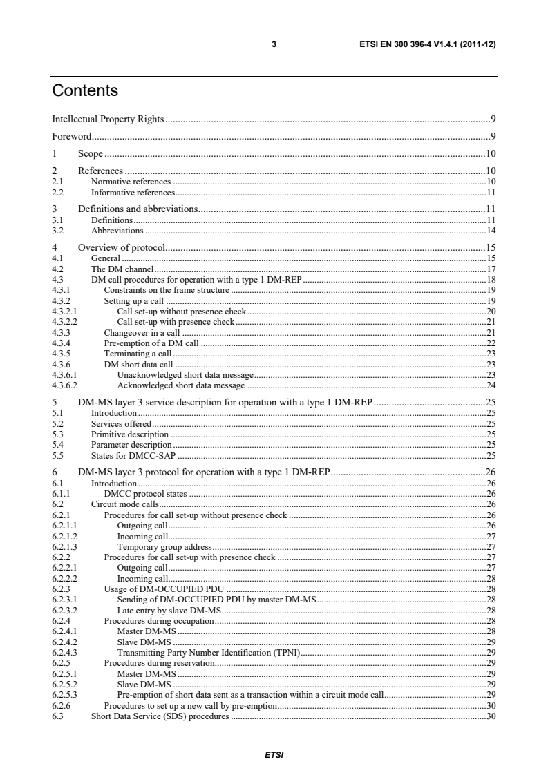
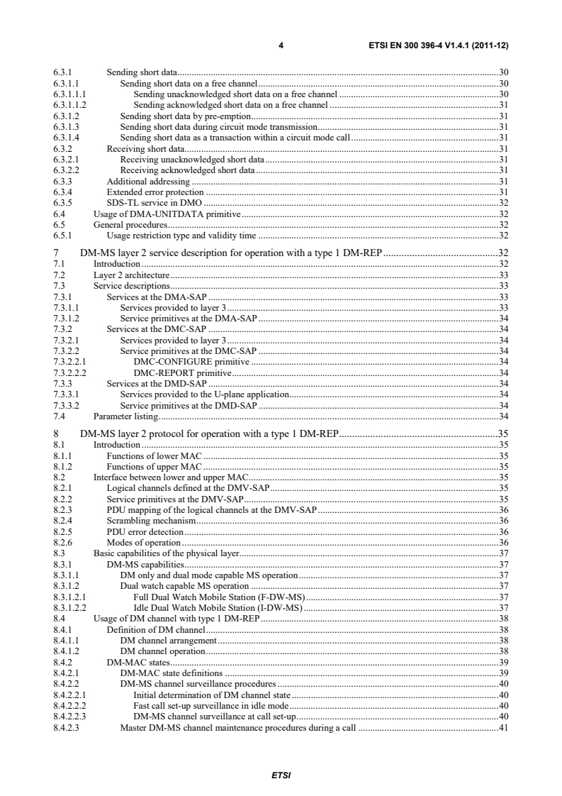
en_30039604v010401p - Terrestrial Trunked Radio (TETRA); Technical requirements for Direct Mode Operation (DMO); Part 4: Type 1 repeater air interface



SIST EN 300 396-4 V1.4.1:2012 is the SIST adoption of ETSI EN 300 396-4 V1.4.1 for Terrestrial Trunked Radio (TETRA) Direct Mode Operation (DMO). It specifies the Type 1 repeater air interface, including the physical layer, Data Link Layer (DLL) and network-layer procedures used when a Direct Mode Mobile Station (DM-MS) works through a Direct Mode REPeater (DM-REP). It is written for people implementing, integrating, testing or buying TETRA DMO equipment that must operate with a repeater.
What does SIST EN 300 396-4 V1.4.1:2012 specify?
SIST EN 300 396-4 V1.4.1:2012 covers a stand-alone type 1 DM-REP that supports a single call on the air interface, and the DM-MS procedures needed to work with it. The document is organized around the protocol overview, DM-MS layer 3 service and protocol, DM-MS layer 2 service and protocol, DM-REP layer 2 protocol, and PDU descriptions.
| Annex | What it covers |
|---|---|
| Annex A | Timers and constants for DM-MS and DM-REP operation with a type 1 DM-REP |
| Annex B | SDS-TL use in DMO |
| Annex C | Change requests |
What are the key requirements of SIST EN 300 396-4 V1.4.1:2012?
The repeater model is limited to one call at a time
SIST EN 300 396-4 V1.4.1:2012 defines type 1 DM-REP as a single-call repeater, with type 1A using one RF carrier and type 1B using a duplex-spaced uplink/downlink pair. In practice, equipment has to be designed for normal-mode repeater behavior, not multi-call support.
Channel access depends on the DM channel state
The standard treats the DM channel as free, occupied or reserved. That matters because call setup, traffic, pre-emption and reservation behavior change with the state, so a DM-MS must first determine channel state before it transmits.
Call setup can be done with or without presence check
For group and individual calls, a DM-MS may set up a call without presence check, or it may use presence check for individual calls to confirm that the destination is available. This affects whether the caller waits for a connect response before starting traffic.
Changeover and pre-emption are built into the protocol
A call transaction can end and another DM-MS can take over by changeover. A priority user can also pre-empt an occupied channel. In practice, this is how the system supports urgent access and talker handover without leaving the repeater context.
Timing, burst use and link roles are tightly defined
The master link and slave link are time-offset, and the protocol assigns specific uses to synchronization bursts, normal bursts, occupation, reservation, traffic and pre-emption opportunities. This is the part that drives frame timing, slot use and transmitter synchronization.
DM-MS and DM-REP behavior includes surveillance, retransmission and access control
The DM-MS and DM-REP layer 2 procedures cover channel surveillance, random access, retransmission of signalling messages, fragmentation, fill-bit handling, encryption and timing change. Annex A also fixes the main timers and constants used for retries and timeouts.
The repeater presence signal carries operating parameters
The presence signal can indicate repeater address, MNI of DM-REP, validity time, usage restriction type (URT), maximum DM-MS power class, power control flag, dual watch synchronization information, DT254, and DN232/DN233 values. In practice, this is how a DM-MS learns whether it may use the repeater and how long that permission lasts.
What terms does SIST EN 300 396-4 V1.4.1:2012 define?
- Direct Mode Operation (DMO) - Simplex operation where mobile radio units communicate outside control of the TETRA TMO network.
- Direct Mode REPeater (DM-REP) - A repeater that extends DMO coverage by retransmitting between DM-MSs.
- Direct Mode Mobile Station (DM-MS) - A mobile station used for TETRA DM services, acting as master, slave or idle depending on the call state.
- Direct Mode Call Control (DMCC) - The layer 3 entity that sets up and maintains a DMO call.
- DM channel - The timeslot grouping on a DM RF carrier, or carrier pair, used for a particular direct-mode communication.
- Pre-emption - The transfer of master role to a requesting DM-MS so it can take over the channel.
Who uses SIST EN 300 396-4 V1.4.1:2012?
SIST EN 300 396-4 V1.4.1:2012 is used by TETRA radio equipment designers, repeater vendors, mobile station developers, test laboratories, and system integrators. It also matters to operators and buyers planning DMO coverage, because it defines how repeaters, channel access, timing and call control behave in practice.
Which standards are used with SIST EN 300 396-4 V1.4.1:2012?
| Standard | What it contributes |
|---|---|
| ETSI EN 300 396-1 | General network design for TETRA DMO |
| ETSI EN 300 396-2 | Radio aspects and shared DMO framing/procedures |
| ETSI EN 300 396-3 | Base MS-MS air interface protocol used as the delta reference |
| ETSI EN 300 392-2 | TETRA Voice plus Data (V+D) air interface |
| ETSI EN 300 396-5 | Gateway air interface |
| ETSI EN 300 396-6 | Security for TETRA DMO |
| ETSI EN 300 396-7 | Type 2 repeater air interface, referenced for contrast and related operation |
What does the SIST EN 300 396-4 V1.4.1:2012 document contain?
SIST EN 300 396-4 V1.4.1:2012 contains protocol overviews, call-sequence descriptions, state-based MAC procedures, and detailed PDU and information-element coding. Clause 4 includes the call setup, changeover and pre-emption scenarios, while clauses 8 to 10 cover channel surveillance, retransmission, traffic mode behavior and PDU contents. The document also provides the tables that define timers, constants, frame counts, addressing formats, URT coding, repeater flags and related control values used for implementation and testing.
Buy Documents
en_30039604v010400o - Terrestrial Trunked Radio (TETRA); Technical requirements for Direct Mode Operation (DMO); Part 4: Type 1 repeater air interface
en_30039604v010401p - Terrestrial Trunked Radio (TETRA); Technical requirements for Direct Mode Operation (DMO); Part 4: Type 1 repeater air interface
Get Certified
Connect with accredited certification bodies for this standard

ANCE
Mexican certification and testing association.

Intertek Slovenia
Intertek testing, inspection, and certification services in Slovenia.

LNE (Laboratoire National de Métrologie et d'Essais)
French national laboratory for metrology and testing.
Sponsored listings
Frequently Asked Questions
SIST EN 300 396-4 V1.4.1:2012 is a standard published by the Slovenian Institute for Standardization (SIST). Its full title is "Terrestrial Trunked Radio (TETRA) - Technical requirements for Direct Mode Operation (DMO) - Part 4: Type 1 repeater air interface". This standard covers: REN/TETRA-08194
REN/TETRA-08194
SIST EN 300 396-4 V1.4.1:2012 is classified under the following ICS (International Classification for Standards) categories: 33.070.10 - Terrestrial Trunked Radio (TETRA). The ICS classification helps identify the subject area and facilitates finding related standards.
SIST EN 300 396-4 V1.4.1:2012 is associated with the following European legislation: Standardization Mandates: BC-T-344. When a standard is cited in the Official Journal of the European Union, products manufactured in conformity with it benefit from a presumption of conformity with the essential requirements of the corresponding EU directive or regulation.
SIST EN 300 396-4 V1.4.1:2012 is available in PDF format for immediate download after purchase. The document can be added to your cart and obtained through the secure checkout process. Digital delivery ensures instant access to the complete standard document.
Standards Content (Sample)
Final draft ETSI EN 300 396-4 V1.4.0 (2011-08)
European Standard
Terrestrial Trunked Radio (TETRA);
Technical requirements for Direct Mode Operation (DMO);
Part 4: Type 1 repeater air interface
2 Final draft ETSI EN 300 396-4 V1.4.0 (2011-08)
Reference
REN/TETRA-08194
Keywords
TETRA, DMO, repeater, protocol, radio, air
interface
ETSI
650 Route des Lucioles
F-06921 Sophia Antipolis Cedex - FRANCE
Tel.: +33 4 92 94 42 00 Fax: +33 4 93 65 47 16
Siret N° 348 623 562 00017 - NAF 742 C
Association à but non lucratif enregistrée à la
Sous-Préfecture de Grasse (06) N° 7803/88
Important notice
Individual copies of the present document can be downloaded from:
http://www.etsi.org
The present document may be made available in more than one electronic version or in print. In any case of existing or
perceived difference in contents between such versions, the reference version is the Portable Document Format (PDF).
In case of dispute, the reference shall be the printing on ETSI printers of the PDF version kept on a specific network drive
within ETSI Secretariat.
Users of the present document should be aware that the document may be subject to revision or change of status.
Information on the current status of this and other ETSI documents is available at
http://portal.etsi.org/tb/status/status.asp
If you find errors in the present document, please send your comment to one of the following services:
http://portal.etsi.org/chaircor/ETSI_support.asp
Copyright Notification
No part may be reproduced except as authorized by written permission.
The copyright and the foregoing restriction extend to reproduction in all media.
© European Telecommunications Standards Institute 2011.
All rights reserved.
TM TM TM
DECT , PLUGTESTS , UMTS and the ETSI logo are Trade Marks of ETSI registered for the benefit of its Members.
TM
3GPP and LTE™ are Trade Marks of ETSI registered for the benefit of its Members and
of the 3GPP Organizational Partners.
GSM® and the GSM logo are Trade Marks registered and owned by the GSM Association.
ETSI
3 Final draft ETSI EN 300 396-4 V1.4.0 (2011-08)
Contents
Intellectual Property Rights . 9
Foreword . 9
1 Scope . 10
2 References . 10
2.1 Normative references . 10
2.2 Informative references . 11
3 Definitions and abbreviations . 11
3.1 Definitions . 11
3.2 Abbreviations . 14
4 Overview of protocol. . 15
4.1 General . 15
4.2 The DM channel . 17
4.3 DM call procedures for operation with a type 1 DM-REP . 18
4.3.1 Constraints on the frame structure . 19
4.3.2 Setting up a call . 19
4.3.2.1 Call set-up without presence check . 20
4.3.2.2 Call set-up with presence check . 21
4.3.3 Changeover in a call . 21
4.3.4 Pre-emption of a DM call . 22
4.3.5 Terminating a call . 23
4.3.6 DM short data call . 23
4.3.6.1 Unacknowledged short data message . 23
4.3.6.2 Acknowledged short data message . 24
5 DM-MS layer 3 service description for operation with a type 1 DM-REP . 25
5.1 Introduction . 25
5.2 Services offered . 25
5.3 Primitive description . 25
5.4 Parameter description . 25
5.5 States for DMCC-SAP . 25
6 DM-MS layer 3 protocol for operation with a type 1 DM-REP . 26
6.1 Introduction . 26
6.1.1 DMCC protocol states . 26
6.2 Circuit mode calls . 26
6.2.1 Procedures for call set-up without presence check . 26
6.2.1.1 Outgoing call . 26
6.2.1.2 Incoming call. 27
6.2.1.3 Temporary group address . 27
6.2.2 Procedures for call set-up with presence check . 27
6.2.2.1 Outgoing call . 27
6.2.2.2 Incoming call. 28
6.2.3 Usage of DM-OCCUPIED PDU . 28
6.2.3.1 Sending of DM-OCCUPIED PDU by master DM-MS . 28
6.2.3.2 Late entry by slave DM-MS . 28
6.2.4 Procedures during occupation . 28
6.2.4.1 Master DM-MS . 28
6.2.4.2 Slave DM-MS . 29
6.2.4.3 Transmitting Party Number Identification (TPNI) . 29
6.2.5 Procedures during reservation. 29
6.2.5.1 Master DM-MS . 29
6.2.5.2 Slave DM-MS . 29
6.2.5.3 Pre-emption of short data sent as a transaction within a circuit mode call . 29
6.2.6 Procedures to set up a new call by pre-emption . 30
6.3 Short Data Service (SDS) procedures . 30
ETSI
4 Final draft ETSI EN 300 396-4 V1.4.0 (2011-08)
6.3.1 Sending short data . 30
6.3.1.1 Sending short data on a free channel . 30
6.3.1.1.1 Sending unacknowledged short data on a free channel . 30
6.3.1.1.2 Sending acknowledged short data on a free channel . 31
6.3.1.2 Sending short data by pre-emption . 31
6.3.1.3 Sending short data during circuit mode transmission . 31
6.3.1.4 Sending short data as a transaction within a circuit mode call . 31
6.3.2 Receiving short data. 31
6.3.2.1 Receiving unacknowledged short data . 31
6.3.2.2 Receiving acknowledged short data . 31
6.3.3 Additional addressing . 31
6.3.4 Extended error protection . 31
6.3.5 SDS-TL service in DMO . 32
6.4 Usage of DMA-UNITDATA primitive . 32
6.5 General procedures . 32
6.5.1 Usage restriction type and validity time . 32
7 DM-MS layer 2 service description for operation with a type 1 DM-REP . 32
7.1 Introduction . 32
7.2 Layer 2 architecture . 33
7.3 Service descriptions . 33
7.3.1 Services at the DMA-SAP . 33
7.3.1.1 Services provided to layer 3 . 33
7.3.1.2 Service primitives at the DMA-SAP . 34
7.3.2 Services at the DMC-SAP . 34
7.3.2.1 Services provided to layer 3 . 34
7.3.2.2 Service primitives at the DMC-SAP . 34
7.3.2.2.1 DMC-CONFIGURE primitive . 34
7.3.2.2.2 DMC-REPORT primitive . 34
7.3.3 Services at the DMD-SAP . 34
7.3.3.1 Services provided to the U-plane application . 34
7.3.3.2 Service primitives at the DMD-SAP . 34
7.4 Parameter listing . 34
8 DM-MS layer 2 protocol for operation with a type 1 DM-REP . 35
8.1 Introduction . 35
8.1.1 Functions of lower MAC . 35
8.1.2 Functions of upper MAC . 35
8.2 Interface between lower and upper MAC . 35
8.2.1 Logical channels defined at the DMV-SAP . 35
8.2.2 Service primitives at the DMV-SAP . 35
8.2.3 PDU mapping of the logical channels at the DMV-SAP . 36
8.2.4 Scrambling mechanism . 36
8.2.5 PDU error detection . 36
8.2.6 Modes of operation . 36
8.3 Basic capabilities of the physical layer. 37
8.3.1 DM-MS capabilitie s . 37
8.3.1.1 DM only and dual mode capable MS operation . 37
8.3.1.2 Dual watch capable MS operation . 37
8.3.1.2.1 Full Dual Watch Mobile Station (F-DW-MS) . 37
8.3.1.2.2 Idle Dual Watch Mobile Station (I-DW-MS) . 37
8.4 Usage of DM channel with type 1 DM-REP . 38
8.4.1 Definition of DM channel . 38
8.4.1.1 DM channel arrangement . 38
8.4.1.2 DM channel operation . 38
8.4.2 DM-MAC states . 39
8.4.2.1 DM-MAC state definitions . 39
8.4.2.2 DM-MS channel surveillance procedures . 40
8.4.2.2.1 Initial determination of DM channel state . 40
8.4.2.2.2 Fast call set-up surveillance in idle mode . 40
8.4.2.2.3 DM-MS channel surveillance at call set-up . 40
8.4.2.3 Master DM-MS channel maintenance procedures during a call . 41
ETSI
5 Final draft ETSI EN 300 396-4 V1.4.0 (2011-08)
8.4.2.4 Slave DM-MS channel maintenance procedures during a call . 41
8.4.2.4.1 Slave MS channel maintenance during call transaction . 41
8.4.2.4.2 Slave MS signal quality measurement during call transaction . 41
8.4.2.4.3 Slave MS channel maintenance during reservation . 42
8.4.3 Criteria for changing DM-MAC state . 42
8.4.3.1 Criteria for changing DM-MAC state for master DM-MS . 42
8.4.3.2 Criteria for changing DM-MAC state for slave DM-MS . 42
8.4.3.3 Criteria for changing DM-MAC state for idle DM-MS . 42
8.4.4 DM-MS channel monitoring procedures . 42
8.4.4.1 DM channel during initial call set-up and new call transaction by current master MS . 43
8.4.4.2 DM channel during call set-up with presence check . 43
8.4.4.3 DM channel in occupation during a circuit mode call. 43
8.4.4.4 DM channel in reservation during a circuit mode call . 43
8.4.4.5 DM channel in occupation during an SDS call . 44
8.4.4.6 DM channel usage during pre-emption signalling . 44
8.4.4.7 DM channel usage during timing change request signalling . 44
8.4.5 Transmission of layer 3 messages by DM-MAC . 44
8.4.5.1 Transmission of C-plane messages by DM-MAC. 44
8.4.5.2 Transmission of U-plane messages by DM-MAC . 45
8.4.6 Transmission of layer 2 messages generated by DM-MAC . 45
8.4.7 General DM-MAC procedures . 45
8.4.7.1 DM-MAC repeat transmissions . 45
8.4.7.2 DM-MAC frame countdown procedure . 45
8.4.7.3 Use of timers . 45
8.4.7.4 Linearization . 46
8.4.7.5 Fragmentation . 46
8.4.7.6 Fill bit indication . 47
8.4.7.7 Selection of pseudo address . 47
8.4.7.8 Slot flag indication . 47
8.4.7.9 Requests bitmap . 47
8.4.7.10 DM aspects of dual watch operation . 47
8.4.7.10.1 Full and idle dual watch operation. 47
8.4.7.10.2 DM aspects of full dual watch operation . 47
8.4.7.10.3 DM aspects of idle dual watch operation . 48
8.4.7.11 Air interface encryption . 48
8.4.7.12 Channel A or B operation . 48
8.4.7.13 Sending short data as a transaction within a circuit mode call . 48
8.4.7.14 SDS time remaining . 49
8.4.7.15 Timing change procedure . 49
8.4.7.16 Timing change at changeover or pre-emption . 49
8.5 MAC procedures for transfer of signalling messages . 49
8.5.1 Formation of MAC PDU . 49
8.5.2 Addressing . 49
8.5.2.1 Transmission of message . 50
8.5.2.1.1 Addressing in synchronization burst . 50
8.5.2.1.2 Addressing in normal burst. 50
8.5.2.2 Reception of message . 50
8.5.3 Use of air interface encryption . 51
8.5.4 Fragmentation and reconstruction . 51
8.5.4.1 Fragmentation . 51
8.5.4.2 Reconstruction . 52
8.5.5 Fill bit addition and deletion . 53
8.5.6 Transmission and reception of messages by layer 2 . 53
8.5.6.1 Transmission of message . 54
8.5.6.2 Reception of message . 54
8.5.7 Random access protocol . 56
8.5.7.1 Introduction . 56
8.5.7.2 Procedures for master DM-MS . 56
8.5.7.2.1 Indicating frames available for requests . 56
8.5.7.2.2 Monitoring frames available for requests . 56
8.5.7.2.3 Response to pre-emption or changeover request . 57
8.5.7.2.4 Response to timing change request. 57
ETSI
6 Final draft ETSI EN 300 396-4 V1.4.0 (2011-08)
8.5.7.3 Procedures for requesting DM-MS . 57
8.5.7.3.1 Preparing for random access . 58
8.5.7.3.2 First transmission of request . 58
8.5.7.3.3 Valid access slots . 58
8.5.7.3.4 Waiting for response . 58
8.5.7.3.5 Subsequent transmission of request . 59
8.5.7.3.6 Abandoning random access attempt . 59
8.6 MAC procedures in traffic mode . 59
8.6.1 Introduction. 59
8.6.2 Criteria for transmission and reception of traffic . 59
8.6.3 Change of U-plane mode . 60
8.6.3.1 Call set-up without presence check . 60
8.6.3.1.1 Outgoing call . 60
8.6.3.1.2 Incoming call . 60
8.6.3.2 Call set-up with presence check . 60
8.6.3.2.1 Outgoing call . 60
8.6.3.2.2 Incoming call . 61
8.6.3.3 Late entry . 61
8.6.3.4 End of traffic transmission . 61
8.6.3.4.1 Master DM-MS . 61
8.6.3.4.2 Slave DM-MS . 61
8.6.4 Exchange of information at the DMD-SAP . 61
8.6.5 Stealing from circuit mode capacity . 61
9 DM-REP layer 2 protocol for a type 1 DM-REP . 61
9.1 Introduction . 61
9.1.1 Functions of lower MAC . 62
9.1.2 Functions of upper MAC . 62
9.2 Interface between lower and upper MAC . 62
9.3 Basic capabilities of the DM-REP physical layer . 63
9.4 Usage of DM channel . 63
9.4.1 DM-REP operation . 63
9.4.1.1 Channel structure . 63
9.4.1.2 Channel synchronization . 63
9.4.2 DM-REP states . 64
9.4.2.1 DM-REP state definitions . 64
9.4.2.2 DM-REP channel surveillance procedures . 65
9.4.2.2.1 DM-REP channel surveillance when idle on a channel in unknown or free state (i.e. in state 0
or 1) . 65
9.4.2.2.2 DM-REP channel surveillance when idle on a busy channel (i.e. in state 2). 65
9.4.2.2.3 DM-REP channel surveillance when idle at DM-MS call set-up . 66
9.4.2.3 DM-REP channel maintenance when active during a call . 66
9.4.3 Criteria for changing DM-REP state . 67
9.4.3.1 Criteria for changing DM-REP state for active DM-REP . 67
9.4.3.2 Criteria for changing DM-REP state for idle DM-REP . 67
9.4.4 DM-REP channel monitoring procedures . 68
9.4.4.1 DM channel during call set-up with presence check . 69
9.4.4.2 DM channel in occupation during a circuit mode call. 69
9.4.4.3 DM channel in reservation during a circuit mode call . 69
9.4.4.4 DM channel in occupation during an SDS call . 70
9.4.4.5 DM channel following pre-emption or changeover acceptance . 70
9.4.4.6 DM channel following timing change announcement . 71
9.4.5 DM-REP presence signal . 71
9.4.5.1 Channel free . 71
9.4.5.2 Channel in occupation . 72
9.4.5.3 Channel in reservation . 72
9.4.6 DM-REP linearization . 73
9.5 DM-REP procedures for re-transmission of signalling messages . 73
9.5.1 Re-transmission of signalling messages received from the master DM-MS . 74
9.5.1.1 Re-transmission of master DM-MS signalling messages received in a DSB . 74
9.5.1.1.1 General procedures . 74
9.5.1.1.2 Re-transmission of DM-SETUP or DM-SETUP PRES message . 75
ETSI
7 Final draft ETSI EN 300 396-4 V1.4.0 (2011-08)
9.5.1.1.3 Re-transmission of DM-SDS DATA or DM-SDS UDATA message . 75
9.5.1.1.4 Re-transmission of other messages in a DSB when not using multi-slot regeneration . 76
9.5.1.1.5 Re-transmission of other messages in a DSB during traffic transmission with multi-slot
regeneration . 76
9.5.1.2 Re-transmission of master DM-MS signalling messages received in a DNB . 77
9.5.1.2.1 Call transaction without multi-slot regeneration . 77
9.5.1.2.2 Call transaction with multi-slot regeneration . 77
9.5.1.3 Regeneration of missing repetitions on the slave link . 78
9.5.2 Re-transmission of signalling messages received from a slave DM-MS . 78
9.5.2.1 General procedures. 78
9.5.2.2 Re-transmission of response messages from a slave DM-MS. 79
9.5.2.3 Re-transmission of random access request . 79
9.5.3 DM-REP signalling mechanisms . 80
9.5.3.1 Frame countdown procedure . 80
9.5.3.2 Fill bit addition and deletion . 80
9.5.3.3 Null PDU . 80
9.5.3.4 Air interface encryption . 80
9.5.3.5 Timing change procedure . 81
9.5.3.6 Random access procedures for DM-REP . 81
9.6 DM-REP procedures in traffic mode . 81
9.6.1 Introduction. 81
9.6.2 Change of U-plane mode . 81
9.6.2.1 Set-up without presence check . 81
9.6.2.1.1 Switching into traffic mode . 81
9.6.2.1.2 Link establishment failure . 82
9.6.2.2 Set-up with presence check . 82
9.6.2.3 End of traffic transmission . 82
9.6.3 DM-REP traffic operation when active in traffic mode . 83
9.6.3.1 Reception of TCH and STCH on the master link . 83
9.6.3.2 Re-transmission of TCH and STCH on the slave link. 83
9.6.3.2.1 Call transaction without multi-slot regeneration . 84
9.6.3.2.2 Call transaction with multi-slot regeneration . 84
10 PDU descriptions . 85
10.1 Layer 2 PDUs sent in DSB . 85
10.1.1 DMAC-SYNC PDU . 85
10.1.2 DPRES-SYNC PDU . 86
10.2 Layer 2 PDUs sent in DNB . 87
10.3 Layer 2 information element coding . 87
10.3.1 Addressing for URT = 0010 or 1000 . 88
2 2
10.3.2 Addressing for URT = 0011 or 1001 . 88
2 2
10.3.3 Addressing for URT = 0100 or 0101 . 88
2 2
10.3.4 Addressing for URT = 0110 . 88
10.3.4A Addressing for URT = 1010 . 88
10.3.4B Addressing for URT = 1011 . 89
10.3.5
...
European Standard
Terrestrial Trunked Radio (TETRA);
Technical requirements for Direct Mode Operation (DMO);
Part 4: Type 1 repeater air interface
2 ETSI EN 300 396-4 V1.4.1 (2011-12)
Reference
REN/TETRA-08194
Keywords
TETRA, DMO, repeater, protocol, radio, air
interface
ETSI
650 Route des Lucioles
F-06921 Sophia Antipolis Cedex - FRANCE
Tel.: +33 4 92 94 42 00 Fax: +33 4 93 65 47 16
Siret N° 348 623 562 00017 - NAF 742 C
Association à but non lucratif enregistrée à la
Sous-Préfecture de Grasse (06) N° 7803/88
Important notice
Individual copies of the present document can be downloaded from:
http://www.etsi.org
The present document may be made available in more than one electronic version or in print. In any case of existing or
perceived difference in contents between such versions, the reference version is the Portable Document Format (PDF).
In case of dispute, the reference shall be the printing on ETSI printers of the PDF version kept on a specific network drive
within ETSI Secretariat.
Users of the present document should be aware that the document may be subject to revision or change of status.
Information on the current status of this and other ETSI documents is available at
http://portal.etsi.org/tb/status/status.asp
If you find errors in the present document, please send your comment to one of the following services:
http://portal.etsi.org/chaircor/ETSI_support.asp
Copyright Notification
No part may be reproduced except as authorized by written permission.
The copyright and the foregoing restriction extend to reproduction in all media.
© European Telecommunications Standards Institute 2011.
All rights reserved.
TM TM TM
DECT , PLUGTESTS , UMTS and the ETSI logo are Trade Marks of ETSI registered for the benefit of its Members.
TM
3GPP and LTE™ are Trade Marks of ETSI registered for the benefit of its Members and
of the 3GPP Organizational Partners.
GSM® and the GSM logo are Trade Marks registered and owned by the GSM Association.
ETSI
3 ETSI EN 300 396-4 V1.4.1 (2011-12)
Contents
Intellectual Property Rights . 9
Foreword . 9
1 Scope . 10
2 References . 10
2.1 Normative references . 10
2.2 Informative references . 11
3 Definitions and abbreviations . 11
3.1 Definitions . 11
3.2 Abbreviations . 14
4 Overview of protocol. . 15
4.1 General . 15
4.2 The DM channel . 17
4.3 DM call procedures for operation with a type 1 DM-REP . 18
4.3.1 Constraints on the frame structure . 19
4.3.2 Setting up a call . 19
4.3.2.1 Call set-up without presence check . 20
4.3.2.2 Call set-up with presence check . 21
4.3.3 Changeover in a call . 21
4.3.4 Pre-emption of a DM call . 22
4.3.5 Terminating a call . 23
4.3.6 DM short data call . 23
4.3.6.1 Unacknowledged short data message . 23
4.3.6.2 Acknowledged short data message . 24
5 DM-MS layer 3 service description for operation with a type 1 DM-REP . 25
5.1 Introduction . 25
5.2 Services offered . 25
5.3 Primitive description . 25
5.4 Parameter description . 25
5.5 States for DMCC-SAP . 25
6 DM-MS layer 3 protocol for operation with a type 1 DM-REP . 26
6.1 Introduction . 26
6.1.1 DMCC protocol states . 26
6.2 Circuit mode calls . 26
6.2.1 Procedures for call set-up without presence check . 26
6.2.1.1 Outgoing call . 26
6.2.1.2 Incoming call. 27
6.2.1.3 Temporary group address . 27
6.2.2 Procedures for call set-up with presence check . 27
6.2.2.1 Outgoing call . 27
6.2.2.2 Incoming call. 28
6.2.3 Usage of DM-OCCUPIED PDU . 28
6.2.3.1 Sending of DM-OCCUPIED PDU by master DM-MS . 28
6.2.3.2 Late entry by slave DM-MS . 28
6.2.4 Procedures during occupation . 28
6.2.4.1 Master DM-MS . 28
6.2.4.2 Slave DM-MS . 29
6.2.4.3 Transmitting Party Number Identification (TPNI) . 29
6.2.5 Procedures during reservation. 29
6.2.5.1 Master DM-MS . 29
6.2.5.2 Slave DM-MS . 29
6.2.5.3 Pre-emption of short data sent as a transaction within a circuit mode call . 29
6.2.6 Procedures to set up a new call by pre-emption . 30
6.3 Short Data Service (SDS) procedures . 30
ETSI
4 ETSI EN 300 396-4 V1.4.1 (2011-12)
6.3.1 Sending short data . 30
6.3.1.1 Sending short data on a free channel . 30
6.3.1.1.1 Sending unacknowledged short data on a free channel . 30
6.3.1.1.2 Sending acknowledged short data on a free channel . 31
6.3.1.2 Sending short data by pre-emption . 31
6.3.1.3 Sending short data during circuit mode transmission . 31
6.3.1.4 Sending short data as a transaction within a circuit mode call . 31
6.3.2 Receiving short data. 31
6.3.2.1 Receiving unacknowledged short data . 31
6.3.2.2 Receiving acknowledged short data . 31
6.3.3 Additional addressing . 31
6.3.4 Extended error protection . 31
6.3.5 SDS-TL service in DMO . 32
6.4 Usage of DMA-UNITDATA primitive . 32
6.5 General procedures . 32
6.5.1 Usage restriction type and validity time . 32
7 DM-MS layer 2 service description for operation with a type 1 DM-REP . 32
7.1 Introduction . 32
7.2 Layer 2 architecture . 33
7.3 Service descriptions . 33
7.3.1 Services at the DMA-SAP . 33
7.3.1.1 Services provided to layer 3 . 33
7.3.1.2 Service primitives at the DMA-SAP . 34
7.3.2 Services at the DMC-SAP . 34
7.3.2.1 Services provided to layer 3 . 34
7.3.2.2 Service primitives at the DMC-SAP . 34
7.3.2.2.1 DMC-CONFIGURE primitive . 34
7.3.2.2.2 DMC-REPORT primitive . 34
7.3.3 Services at the DMD-SAP . 34
7.3.3.1 Services provided to the U-plane application . 34
7.3.3.2 Service primitives at the DMD-SAP . 34
7.4 Parameter listing . 34
8 DM-MS layer 2 protocol for operation with a type 1 DM-REP . 35
8.1 Introduction . 35
8.1.1 Functions of lower MAC . 35
8.1.2 Functions of upper MAC . 35
8.2 Interface between lower and upper MAC . 35
8.2.1 Logical channels defined at the DMV-SAP . 35
8.2.2 Service primitives at the DMV-SAP . 35
8.2.3 PDU mapping of the logical channels at the DMV-SAP . 36
8.2.4 Scrambling mechanism . 36
8.2.5 PDU error detection . 36
8.2.6 Modes of operation . 36
8.3 Basic capabilities of the physical layer. 37
8.3.1 DM-MS capabilitie s . 37
8.3.1.1 DM only and dual mode capable MS operation . 37
8.3.1.2 Dual watch capable MS operation . 37
8.3.1.2.1 Full Dual Watch Mobile Station (F-DW-MS) . 37
8.3.1.2.2 Idle Dual Watch Mobile Station (I-DW-MS) . 37
8.4 Usage of DM channel with type 1 DM-REP . 38
8.4.1 Definition of DM channel . 38
8.4.1.1 DM channel arrangement . 38
8.4.1.2 DM channel operation . 38
8.4.2 DM-MAC states . 39
8.4.2.1 DM-MAC state definitions . 39
8.4.2.2 DM-MS channel surveillance procedures . 40
8.4.2.2.1 Initial determination of DM channel state . 40
8.4.2.2.2 Fast call set-up surveillance in idle mode . 40
8.4.2.2.3 DM-MS channel surveillance at call set-up . 40
8.4.2.3 Master DM-MS channel maintenance procedures during a call . 41
ETSI
5 ETSI EN 300 396-4 V1.4.1 (2011-12)
8.4.2.4 Slave DM-MS channel maintenance procedures during a call . 41
8.4.2.4.1 Slave MS channel maintenance during call transaction . 41
8.4.2.4.2 Slave MS signal quality measurement during call transaction . 41
8.4.2.4.3 Slave MS channel maintenance during reservation . 42
8.4.3 Criteria for changing DM-MAC state . 42
8.4.3.1 Criteria for changing DM-MAC state for master DM-MS . 42
8.4.3.2 Criteria for changing DM-MAC state for slave DM-MS . 42
8.4.3.3 Criteria for changing DM-MAC state for idle DM-MS . 42
8.4.4 DM-MS channel monitoring procedures . 42
8.4.4.1 DM channel during initial call set-up and new call transaction by current master MS . 43
8.4.4.2 DM channel during call set-up with presence check . 43
8.4.4.3 DM channel in occupation during a circuit mode call. 43
8.4.4.4 DM channel in reservation during a circuit mode call . 43
8.4.4.5 DM channel in occupation during an SDS call . 44
8.4.4.6 DM channel usage during pre-emption signalling . 44
8.4.4.7 DM channel usage during timing change request signalling . 44
8.4.5 Transmission of layer 3 messages by DM-MAC . 44
8.4.5.1 Transmission of C-plane messages by DM-MAC. 44
8.4.5.2 Transmission of U-plane messages by DM-MAC . 45
8.4.6 Transmission of layer 2 messages generated by DM-MAC . 45
8.4.7 General DM-MAC procedures . 45
8.4.7.1 DM-MAC repeat transmissions . 45
8.4.7.2 DM-MAC frame countdown procedure . 45
8.4.7.3 Use of timers . 45
8.4.7.4 Linearization . 46
8.4.7.5 Fragmentation . 46
8.4.7.6 Fill bit indication . 47
8.4.7.7 Selection of pseudo address . 47
8.4.7.8 Slot flag indication . 47
8.4.7.9 Requests bitmap . 47
8.4.7.10 DM aspects of dual watch operation . 47
8.4.7.10.1 Full and idle dual watch operation. 47
8.4.7.10.2 DM aspects of full dual watch operation . 47
8.4.7.10.3 DM aspects of idle dual watch operation . 48
8.4.7.11 Air interface encryption . 48
8.4.7.12 Channel A or B operation . 48
8.4.7.13 Sending short data as a transaction within a circuit mode call . 48
8.4.7.14 SDS time remaining . 49
8.4.7.15 Timing change procedure . 49
8.4.7.16 Timing change at changeover or pre-emption . 49
8.5 MAC procedures for transfer of signalling messages . 49
8.5.1 Formation of MAC PDU . 49
8.5.2 Addressing . 49
8.5.2.1 Transmission of message . 50
8.5.2.1.1 Addressing in synchronization burst . 50
8.5.2.1.2 Addressing in normal burst. 50
8.5.2.2 Reception of message . 50
8.5.3 Use of air interface encryption . 51
8.5.4 Fragmentation and reconstruction . 51
8.5.4.1 Fragmentation . 51
8.5.4.2 Reconstruction . 52
8.5.5 Fill bit addition and deletion . 53
8.5.6 Transmission and reception of messages by layer 2 . 53
8.5.6.1 Transmission of message . 54
8.5.6.2 Reception of message . 54
8.5.7 Random access protocol . 56
8.5.7.1 Introduction . 56
8.5.7.2 Procedures for master DM-MS . 56
8.5.7.2.1 Indicating frames available for requests . 56
8.5.7.2.2 Monitoring frames available for requests . 57
8.5.7.2.3 Response to pre-emption or changeover request . 57
8.5.7.2.4 Response to timing change request. 57
ETSI
6 ETSI EN 300 396-4 V1.4.1 (2011-12)
8.5.7.3 Procedures for requesting DM-MS . 58
8.5.7.3.1 Preparing for random access . 58
8.5.7.3.2 First transmission of request . 58
8.5.7.3.3 Valid access slots . 58
8.5.7.3.4 Waiting for response . 59
8.5.7.3.5 Subsequent transmission of request . 59
8.5.7.3.6 Abandoning random access attempt . 59
8.6 MAC procedures in traffic mode . 59
8.6.1 Introduction. 59
8.6.2 Criteria for transmission and reception of traffic . 59
8.6.3 Change of U-plane mode . 60
8.6.3.1 Call set-up without presence check . 60
8.6.3.1.1 Outgoing call . 60
8.6.3.1.2 Incoming call . 60
8.6.3.2 Call set-up with presence check . 60
8.6.3.2.1 Outgoing call . 60
8.6.3.2.2 Incoming call . 61
8.6.3.3 Late entry . 61
8.6.3.4 End of traffic transmission . 61
8.6.3.4.1 Master DM-MS . 61
8.6.3.4.2 Slave DM-MS . 61
8.6.4 Exchange of information at the DMD-SAP . 61
8.6.5 Stealing from circuit mode capacity . 61
9 DM-REP layer 2 protocol for a type 1 DM-REP . 61
9.1 Introduction . 61
9.1.1 Functions of lower MAC . 62
9.1.2 Functions of upper MAC . 62
9.2 Interface between lower and upper MAC . 62
9.3 Basic capabilities of the DM-REP physical layer . 63
9.4 Usage of DM channel . 63
9.4.1 DM-REP operation . 63
9.4.1.1 Channel structure . 63
9.4.1.2 Channel synchronization . 64
9.4.2 DM-REP states . 64
9.4.2.1 DM-REP state definitions . 64
9.4.2.2 DM-REP channel surveillance procedures . 65
9.4.2.2.1 DM-REP channel surveillance when idle on a channel in unknown or free state (i.e. in state 0
or 1) . 65
9.4.2.2.2 DM-REP channel surveillance when idle on a busy channel (i.e. in state 2). 65
9.4.2.2.3 DM-REP channel surveillance when idle at DM-MS call set-up . 66
9.4.2.3 DM-REP channel maintenance when active during a call . 66
9.4.3 Criteria for changing DM-REP state . 67
9.4.3.1 Criteria for changing DM-REP state for active DM-REP . 67
9.4.3.2 Criteria for changing DM-REP state for idle DM-REP . 67
9.4.4 DM-REP channel monitoring procedures . 68
9.4.4.1 DM channel during call set-up with presence check . 69
9.4.4.2 DM channel in occupation during a circuit mode call. 69
9.4.4.3 DM channel in reservation during a circuit mode call . 69
9.4.4.4 DM channel in occupation during an SDS call . 70
9.4.4.5 DM channel following pre-emption or changeover acceptance . 70
9.4.4.6 DM channel following timing change announcement . 71
9.4.5 DM-REP presence signal . 71
9.4.5.1 Channel free . 71
9.4.5.2 Channel in occupation . 72
9.4.5.3 Channel in reservation . 73
9.4.6 DM-REP linearization . 73
9.5 DM-REP procedures for re-transmission of signalling messages . 74
9.5.1 Re-transmission of signalling messages received from the master DM-MS . 74
9.5.1.1 Re-transmission of master DM-MS signalling messages received in a DSB . 74
9.5.1.1.1 General procedures . 74
9.5.1.1.2 Re-transmission of DM-SETUP or DM-SETUP PRES message . 75
ETSI
7 ETSI EN 300 396-4 V1.4.1 (2011-12)
9.5.1.1.3 Re-transmission of DM-SDS DATA or DM-SDS UDATA message . 75
9.5.1.1.4 Re-transmission of other messages in a DSB when not using multi-slot regeneration . 76
9.5.1.1.5 Re-transmission of other messages in a DSB during traffic transmission with multi-slot
regeneration . 76
9.5.1.2 Re-transmission of master DM-MS signalling messages received in a DNB . 77
9.5.1.2.1 Call transaction without multi-slot regeneration . 77
9.5.1.2.2 Call transaction with multi-slot regeneration . 77
9.5.1.3 Regeneration of missing repetitions on the slave link . 78
9.5.2 Re-transmission of signalling messages received from a slave DM-MS . 78
9.5.2.1 General procedures. 78
9.5.2.2 Re-transmission of response messages from a slave DM-MS. 79
9.5.2.3 Re-transmission of random access request . 79
9.5.3 DM-REP signalling mechanisms . 80
9.5.3.1 Frame countdown procedure . 80
9.5.3.2 Fill bit addition and deletion . 80
9.5.3.3 Null PDU . 80
9.5.3.4 Air interface encryption . 80
9.5.3.5 Timing change procedure . 81
9.5.3.6 Random access procedures for DM-REP . 81
9.6 DM-REP procedures in traffic mode . 81
9.6.1 Introduction. 81
9.6.2 Change of U-plane mode . 82
9.6.2.1 Set-up without presence check . 82
9.6.2.1.1 Switching into traffic mode . 82
9.6.2.1.2 Link establishment failure . 82
9.6.2.2 Set-up with presence check . 82
9.6.2.3 End of traffic transmission . 83
9.6.3 DM-REP traffic operation when active in traffic mode . 83
9.6.3.1 Reception of TCH and STCH on the master link . 83
9.6.3.2 Re-transmission of TCH and STCH on the slave link. 84
9.6.3.2.1 Call transaction without multi-slot regeneration . 84
9.6.3.2.2 Call transaction with multi-slot regeneration . 84
10 PDU descriptions . 85
10.1 Layer 2 PDUs sent in DSB . 85
10.1.1 DMAC-SYNC PDU . 85
10.1.2 DPRES-SYNC PDU . 86
10.2 Layer 2 PDUs sent in DNB . 87
10.3 Layer 2 information element coding . 87
10.3.1 Addressing for URT = 0010 or 1000 . 88
2 2
10.3.2 Addressing for URT = 0011 or 1001 . 88
2 2
10.3.3 Addressing for URT = 0100 or 0101 . 88
2 2
10.3.4 Addressing for URT = 0110 . 88
10.3.4A Addressing for URT = 1010 . 88
10.3.4B Addressing for URT = 1011 . 89
10.3.5 Channel state .
...
2003-01.Slovenski inštitut za standardizacijo. Razmnoževanje celote ali delov tega standarda ni dovoljeno.QDþLQTerrestrial Trunked Radio (TETRA) - Technical requirements for Direct Mode Operation (DMO) - Part 4: Type 1 repeater air interface33.070.10Prizemni snopovni radio (TETRA)Terrestrial Trunked Radio (TETRA)ICS:Ta slovenski standard je istoveten z:EN 300 396-4 Version 1.4.1SIST EN 300 396-4 V1.4.1:2012en01-februar-2012SIST EN 300 396-4 V1.4.1:2012SLOVENSKI
STANDARD
European Standard SIST EN 300 396-4 V1.4.1:2012
ETSI ETSI EN 300 396-4 V1.4.1 (2011-12) 2
Reference REN/TETRA-08194 Keywords TETRA, DMO, repeater, protocol, radio, air interface ETSI 650 Route des Lucioles F-06921 Sophia Antipolis Cedex - FRANCE
Tel.: +33 4 92 94 42 00
Fax: +33 4 93 65 47 16
Siret N° 348 623 562 00017 - NAF 742 C Association à but non lucratif enregistrée à la Sous-Préfecture de Grasse (06) N° 7803/88
Important notice Individual copies of the present document can be downloaded from: http://www.etsi.org The present document may be made available in more than one electronic version or in print. In any case of existing or perceived difference in contents between such versions, the reference version is the Portable Document Format (PDF). In case of dispute, the reference shall be the printing on ETSI printers of the PDF version kept on a specific network drive within ETSI Secretariat. Users of the present document should be aware that the document may be subject to revision or change of status. Information on the current status of this and other ETSI documents is available at http://portal.etsi.org/tb/status/status.asp If you find errors in the present document, please send your comment to one of the following services: http://portal.etsi.org/chaircor/ETSI_support.asp Copyright Notification No part may be reproduced except as authorized by written permission. The copyright and the foregoing restriction extend to reproduction in all media.
© European Telecommunications Standards Institute 2011. All rights reserved.
DECTTM, PLUGTESTSTM, UMTSTM and the ETSI logo are Trade Marks of ETSI registered for the benefit of its Members. 3GPPTM and LTE™ are Trade Marks of ETSI registered for the benefit of its Members and of the 3GPP Organizational Partners. GSM® and the GSM logo are Trade Marks registered and owned by the GSM Association. SIST EN 300 396-4 V1.4.1:2012
ETSI ETSI EN 300 396-4 V1.4.1 (2011-12) 3 Contents Intellectual Property Rights . 9 Foreword . 9 1 Scope . 10 2 References . 10 2.1 Normative references . 10 2.2 Informative references . 11 3 Definitions and abbreviations . 11 3.1 Definitions . 11 3.2 Abbreviations . 14 4 Overview of protocol. 15 4.1 General . 15 4.2 The DM channel . 17 4.3 DM call procedures for operation with a type 1 DM-REP . 18 4.3.1 Constraints on the frame structure . 19 4.3.2 Setting up a call . 19 4.3.2.1 Call set-up without presence check . 20 4.3.2.2 Call set-up with presence check . 21 4.3.3 Changeover in a call . 21 4.3.4 Pre-emption of a DM call . 22 4.3.5 Terminating a call . 23 4.3.6 DM short data call . 23 4.3.6.1 Unacknowledged short data message . 23 4.3.6.2 Acknowledged short data message . 24 5 DM-MS layer 3 service description for operation with a type 1 DM-REP . 25 5.1 Introduction . 25 5.2 Services offered . 25 5.3 Primitive description . 25 5.4 Parameter description . 25 5.5 States for DMCC-SAP . 25 6 DM-MS layer 3 protocol for operation with a type 1 DM-REP . 26 6.1 Introduction . 26 6.1.1 DMCC protocol states . 26 6.2 Circuit mode calls . 26 6.2.1 Procedures for call set-up without presence check . 26 6.2.1.1 Outgoing call . 26 6.2.1.2 Incoming call. 27 6.2.1.3 Temporary group address . 27 6.2.2 Procedures for call set-up with presence check . 27 6.2.2.1 Outgoing call . 27 6.2.2.2 Incoming call. 28 6.2.3 Usage of DM-OCCUPIED PDU . 28 6.2.3.1 Sending of DM-OCCUPIED PDU by master DM-MS . 28 6.2.3.2 Late entry by slave DM-MS . 28 6.2.4 Procedures during occupation . 28 6.2.4.1 Master DM-MS . 28 6.2.4.2 Slave DM-MS . 29 6.2.4.3 Transmitting Party Number Identification (TPNI) . 29 6.2.5 Procedures during reservation. 29 6.2.5.1 Master DM-MS . 29 6.2.5.2 Slave DM-MS . 29 6.2.5.3 Pre-emption of short data sent as a transaction within a circuit mode call . 29 6.2.6 Procedures to set up a new call by pre-emption . 30 6.3 Short Data Service (SDS) procedures . 30 SIST EN 300 396-4 V1.4.1:2012
ETSI ETSI EN 300 396-4 V1.4.1 (2011-12) 4 6.3.1 Sending short data . 30 6.3.1.1 Sending short data on a free channel . 30 6.3.1.1.1 Sending unacknowledged short data on a free channel . 30 6.3.1.1.2 Sending acknowledged short data on a free channel . 31 6.3.1.2 Sending short data by pre-emption . 31 6.3.1.3 Sending short data during circuit mode transmission . 31 6.3.1.4 Sending short data as a transaction within a circuit mode call . 31 6.3.2 Receiving short data. 31 6.3.2.1 Receiving unacknowledged short data . 31 6.3.2.2 Receiving acknowledged short data . 31 6.3.3 Additional addressing . 31 6.3.4 Extended error protection . 31 6.3.5 SDS-TL service in DMO . 32 6.4 Usage of DMA-UNITDATA primitive . 32 6.5 General procedures . 32 6.5.1 Usage restriction type and validity time . 32 7 DM-MS layer 2 service description for operation with a type 1 DM-REP . 32 7.1 Introduction . 32 7.2 Layer 2 architecture . 33 7.3 Service descriptions . 33 7.3.1 Services at the DMA-SAP . 33 7.3.1.1 Services provided to layer 3 . 33 7.3.1.2 Service primitives at the DMA-SAP . 34 7.3.2 Services at the DMC-SAP . 34 7.3.2.1 Services provided to layer 3 . 34 7.3.2.2 Service primitives at the DMC-SAP . 34 7.3.2.2.1 DMC-CONFIGURE primitive . 34 7.3.2.2.2 DMC-REPORT primitive . 34 7.3.3 Services at the DMD-SAP . 34 7.3.3.1 Services provided to the U-plane application . 34 7.3.3.2 Service primitives at the DMD-SAP . 34 7.4 Parameter listing . 34 8 DM-MS layer 2 protocol for operation with a type 1 DM-REP . 35 8.1 Introduction . 35 8.1.1 Functions of lower MAC . 35 8.1.2 Functions of upper MAC . 35 8.2 Interface between lower and upper MAC . 35 8.2.1 Logical channels defined at the DMV-SAP . 35 8.2.2 Service primitives at the DMV-SAP . 35 8.2.3 PDU mapping of the logical channels at the DMV-SAP . 36 8.2.4 Scrambling mechanism . 36 8.2.5 PDU error detection . 36 8.2.6 Modes of operation . 36 8.3 Basic capabilities of the physical layer. 37 8.3.1 DM-MS capabilities . 37 8.3.1.1 DM only and dual mode capable MS operation . 37 8.3.1.2 Dual watch capable MS operation . 37 8.3.1.2.1 Full Dual Watch Mobile Station (F-DW-MS) . 37 8.3.1.2.2 Idle Dual Watch Mobile Station (I-DW-MS) . 37 8.4 Usage of DM channel with type 1 DM-REP . 38 8.4.1 Definition of DM channel . 38 8.4.1.1 DM channel arrangement . 38 8.4.1.2 DM channel operation . 38 8.4.2 DM-MAC states . 39 8.4.2.1 DM-MAC state definitions . 39 8.4.2.2 DM-MS channel surveillance procedures . 40 8.4.2.2.1 Initial determination of DM channel state . 40 8.4.2.2.2 Fast call set-up surveillance in idle mode . 40 8.4.2.2.3 DM-MS channel surveillance at call set-up . 40 8.4.2.3 Master DM-MS channel maintenance procedures during a call . 41 SIST EN 300 396-4 V1.4.1:2012
ETSI ETSI EN 300 396-4 V1.4.1 (2011-12) 5 8.4.2.4 Slave DM-MS channel maintenance procedures during a call . 41 8.4.2.4.1 Slave MS channel maintenance during call transaction . 41 8.4.2.4.2 Slave MS signal quality measurement during call transaction . 41 8.4.2.4.3 Slave MS channel maintenance during reservation . 42 8.4.3 Criteria for changing DM-MAC state . 42 8.4.3.1 Criteria for changing DM-MAC state for master DM-MS . 42 8.4.3.2 Criteria for changing DM-MAC state for slave DM-MS . 42 8.4.3.3 Criteria for changing DM-MAC state for idle DM-MS . 42 8.4.4 DM-MS channel monitoring procedures . 42 8.4.4.1 DM channel during initial call set-up and new call transaction by current master MS . 43 8.4.4.2 DM channel during call set-up with presence check . 43 8.4.4.3 DM channel in occupation during a circuit mode call. 43 8.4.4.4 DM channel in reservation during a circuit mode call . 43 8.4.4.5 DM channel in occupation during an SDS call . 44 8.4.4.6 DM channel usage during pre-emption signalling . 44 8.4.4.7 DM channel usage during timing change request signalling . 44 8.4.5 Transmission of layer 3 messages by DM-MAC . 44 8.4.5.1 Transmission of C-plane messages by DM-MAC. 44 8.4.5.2 Transmission of U-plane messages by DM-MAC . 45 8.4.6 Transmission of layer 2 messages generated by DM-MAC . 45 8.4.7 General DM-MAC procedures . 45 8.4.7.1 DM-MAC repeat transmissions . 45 8.4.7.2 DM-MAC frame countdown procedure . 45 8.4.7.3 Use of timers . 45 8.4.7.4 Linearization . 46 8.4.7.5 Fragmentation . 46 8.4.7.6 Fill bit indication . 47 8.4.7.7 Selection of pseudo address . 47 8.4.7.8 Slot flag indication . 47 8.4.7.9 Requests bitmap . 47 8.4.7.10 DM aspects of dual watch operation . 47 8.4.7.10.1 Full and idle dual watch operation. 47 8.4.7.10.2 DM aspects of full dual watch operation . 47 8.4.7.10.3 DM aspects of idle dual watch operation . 48 8.4.7.11 Air interface encryption . 48 8.4.7.12 Channel A or B operation . 48 8.4.7.13 Sending short data as a transaction within a circuit mode call . 48 8.4.7.14 SDS time remaining . 49 8.4.7.15 Timing change procedure . 49 8.4.7.16 Timing change at changeover or pre-emption . 49 8.5 MAC procedures for transfer of signalling messages . 49 8.5.1 Formation of MAC PDU . 49 8.5.2 Addressing . 49 8.5.2.1 Transmission of message . 50 8.5.2.1.1 Addressing in synchronization burst . 50 8.5.2.1.2 Addressing in normal burst. 50 8.5.2.2 Reception of message . 50 8.5.3 Use of air interface encryption . 51 8.5.4 Fragmentation and reconstruction . 51 8.5.4.1 Fragmentation . 51 8.5.4.2 Reconstruction . 52 8.5.5 Fill bit addition and deletion . 53 8.5.6 Transmission and reception of messages by layer 2 . 53 8.5.6.1 Transmission of message . 54 8.5.6.2 Reception of message . 54 8.5.7 Random access protocol . 56 8.5.7.1 Introduction . 56 8.5.7.2 Procedures for master DM-MS . 56 8.5.7.2.1 Indicating frames available for requests . 56 8.5.7.2.2 Monitoring frames available for requests . 57 8.5.7.2.3 Response to pre-emption or changeover request . 57 8.5.7.2.4 Response to timing change request. 57 SIST EN 300 396-4 V1.4.1:2012
ETSI ETSI EN 300 396-4 V1.4.1 (2011-12) 6 8.5.7.3 Procedures for requesting DM-MS . 58 8.5.7.3.1 Preparing for random access . 58 8.5.7.3.2 First transmission of request . 58 8.5.7.3.3 Valid access slots . 58 8.5.7.3.4 Waiting for response . 59 8.5.7.3.5 Subsequent transmission of request . 59 8.5.7.3.6 Abandoning random access attempt . 59 8.6 MAC procedures in traffic mode . 59 8.6.1 Introduction. 59 8.6.2 Criteria for transmission and reception of traffic . 59 8.6.3 Change of U-plane mode . 60 8.6.3.1 Call set-up without presence check . 60 8.6.3.1.1 Outgoing call . 60 8.6.3.1.2 Incoming call . 60 8.6.3.2 Call set-up with presence check . 60 8.6.3.2.1 Outgoing call . 60 8.6.3.2.2 Incoming call . 61 8.6.3.3 Late entry . 61 8.6.3.4 End of traffic transmission . 61 8.6.3.4.1 Master DM-MS . 61 8.6.3.4.2 Slave DM-MS . 61 8.6.4 Exchange of information at the DMD-SAP . 61 8.6.5 Stealing from circuit mode capacity . 61 9 DM-REP layer 2 protocol for a type 1 DM-REP . 61 9.1 Introduction . 61 9.1.1 Functions of lower MAC . 62 9.1.2 Functions of upper MAC . 62 9.2 Interface between lower and upper MAC . 62 9.3 Basic capabilities of the DM-REP physical layer . 63 9.4 Usage of DM channel . 63 9.4.1 DM-REP operation . 63 9.4.1.1 Channel structure . 63 9.4.1.2 Channel synchronization . 64 9.4.2 DM-REP states . 64 9.4.2.1 DM-REP state definitions . 64 9.4.2.2 DM-REP channel surveillance procedures . 65 9.4.2.2.1 DM-REP channel surveillance when idle on a channel in unknown or free state (i.e. in state 0 or 1) . 65 9.4.2.2.2 DM-REP channel surveillance when idle on a busy channel (i.e. in state 2). 65 9.4.2.2.3 DM-REP channel surveillance when idle at DM-MS call set-up . 66 9.4.2.3 DM-REP channel maintenance when active during a call . 66 9.4.3 Criteria for changing DM-REP state . 67 9.4.3.1 Criteria for changing DM-REP state for active DM-REP . 67 9.4.3.2 Criteria for changing DM-REP state for idle DM-REP . 67 9.4.4 DM-REP channel monitoring procedures . 68 9.4.4.1 DM channel during call set-up with presence check . 69 9.4.4.2 DM channel in occupation during a circuit mode call. 69 9.4.4.3 DM channel in reservation during a circuit mode call . 69 9.4.4.4 DM channel in occupation during an SDS call . 70 9.4.4.5 DM channel following pre-emption or changeover acceptance . 70 9.4.4.6 DM channel following timing change announcement . 71 9.4.5 DM-REP presence signal . 71 9.4.5.1 Channel free . 71 9.4.5.2 Channel in occupation . 72 9.4.5.3 Channel in reservation . 73 9.4.6 DM-REP linearization . 73 9.5 DM-REP procedures for re-transmission of signalling messages . 74 9.5.1 Re-transmission of signalling messages received from the master DM-MS . 74 9.5.1.1 Re-transmission of master DM-MS signalling messages received in a DSB . 74 9.5.1.1.1 General procedures . 74 9.5.1.1.2 Re-transmission of DM-SETUP or DM-SETUP PRES message . 75 SIST EN 300 396-4 V1.4.1:2012
ETSI ETSI EN 300 396-4 V1.4.1 (2011-12) 7 9.5.1.1.3 Re-transmission of DM-SDS DATA or DM-SDS UDATA message . 75 9.5.1.1.4 Re-transmission of other messages in a DSB when not using multi-slot regeneration . 76 9.5.1.1.5 Re-transmission of other messages in a DSB during traffic transmission with multi-slot regeneration . 76 9.5.1.2 Re-transmission of master DM-MS signalling messages received in a DNB . 77 9.5.1.2.1 Call transaction without multi-slot regeneration . 77 9.5.1.2.2 Call transaction with multi-slot regeneration . 77 9.5.1.3 Regeneration of missing repetitions on the slave link . 78 9.5.2 Re-transmission of signalling messages received from a slave DM-MS . 78 9.5.2.1 General procedures. 78 9.5.2.2 Re-transmission of response messages from a slave DM-MS. 79 9.5.2.3 Re-transmission of random access request . 79 9.5.3 DM-REP signalling mechanisms . 80 9.5.3.1 Frame countdown procedure . 80 9.5.3.2 Fill bit addition and deletion . 80 9.5.3.3 Null PDU . 80 9.5.3.4 Air interface encryption . 80 9.5.3.5 Timing change procedure . 81 9.5.3.6 Random access procedures for DM-REP . 81 9.6 DM-REP procedures in traffic mode . 81 9.6.1 Introduction. 81 9.6.2 Change of U-plane mode . 82 9.6.2.1 Set-up without presence check . 82 9.6.2.1.1 Switching into traffic mode . 82 9.6.2.1.2 Link establishment failure . 82 9.6.2.2 Set-up with presence check . 82 9.6.2.3 End of traffic transmission . 83 9.6.3 DM-REP traffic operation when active in traffic mode . 83 9.6.3.1 Reception of TCH and STCH on the master link . 83 9.6.3.2 Re-transmission of TCH and STCH on the slave link. 84 9.6.3.2.1 Call transaction without multi-slot regeneration . 84 9.6.3.2.2 Call transaction with multi-slot regeneration . 84 10 PDU descriptions . 85 10.1 Layer 2 PDUs sent in DSB . 85 10.1.1 DMAC-SYNC PDU . 85 10.1.2 DPRES-SYNC PDU . 86 10.2 Layer 2 PDUs sent in DNB . 87 10.3 Layer 2 information element coding . 87 10.3.1 Addressing for URT = 00102 or 10002 . 88 10.3.2 Addressing for URT = 00112 or 10012 . 88 10.3.3 Addressing for URT = 01002 or 01012 . 88 10.3.4 Addressing for URT = 01102 . 88 10.3.4A Addressing for URT = 10102 . 88 10.3.4B Addressing for URT = 10112 . 89 10.3.5 Channel state .
...