ISO/DIS 23475-1
Titre manque
General Information
Standards Content (sample)
DRAFT INTERNATIONAL STANDARD
ISO/DIS 23475-1
ISO/TC 17/SC 17 Secretariat: SAC
Voting begins on: Voting terminates on:
2020-03-23 2020-06-15
Testing method for steel tyre cord —
Part 1:
General requirements
ICS: 77.140.65; 83.160.01
THIS DOCUMENT IS A DRAFT CIRCULATED
FOR COMMENT AND APPROVAL. IT IS
THEREFORE SUBJECT TO CHANGE AND MAY
NOT BE REFERRED TO AS AN INTERNATIONAL
STANDARD UNTIL PUBLISHED AS SUCH.
IN ADDITION TO THEIR EVALUATION AS
BEING ACCEPTABLE FOR INDUSTRIAL,
This document is circulated as received from the committee secretariat.
TECHNOLOGICAL, COMMERCIAL AND
USER PURPOSES, DRAFT INTERNATIONAL
STANDARDS MAY ON OCCASION HAVE TO
BE CONSIDERED IN THE LIGHT OF THEIR
POTENTIAL TO BECOME STANDARDS TO
WHICH REFERENCE MAY BE MADE IN
Reference number
NATIONAL REGULATIONS.
ISO/DIS 23475-1:2020(E)
RECIPIENTS OF THIS DRAFT ARE INVITED
TO SUBMIT, WITH THEIR COMMENTS,
NOTIFICATION OF ANY RELEVANT PATENT
RIGHTS OF WHICH THEY ARE AWARE AND TO
PROVIDE SUPPORTING DOCUMENTATION. ISO 2020
---------------------- Page: 1 ----------------------
ISO/DIS 23475-1:2020(E)
COPYRIGHT PROTECTED DOCUMENT
© ISO 2020
All rights reserved. Unless otherwise specified, or required in the context of its implementation, no part of this publication may
be reproduced or utilized otherwise in any form or by any means, electronic or mechanical, including photocopying, or posting
on the internet or an intranet, without prior written permission. Permission can be requested from either ISO at the address
below or ISO’s member body in the country of the requester.ISO copyright office
CP 401 • Ch. de Blandonnet 8
CH-1214 Vernier, Geneva
Phone: +41 22 749 01 11
Fax: +41 22 749 09 47
Email: copyright@iso.org
Website: www.iso.org
Published in Switzerland
ii © ISO 2020 – All rights reserved
---------------------- Page: 2 ----------------------
ISO/DIS 23475-1:2020(E)
Contents Page
Foreword ..........................................................................................................................................................................................................................................v
1 Scope ................................................................................................................................................................................................................................. 1
2 Normative references ...................................................................................................................................................................................... 1
3 Terms and definitions ..................................................................................................................................................................................... 1
4 Dimension ................................................................................................................................................................................................................... 1
4.1 Cord diameter .......................................................................................................................................................................................... 1
4.1.1 Measure with micrometer ....................................................................................................................................... 1
4.1.2 Measure with profile projector ........................................................................................................................... 3
4.2 Unravelled Filament diameter ................................................................................................................................................... 4
4.2.1 Principle .................................................................................................................................................................................. 4
4.2.2 Apparatus ............................................................................................................................................................................... 5
4.2.3 Procedure ............................................................................................................................................................................... 5
4.2.4 Expression of results .................................................................................................................................................... 5
4.2.5 Test report ............................................................................................................................................................................. 5
4.3 Linear density .......................................................................................................................................................................................... 6
4.3.1 Principle .................................................................................................................................................................................. 6
4.3.2 Apparatus ............................................................................................................................................................................... 6
4.3.3 Procedure ............................................................................................................................................................................... 6
4.3.4 Test report ............................................................................................................................................................................. 6
4.4 Lay direction and lay length ........................................................................................................................................................ 6
4.4.1 Lay direction/direction of lay ............................................................................................................................... 6
4.4.2 Trace method for lay length ................................................................................................................................... 7
4.4.3 Untwisting method for lay length ..................................................................................................................... 8
5 Process property .................................................................................................................................................................................................. 9
5.1 Straightness ............................................................................................................................................................................................... 9
5.1.1 Principle .................................................................................................................................................................................. 9
5.1.2 Apparatus ............................................................................................................................................................................... 9
5.1.3 Procedure ............................................................................................................................................................................... 9
5.1.4 Test Report ............................................................................................................................................................................ 9
5.2 Arc height ..................................................................................................................................................................................................10
5.2.1 Principle ...............................................................................................................................................................................10
5.2.2 Apparatus ............................................................................................................................................................................10
5.2.3 Procedure ............................................................................................................................................................................10
5.2.4 Test report ..........................................................................................................................................................................10
5.3 Flare ...............................................................................................................................................................................................................10
5.3.1 Principle ...............................................................................................................................................................................10
5.3.2 Apparatus ............................................................................................................................................................................10
5.3.3 Procedure ............................................................................................................................................................................10
5.3.4 Test report ..........................................................................................................................................................................11
5.4 Residual torsion ..................................................................................................................................................................................11
5.4.1 Principle ...............................................................................................................................................................................11
5.4.2 Apparatus ............................................................................................................................................................................11
5.4.3 Procedure ............................................................................................................................................................................11
5.4.4 Test report ..........................................................................................................................................................................11
6 Mechanical property .....................................................................................................................................................................................12
6.1 Breaking load and elongation at fracture .....................................................................................................................12
6.1.1 Principle ...............................................................................................................................................................................12
6.1.2 Apparatus ............................................................................................................................................................................12
6.1.3 Procedure ............................................................................................................................................................................12
6.1.4 Test report ..........................................................................................................................................................................13
6.2 Elongation between defined forces (EDF) ...................................................................................................................13
6.2.1 Principle ...............................................................................................................................................................................13
© ISO 2020 – All rights reserved iii---------------------- Page: 3 ----------------------
ISO/DIS 23475-1:2020(E)
6.2.2 Apparatus ............................................................................................................................................................................14
6.2.3 Procedure ............................................................................................................................................................................14
6.2.4 Test report ..........................................................................................................................................................................15
6.3 Loop test (Elasticity) .......................................................................................................................................................................15
6.3.1 Principle ...............................................................................................................................................................................15
6.3.2 Apparatus ............................................................................................................................................................................15
6.3.3 Procedure ............................................................................................................................................................................16
6.3.4 Test report ..........................................................................................................................................................................17
7 Determination of mass and composition of coating .....................................................................................................17
7.1 X-Ray fluorescence spectroscopy .........................................................................................................................................17
7.1.1 Principle ...............................................................................................................................................................................17
7.1.2 Apparatus ............................................................................................................................................................................17
7.1.3 Reagents ...............................................................................................................................................................................17
7.1.4 Preparation of test samples .................................................................................................................................18
7.1.5 Procedure ............................................................................................................................................................................18
7.1.6 Expression of results .................................................................................................................................................18
7.1.7 Test report ..........................................................................................................................................................................19
iv © ISO 2020 – All rights reserved---------------------- Page: 4 ----------------------
ISO/DIS 23475-1:2020(E)
Foreword
ISO (the International Organization for Standardization) is a worldwide federation of national standards
bodies (ISO member bodies). The work of preparing International Standards is normally carried out
through ISO technical committees. Each member body interested in a subject for which a technical
committee has been established has the right to be represented on that committee. International
organizations, governmental and non-governmental, in liaison with ISO, also take part in the work.
ISO collaborates closely with the International Electrotechnical Commission (IEC) on all matters of
electrotechnical standardization.The procedures used to develop this document and those intended for its further maintenance are
described in the ISO/IEC Directives, Part 1. In particular, the different approval criteria needed for the
different types of ISO documents should be noted. This document was drafted in accordance with the
editorial rules of the ISO/IEC Directives, Part 2 (see www .iso .org/ directives).
Attention is drawn to the possibility that some of the elements of this document may be the subject of
patent rights. ISO shall not be held responsible for identifying any or all such patent rights. Details of
any patent rights identified during the development of the document will be in the Introduction and/or
on the ISO list of patent declarations received (see www .iso .org/ patents).Any trade name used in this document is information given for the convenience of users and does not
constitute an endorsement.For an explanation of the voluntary nature of standards, the meaning of ISO specific terms and
expressions related to conformity assessment, as well as information about ISO's adherence to the
World Trade Organization (WTO) principles in the Technical Barriers to Trade (TBT), see www .iso .org/
iso/ foreword .html.This document was prepared by Technical Committee ISO/TC17, Steel, Subcommittee SC 17, Steel wire
rod and wire products.A list of all parts in the ISO 23475 series can be found on the ISO website.
© ISO 2020 – All rights reserved v
---------------------- Page: 5 ----------------------
DRAFT INTERNATIONAL STANDARD ISO/DIS 23475-1:2020(E)
Testing method for steel tyre cord —
Part 1:
General requirements
1 Scope
This part of International standard specifies test methods of steel cords which are used for tyre
reinforcement. Dimension, process properties, mechanical properities and coating test method are all
included.2 Normative references
The following referenced documents are indispensable for the application of this document. For dated
references, only the edition cited applies. For undated references, the latest edition of the referenced
document (including any amendments) applies.ISO 17832, Non-parallel steel wire and cords for tyre reinforcement
3 Terms and definitions
For the purposes of this document, the terms and definitions given in ISO 17832 apply.
4 Dimension4.1 Cord diameter
4.1.1 Measure with micrometer
4.1.1.1 Principle
Hold the sample between two parallel circular faced anvils of a micrometer. Close the movable anvil
gradually and gently until it is in contact with the specimen. Read the value on the micrometer.
4.1.1.2 Apparatus4.1.1.2.1 Micrometer
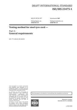
A precision disk micrometer with non-rotate spindle is suggested. This micrometer may have a hole
(maximum 8mm) in the center of the anvils.(Figure 1)Measuring range is from 0mm to 25mm.Resolution is 0,001mm
Anvil type: the dimeter of the anvils shall be greater than one lay length (min. 20 mm in diameter).
Measuring force range: <10 N. It is suggested from 3N-5 N.The anvils shall be plane within 0,002mm and parallel within 0,005mm.
© ISO 2020 – All rights reserved 1
---------------------- Page: 6 ----------------------
ISO/DIS 23475-1:2020(E)
Figure 1 — Disk micrometer
4.1.1.2.2 Fusing machine
4.1.1.3 Procedure
a) Clean the surface of the anvils with clean paper. Verify whether the micrometer reads 0,000 when
the anvils are closed for each measurement.b) Fuse a specimen to a length about 150 mm and take care that cord end is well secured and no
unraveling Place the sample in the center of the anvils.c) Close the movable anvil gradually and gently until it is in contact with the specimen. For normal
cords, stop rotating the spindle when 3 ‘click’ are heard and for HE, HI and OC constructions only 1
“click” is heard.d) Axially rotate the sample between repeated measurements in order to find the maximum diameter
(D ) and minimum diameter (D )1 2
Figure 2 — Diameter test diagram
4.1.1.4 Expression of results
Calculate average diameter (D) with the formula below:
DD+
D= (1)
where
2 © ISO 2020 – All rights reserved
---------------------- Page: 7 ----------------------
ISO/DIS 23475-1:2020(E)
D is the maximum diameter, expressed in millimetre (mm)
D is the minimum diameter, expressed in millimetre (mm)
D is the average diameter, expressed in millimetre (mm)
4.1.1.5 Test report
Report the average diameter to nearest 0,001mm
4.1.2 Measure with profile projector
4.1.2.1 Principle
Specimens of a cord sample are successively put on the optical microscope. A silhouette of the cord is
projected on the screen. The thickness of the specimen is measured by moving the abscissa axis of the
projector.4.1.2.2 Apparatus
4.1.2.2.1 Profile projector, with
— Magnification possibility : x 10 or x 20
— Micrometer stage table: resolution 0,001 mm
4.1.2.2.2 Sample holder, A frame on which two magnets are fixed in order to position the test
specimen4.1.2.2.3 Fusing machine
4.1.2.3 Procedure
a) Fuse a specimen to a length about 100mm, ensure that fuse is well done in order to prevent the
cord ends from any unravelling. Put the specimen on the sample holder and ensure that is fixed by
magnets.b) Bring the sample into sample holder and adjust the focal distance. Make the sample being projected
on the screen.c) Rotate the sample until the maximum profile is being projected on the screen. Move the micrometer
table until the horizontal reference line contacts two consecutive waves. (figure3).
Figure 3 — X axis contacts the two consecutive waves© ISO 2020 – All rights reserved 3
---------------------- Page: 8 ----------------------
ISO/DIS 23475-1:2020(E)
d) Reset the micrometer. Move the stage until X axis contacts the opposite wave (Figure 4). Record
the reading as maximum diameter (D . If there are two waves on the opposite side, measure the
bigger one.Figure 4 — X axis contacts the other side wave
e) Turn the specimen through 90 degrees until a minimum diameter is obtained, record the minimum
diameter D . Repeat the step c and d and record the reading as minimum diameter (D ). If there are
2 2two waves on the opposite side, measures the bigger one (Figure 5).
Figure 5 — the minimum diameter
4.1.2.4 Expression of results
Calculate average diameter (D) of the two readings with formula (1).
4.1.2.5 Test Report
Report the average diameter to the nearest 0,001mm.
NOTE This test method is generally used for open cords and HI cords or for other cord types that are
sensitive to radial compression when using micrometer.4.2 Unravelled Filament diameter
4.2.1 Principle
A sample is held between two parallel blade anvils of a micrometer. The movable anvil is closed
gradually and gently until it is in contact with the specimen. Read the value on the micrometer.
4 © ISO 2020 – All rights reserved---------------------- Page: 9 ----------------------
ISO/DIS 23475-1:2020(E)
4.2.2 Apparatus
4.2.2.1 Blade micrometer (see Figure 6)
— Measuring range is from 0mm to 25 mm. Resolution is 0,001 mm.
— Anvil type: blade
— Measuring force: <10 N. It is suggested from 3N - 5 N.
Figure 6 — Blade micrometer
4.2.2.2 Nipper pliers
4.2.3 Procedure
a) Clean the surface of the anvils with clean paper. Verify whether the micrometer reads 0,000 when
the anvils are closed for each measurement.b) Cut the wire approximately 100 mm in length. Position the specimen in the center of the anvils.
c) The movable anvil is closed gradually and gently until it is in contact with the specimen. Read the
value after 3 ‘click’ are heard.d) Measure on the same section of the specimen until Max diameter (d ) and Min diameter (d ) is found.
1 24.2.4 Expression of results
Calculate average diameter (d) of the two readings with the formula below.
dd+
d = (2)
where
d : is the maximum diameter, expressed in millimetre (mm).
d : is the minimum diameter, expressed in millimetre (mm)
d: is average diameter, expressed in millimetre (mm).
4.2.5 Test report
Report the average diameter to the nearest 0,001mm.
© ISO 2020 – All rights reserved 5
---------------------- Page: 10 ----------------------
ISO/DIS 23475-1:2020(E)
4.3 Linear density
4.3.1 Principle
A straight section of the cord of a predefined length, generally 1 m, is weighted using an analytical
balance.4.3.2 Apparatus
4.3.2.1 Analytical balance, which can be read to the nearest 0,001 g
4.3.3 Procedure
a) Fuse a specimen approximately 1200mm in length. Cut into (1000±1) mm.
NOTE Make sure the cord is straightened before cutting. For normal construction, the pretension is
10N+/-1N, for HE/HI/OC constructions, the pretension is 2N +/-0.5Nb) Verify the balance, coil the sample and weight it, record the weight as linear density.
4.3.4 Test reportReport the linear density to nearest 0,001 g/m.
4.4 Lay direction and lay length
4.4.1 Lay direction/direction of lay
4.4.1.1 Principle
Hold the cord vertically and verify whether the filaments or strands around the central axis are having
a “S” direction or “Z” direction.4.4.1.2 Procedure
The cord, strand or wrap has an “S” or left-handed lay if, when held vertically, the spirals around the
central axis of the cord or strand conform in direction of slope to the central portion of the letter “S”;
and “Z” or right-handed lay if the spirals conform in direction of slope to the central portion of the letter
“Z”.(Figure 7).6 © ISO 2020 – All rights reserved
---------------------- Page: 11 ----------------------
ISO/DIS 23475-1:2020(E)
Figure 7 — Illustration of the S and Z direction of lay
4.4.1.3 Test report
Report the direction of lay as “S” or “Z”
4.4.2 Trace method for lay length
4.4.2.1 Principle
Through the impacted trace of the wire, calculate the lay length by measuring the distance of multiple
lay length.4.4.2.2 Apparatus
Pencil, Paper, White paper or carbon paper, Vernier caliper (which can be read to the nearest 0,5mm)
4.4.2.3 Procedurea) Fuse a specimen of cord approximately 300 mm in length. Place the specimen on the clean and
flat table.b) Place a sheet of white paper or carbon paper over a straight-length section of the specimen and rub
the paper with a pencil to form a relief impression (Figure 8).Figure 8 — Trace method for lay length test
© ISO 2020 – All rights reserved 7
---------------------- Page: 12 ----------------------
ISO/DIS 23475-1:2020(E)
c) Measure the distance between the first and eleventh node on the impression.
4.4.2.4 Expression of results
Calculate the lay length with the formula (3)
LL= (3)
where
LL : is Lay length, expressed in millimeter (mm)
L: is the distance between the first and eleventh node, express in millimetre (mm).
4.4.2.5 Test reportReport the lay length to nearest 0,01mm
NOTE The trace method is usually used to measure the lay length of wrap wire.
4.4.3 Untwisting method for lay length
4.4.3.1 Principle
A specified length of specimen of cord or strand is untwisted until the elements to be determined are
parallel. The length of lay can be calculated by the specified length divided by the untwisted turns.
4.4.3.2 Apparatus4.4.3.2.1 Lay length tester, which gauge length is (500±1) mm
4.4.3.3 Procedure
a) Place a straight specimen in the lay length tester being clamped in such a manner that no slippage
will occur. The specimen shall be placed under a tension just enough to keep the specimen straight,
but no more than 20 N. If the cord has a wrap then this filament shall be cut in the middle of the
specimen and near each jaw, and removed.b) Set the counter at zero. The twist is removed by turning the rotatable clamp until the components
of the external layer of the specimen are complete separated. These components shall be parted
with a needle or the blade of a spatula (starting at the non-rotatable clamp and moving to the
rotatable clamp) to avoid the entanglement of components and to confirm that all the twist has
been removed. The number of revolutions is record as n .c) If it is the multiple layers construction and the lay length of core strand need to be measured, the
operation as described above shall be repeated without unloading the cord. The number of turns to
untwist this filament recorded as n .d) The above procedure is then repeated if necessary.
4.4.3.4 Expression of results
Calculate the lay length with formal below:
500
LL = (4)
8 © ISO 2020 – All rights reserved
---------------------- Page: 13 ----------------------
ISO/DIS 23475-1:2020(E)
500
LL = (5)
500
LL = (6)
where
LL : is layer length of outer layer, expressed in millimetre (mm).
LL : is lay length of the second strand, expressed in millimetre (mm)
LL : is lay length of the third core strand, expressed in millimetre (mm)
n : is the revolution number of outer layer when untwist
n : is the revolution number of second layer when untwist
n : is the revolution number of third layer when untwist
4.4.3.5 Test report
Report the lay length to nearest 0,01 mm.
NOTE For M x N constructions, after untwisting the first layer of the cord, there is a change in length of the
remaining elements. The gauge length should be decided through consultation by buyer and seller.
5 Process property5.1 Straightness
5.1.1 Principle
Keep the cord at nature status, the position of the cord between two parallel straight lines, which are
a prescribed distance apart, is observed, the cord shall be considered straight, when it is not touching
the lines.5.1.2 Apparatus
5.1.2.1 Spool mounting device, enabling the spool to rotate freely on a horizontal axis
5.1.3 ProcedureWithout cutting the specimen from the spool, pull out a 6 m length of cord (or other length agreed
upon between the buyer and seller) and position it, residual torsion free and with no tension applied,
between the two parallel straight lines which are 75 mm apart.The cord shall be considered straight when not to
...
Questions, Comments and Discussion
Ask us and Technical Secretary will try to provide an answer. You can facilitate discussion about the standard in here.