Announcements

Introducing the Engineering Workplace
Mark up any standard, right in the browser. Highlight clauses, sketch redlines, drop text notes, and add comments to your highlights — autosaved, page-accurate, restored every time you reopen the document.
On a team subscription, publish annotations to your colleagues in one click. Keep work-in-progress private, share the finished review.

Stop buying standards one at a time
Ongoing access to entire body catalogues - or focused ICS scopes - for a flat monthly or annual price. Unlimited reads, multi-seat for the whole team, volume discounts that scale.
Includes the Engineering Workplace markup tools on every standard, so reviews and audits become a team activity.

Need a standard once? Rent it. Need an answer? Ask the AI.
Read any standard for the period you actually need — a fraction of the purchase price, full in-browser access, no commitment.
Add the optional AI Chat to ask questions about the standard in plain English and get answers grounded in the document. Find the right clause in seconds, not minutes.
Standards Packages
iTeh together with SIST has developed and compiled a comprehensive collection of standard packages to support your standard requirements. Our packages cover an array of content that includes quality management, risk management, road vehicles, machine safety, and much more. With over 200 packages to choose from, you are sure to find a collection to suit your standard needs.


Latest Posts


Latest Standards
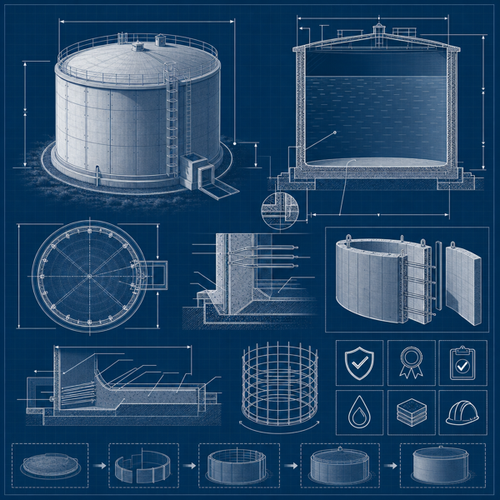
This document specifies the definitions and requirements for buried circular manholes and inspection chambers installed to a maximum depth of 6 m from ground level to the invert of the main channel and manufactured from unplasticized poly(vinyl chloride) (PVC-U), polypropylene (PP), polypropylene with mineral modifiers (PP-MD) or polyethylene (PE). These products are intended for use in traffic areas and outside the building structure (application area code “U”) for wastewater (foul wastewater, domestic wastewater, surface water). NOTE 1 Products conforming with this document are also suitable in non-traffic areas. This document is only applicable to those chamber/manhole items where the manufacturer has clearly stated in the documentation how the components must be assembled to create a complete manhole or inspection chamber. The products covered by this document comprise the following: products providing access to the drain or sewer systems by means of inspection and cleaning equipment. products designated as manholes providing additionally human access to the drain or sewer systems. NOTE 2 Manholes and inspection chambers can be subject to national regulations and/or local provisions. NOTE 3 Products conforming with this document can be installed in underground applications without additional static calculations.
- Standard23 pagesEnglish languagesale 15% off
This document specifies syntax, semantics, and decoding for video based dynamic mesh coding (V-DMC), basemesh coding, MPEG edgebreaker static mesh coding, and arithmetic coded displacement. Furthermore, this document specifies processes that can be used for reconstruction of visual volumetric media and also include additional processes such as post-decoding, pre-reconstruction, post-reconstruction, and adaptation.
- Standard484 pagesEnglish languagesale 15% off
This part of IEC 61643 applies to surge isolation transformers (SITs) dedicated to surge mitigation and for connection to 50/60 Hz power circuits and equipment rated up to
1 000 V RMS. This document covers the surge and mitigation performance of SITs with an impulse withstand voltage performance of at least 30 kV, and provides standard methods for testing and rating.
This document covers surge-related parameters but does not address typical transformer tests and parameters covered by the IEC 61558 series [13]1. This document also does not cover SIT operation under differential mode lightning surge conditions.
- Standard22 pagesEnglish languagee-Library read for1 day
This document gives guidance to organizations on planning for and addressing occupational health and safety (OH&S) risks arising from climate change and climate change action, including:
— OH&S risks which arise as a result of climate change adaptation efforts, including changing ways of working and work processes, and infrastructure upgrades;
— OH&S risks arising from climate change mitigation actions;
— OH&S opportunities arising from both climate change adaptation and mitigation actions.
This document is applicable to all organizations taking a systematic approach to addressing OH&S risks arising from climate change. It is applicable to organizations of all sizes including small and medium-sized enterprises (SMEs).
- Technical specification40 pagesEnglish languagee-Library read for1 day
- Technical specification35 pagesEnglish languagesale 15% off
This document specifies system level functionalities for the communication of interactive audio-visual scenes, i.e. the coded representation of information related to the management of data streams (synchronization, identification, description and association of stream content).
- Standard118 pagesEnglish languagesale 15% off
- Amendment9 pagesEnglish languagee-Library read for1 day
This document describes methods for the determination of sulfur and chlorine content in solid biofuels and pyrogenic biocarbon and specifies two methods for decomposition of the fuel and different analytical techniques for the quantification of the elements in the decomposition solutions. The determination of other elements such as fluorine and bromine are also possible with the methods in this document, however performance data for these elements are not provided. The use of automatic equipment is also included in this document, provided that a validation is carried out as specified and that the performance characteristics are similar to those of the method described in this document.
- Standard18 pagesEnglish languagee-Library read for1 day
This document specifies the Open Font Format (OFF) specification, including the TrueType and Compact Font Format (CFF) outline formats. Many references to both TrueType and PostScript exist throughout this document, as Open Font Format fonts combine the two technologies. The document defines data structures for various font tables and provides the necessary details for developers to build a font rendering and text layout/shaping engines in compliance with this document.
- Standard1003 pagesEnglish languagesale 15% off
This document specifies requirements and test methods for pipes and fittings which are part of piping systems for the rehabilitation, by means of renovation and trenchless replacement, of underground gas supply networks. It is applicable to polyethylene (PE) pipes, fittings and assemblies, as manufactured and as installed. It is not applicable to the existing pipeline. This document is applicable to the following technique families for renovation, intended to be used at an operating temperature of 20 °C as a reference temperature: lining with continuous pipes; lining with close-fit pipes. This document is applicable to the following technique families for trenchless replacement, intended to be used at an operating temperature of 20 °C as a reference temperature: pipe bursting and pipe extraction; horizontal directional drilling and impact moling. This document is applicable to: PE solid wall single layered pipes (nominal outside diameter, dn), including any identification stripes; PE pipes with co-extruded layers on either or both the outside and inside of the pipe (total outside diameter, dn), as specified in Annex D, where all layers have the same minimum required strength (MRS) rating. Furthermore, when used with lining with continuous pipes and trenchless replacement, this document is applicable to: PE coated pipes (outside diameter, dn) having a peelable, contiguous, thermoplastics additional layer on the outside of the pipe (“coated pipe”), as specified in Annex D. NOTE When used with lining with close-fit lining pipes, the lining pipe is reduced in the factory or on site to provide a close-fitting independent or interactive pressure pipe liner. This document is applicable to jointing by means of butt fusion and electrofusion and to fabricated and injection-moulded fittings and mechanical connections of PE. This document is not applicable to push-fit jointed discrete pipes assembled as part of the trenchless installation process.
- Standard39 pagesEnglish languagesale 15% off
- Standard42 pagesFrench languagesale 15% off
This document specifies the methodology for applying precision estimates of a test method derived from the processes specified in ISO 4259-1. In particular, it specifies the procedures for setting the property specification limits based upon test method precision where the property is determined using a specific test method, and determines the specification conformance status when there are conflicting results between supplier and receiver. Other applications of this test method precision are briefly described in principle without the associated procedures.
The procedures in this document have been designed specifically for petroleum and petroleum-related products, which are normally homogeneous. However, the procedures described in this document can also be applied to other types of homogeneous products.
This document is not applicable to non-homogenous products.
- Standard29 pagesEnglish languagee-Library read for1 day
This document specifies the methodology for the design, planning, and execution of an interlaboratory study (ILS) and calculation of precision estimates of a test method specified by the study. In particular:
it defines the relevant statistical terms,
it specifies the procedures to be adopted in the planning and execution of an ILS to determine the precision of a test method, and
it specifies the method of calculating the precision from the results of such a study.
The procedures in this document have been designed specifically for petroleum and petroleum related products, which are normally considered as homogeneous. However, the procedures described in this document can also be applied to other types of homogeneous products.
- Standard84 pagesEnglish languagee-Library read for1 day
This document provides a framework for data use in smart cities, based on five dimensions: data availability (data are available); data quality assurance (data are useful); ease of data use (data are easy to use); data use security (data are used securely); data-enabled innovation (data are used for enabling intelligent applications and services). This framework is intended to facilitate effective, sustainable, comprehensive and innovative use of data as citywide strategic resources and assets.
- Standard16 pagesEnglish languagesale 15% off
IEC TS 63346-2-2:2026 provides common rules and specific requirements for the design of low voltage DC auxiliary power systems (APSs) intended to be installed in substations, mainly covering the configuration of DC power sources, system wiring, electric equipment selection and physical layout. For the purpose of interpreting this document, a DC APS in this document is considered as follows.
Its scope covers from the low voltage AC input of the charger to the DC input points of loads. Though DC load is discussed where necessary, the load itself is beyond the scope of this document.
Unless particularly stated, DC APS refers to the system using lead-acid and nickel-cadmium cells which are connected in series. The system using parallel cells can implement this document by reference.
Substations in this document refer to those which are part of an electrical system and contain equipment that either receives and distributes electrical energy or transforms voltages to the levels required by the loads they supply, or both.
This document does not apply to the design of any of the following: traction substation, which have different power supply requirements, such as unbalanced load power supply and harmonic behaviour;
offshore substations, as factors such as waves, typhoons, salt spray, etc. need to be taken into account, which have different requirements for power supply and equipment selection; the substation connecting a nuclear power plant to the grid and its associated LV APS integrated with the nuclear power plant.
- Technical specification35 pagesEnglish languagesale 15% off
This document specifies a calculation method to determine the thermal transmittance (U value) of glass with flat and parallel surfaces. This document applies to uncoated glass (including glass with structured surfaces, e.g. patterned glass), coated glass and materials not transparent in the far infrared which is the case for soda lime glass products, borosilicate glass, glass ceramic, alkaline earth silicate glass and alumino silicate glass. It applies also to multiple glazing comprising such glasses or materials, or both. It does not apply to multiple glazing which include in the gas space sheets or foils that are far infrared transparent. Vacuum insulating glass (VIG) is excluded from the scope of this document. To determine the U value of VIG, reference can be made to ISO 10291 or ISO 19916-1. The procedure specified in this document determines the U value in the central area of glazing. The edge effects due to the thermal bridge through the spacer of an insulating glass unit or through the window frame are not included. Furthermore, energy transfer due to solar radiation is not taken into account. The effects of Georgian and other bars are excluded from the scope of this document. NOTE ISO 10077-1 provides a methodology for calculating the overall U value of windows, doors and shutters, taking account of the U value calculated for the glass components according to this document. Also excluded from the calculation methodology are any effects due to gases that absorb infrared radiation in the 5 µm to 50 µm range.
- Standard17 pagesEnglish languagesale 15% off
- Standard9 pagesEnglish languagesale 15% off
- Standard9 pagesFrench languagesale 15% off
- Standard8 pagesEnglish languagesale 15% off
- Standard8 pagesFrench languagesale 15% off
This document specifies a test method for the sampling and analysis of airborne organic isocyanate (NCO) compounds in workplace air. The method covers organic compounds containing free isocyanate functional groups, including monomeric, oligomeric, prepolymeric and polymeric isocyanates, and addresses the measurement of total isocyanate groups in air samples collected for the assessment of occupational exposure. The method is suitable for personal air sampling in the breathing zone for the determination of time-weighted average concentrations over sampling periods ranging from approximately 10 min to 8 h, although it can be applied to shorter sampling periods with high isocyanate air levels. It can also be used for background or fixed-location air sampling; however, due to aerodynamic effects, samplers designed for personal sampling do not necessarily exhibit the same collection characteristics when used for other purposes. It covers the measurement of airborne organic isocyanates over a concentration range of approximately 0,1 µg/m3 to 140 µg/m3 for a nominal air sample volume of 15 l; under the conditions specified in this document, typical qualitative and quantitative detection limits correspond to approximately 0,07 µg/m3 and 0,3 µg/m3, respectively, for a 15 l air sample. This document does not apply to the simultaneous determination of isocyanates and amines, nor to modified methods employing alternative sampling devices or detection techniques not described in this document.
- Standard33 pagesEnglish languagesale 15% off
- Draft39 pagesEnglish languagee-Library read for1 day
IEC 60335-2-2:2026 deals with the safety of electric vacuum cleaners and water suction cleaning appliances for household and similar purposes, their rated voltage being not more than 250 V for single phase (AC) supplied appliances, direct current (DC) supplied appliances and battery-operated appliances and 480 V for multi-phase centrally-sited vacuum cleaners. This standard also applies to vacuum cleaners for animal grooming, centrally-sited vacuum cleaners, and automatic battery-operated cleaners.
This standard also applies to spray extraction appliances in which
– the pressure of the employed liquid solution does not exceed 2,5 MPa;
– the product of the pressure (in MPa) and the flow of liquid solution (in litres per minute) do not exceed 100; and
– the temperature of the liquid solution at the spray nozzle outlet does not exceed 60 °C.
This standard also applies to vacuum cleaners and water suction cleaning appliances provided with a blowing function or inflating function.
This standard also applies to motorized cleaning heads and current-carrying hoses associated with a particular vacuum cleaner or water suction cleaning appliance.
Appliances not intended for normal household use, but which nevertheless can be a source of danger to the public, such as appliances intended to be used by laypersons in shops and other premises for normal housekeeping purposes, are within the scope of this standard.
Examples of appliances for household use are appliances for typical housekeeping functions used in the household environment that can also be used by non-expert users for typical intermittent housekeeping functions:
– in shops, schools and other similar working environments;
– in farm houses;
– by clients in hotels, motels and other residential type environments;
– in bed and breakfast type environments.
Household environments include the dwelling and its associated buildings, the garden, etc.
As far as is practicable, this standard deals with the common hazards presented by appliances that are encountered by all persons in and around the home. However, in general, it does not take into account
– persons (including children) whose physical, sensory or mental capabilities; or lack of experience and knowledge prevents them from using the appliance safely without supervision or instruction;
– children playing with the appliance.
Attention is drawn to the fact that
– for appliances intended to be used in vehicles or on board ships or aircraft, additional requirements can be necessary;
– in many countries, additional requirements are specified by the national health authorities, the national authorities responsible for the protection of labour, the national water supply authorities and similar authorities.
This standard does not apply to
– appliances intended exclusively for industrial purposes;
– appliances intended to be used in locations where special conditions prevail, such as the presence of a corrosive or explosive atmosphere (dust, vapour or gas);
– wet and dry vacuum cleaners, including power brush, for commercial use (IEC 60335-2-69);
– floor treatment and wet scrubbing machines, including rug shampooers, for household and similar use (IEC 60335-2-10);
– hand-held mains-operated garden blowers, vacuums and blower vacuums (IEC 60335 2 100, IEC 62841-4-6);
– spray extraction machines for commercial use (IEC 60335-2-68);
– high-pressure cleaners and steam cleaners (with a rated pressure not less than 2,5 MPa) (IEC 60335-2-79);
– appliances having vacuum-pressure functions for skin care (IEC 60335-2-115).
This eighth edition cancels and replaces the seventh edition published in 2019. This edition constitutes a technical revision.
This edition includes the following significant technical changes with respect to the previous edition:
– alignment with IEC 60335-1:2020;
– conversion of some notes to normative text (Clause 1);
– addition of multi-phase central vacuum cleaners to the scope (Clause 1);
–
- Standard37 pagesEnglish languagesale 15% off
- Standard84 pagesEnglish languagesale 15% off
- Standard295 pagesEnglish languagesale 15% off
This document specifies the maximum percentage content of alloying elements and impurities present in wrought aluminium and aluminium alloys which are fabricated into materials and articles designed to be in contact with foodstuff. It contains provisions for the demonstration of conformity of products with the present standard.
NOTE Materials include semi-finished products. Articles are finished goods.
- Standard9 pagesEnglish languagee-Library read for1 day
IEC TS 62607-4-9:2026, which is a Technical Specification, establishes a standardized method for assembling
• coin-cell EDLCs
in order to characterize the electrochemical key control characteristic of carbon nanomaterials.
The coin-cell EDLC is fabricated through sequential steps: electrode slurry preparation (mixing), coating, rolling, cutting, weighing, and final assembly.
• The document specifies the assembly process and data recording.
• The document is applicable for carbon nanomaterials used in EDLC as active material or conductive agents, such as nanoporous activated carbon, carbon aerogel, carbon nanotube, carbon black, graphene, nano graphite sheet, vapour-grown carbon fibre and so on.
• Typical application areas of this method are research, manufacturer and downstream user to guide material processing and quality control
- Technical specification27 pagesEnglish languagesale 15% off
Benefits

Full Standards Solution
Our catalog includes not only latest standards but also full meta information about related standardization project lifecycle.

Cost Effective
Our PRICE MATCH GUARANTEE policy with multi-level volume discounts gives our clients the best option in the market. In addition, you can get access to the standards for 3, 10, or 30 days.

Stay Notified
Get alerted to the latest revisions and new standards in the Weekly Newsletter. Standards are constantly changing. Don’t miss a revision that can impact your business.
Frequently Asked Questions
While can’t speak to your particular circumstance generally no. You get the same standard at a cheaper price!
We provide licenses to standards documents adopted by Slovenian Institute for Standardization (SIST). These are exactly the same as original works but are preceded by cover pages acknowledging their adoption. For instance, the international standard document ISO 8601:2013 is adopted by European Committee for Standardization (CEN) as the European Standard document EN ISO 3166-1:2014 and subsequently adopted by SIST as Slovenian Standard document SIST EN ISO 8601-1:2014.
Yes, the intended recipient for which a license has been granted may print documents for their personal use. No other persons may print, receive, inspect, duplicate, or otherwise consume printed material.
Documents are licensed to individuals and must not be made accessible to any person who the license was not purchased for (including the purchaser). This would preclude posting the documents in any manner that would allow distribution. This includes but not exclusively public or private network shares, wikis, FTP, messaging services, etc.
A license grants 1 persons exclusive access to purchased document in perpetuity. Licenses are not transferable. If for instance you have team of five individuals that need access to a document then five licenses must be purchased, one for each member. If a new team member is added regardless of the departure of any existing member a new license must be acquired for that individual. If you know you will need multiple licenses, consider purchasing several at one time as we offer volume discounts. See: Do you offer discounts?
iTeh Standards already offers substantial discounts in most cases in comparison to original publishing organizations. Furthermore, we offer volume discounts for buying multiple licenses. Simply multiply the price of the publication according to the relevant discount.
- 2-3 licenses - 15% discount
- 4-5 licenses - 30% discount
- 6-10 licenses - 50% discount
- more than 10 licenses - 60% discount
About Us
Standards work, redesigned for the way teams actually work.
iTeh builds the digital infrastructure of the standards industry. Together with the Slovenian Institute for Standardization (SIST) and a growing network of publishers and certification partners, we run standards.iteh.ai — where engineers, procurement teams, compliance officers and standardization institutes find, buy, read, annotate and reuse the standards their work depends on. Our platform turns a static catalog into a workplace your team will actually open every day.
Advantage
- AI-first. Ask any standard a question. Search the catalog semantically. Connect ChatGPT, Claude, Perplexity or your own agents through our MCP endpoints.
- Engineering Workplace. Highlight, draw, comment and share — page-accurate, saved automatically, publishable to your whole team in one click.
- Company-wide licensing. One account, every employee, controlled by your administrator — no more chasing PDFs across inboxes.
- e-Library. Subscription access to live standards collections — pay for the shelf, not for every single document.
- Always on, always current. Continuous platform updates, 24/7 support, no version-upgrade projects.