


ASTM D2221-01(2015)
(Test Method)Standard Test Method for Creep Properties of Package Cushioning Materials
Standard Test Method for Creep Properties of Package Cushioning Materials
SIGNIFICANCE AND USE
5.1 This test method determines the extent and nature of cushion thickness change under static load. Creep data obtained by this test method are applicable to the cushion under the conditions of the particular test and are not necessarily the same as obtained in a complete pack in actual packaging environments. Data may be affected by magnitude of static load, specimen area, shape, and thickness, by varying ambient conditions of temperature, humidity, by friction in the movable platen guide system, and by actual cushion thickness. Vibration in the vicinity of the test fixtures may also influence data results.
SCOPE
1.1 This test method covers the determination of creep properties of package cushioning materials. It is applicable to materials available in bulk, sheet, or molded form used for the cushioning of articles during storage, handling, and shipment.
1.2 The values stated in inch-pound units are to be regarded as standard. The values given in parentheses are mathematical conversions to SI units that are provided for information only and are not considered standard.
1.3 This standard does not purport to address all of the safety concerns, if any, associated with its use. It is the responsibility of the user of this standard to establish appropriate safety and health practices and determine the applicability of regulatory limitations prior to use.
General Information
Buy Standard

Standards Content (Sample)
NOTICE: This standard has either been superseded and replaced by a new version or withdrawn.
Contact ASTM International (www.astm.org) for the latest information
Designation: D2221 − 01 (Reapproved 2015)
Standard Test Method for
Creep Properties of Package Cushioning Materials
This standard is issued under the fixed designation D2221; the number immediately following the designation indicates the year of
original adoption or, in the case of revision, the year of last revision.Anumber in parentheses indicates the year of last reapproval.A
superscript epsilon (´) indicates an editorial change since the last revision or reapproval.
This standard has been approved for use by agencies of the U.S. Department of Defense.
1. Scope 3.1.2 permanent set—the permanent change in thickness of
anunloadedcushionasaresultofanappliedcompressiveload
1.1 This test method covers the determination of creep
for any given time interval and any given unloaded recovery
properties of package cushioning materials. It is applicable to
time period.
materials available in bulk, sheet, or molded form used for the
cushioning of articles during storage, handling, and shipment.
4. Summary of Test Method
1.2 The values stated in inch-pound units are to be regarded
4.1 The test apparatus consists of a suitable testing device
as standard. The values given in parentheses are mathematical
having a base plate and a guided movable platen which can be
conversions to SI units that are provided for information only
loaded with weights.The loaded movable platen is placed on a
and are not considered standard.
cushion to simulate static compressive loading of cushioning
1.3 This standard does not purport to address all of the material in actual packaging. By measuring the change in
thickness of the loaded cushion with time, creep properties of
safety concerns, if any, associated with its use. It is the
responsibility of the user of this standard to establish appro- the cushioning material can be obtained.
priate safety and health practices and determine the applica-
5. Significance and Use
bility of regulatory limitations prior to use.
5.1 This test method determines the extent and nature of
cushion thickness change under static load. Creep data ob-
2. Referenced Documents
tained by this test method are applicable to the cushion under
2.1 ASTM Standards:
the conditions of the particular test and are not necessarily the
D4332Practice for Conditioning Containers, Packages, or
same as obtained in a complete pack in actual packaging
Packaging Components for Testing
environments. Data may be affected by magnitude of static
E105Practice for Probability Sampling of Materials
load, specimen area, shape, and thickness, by varying ambient
E122PracticeforCalculatingSampleSizetoEstimate,With
conditionsoftemperature,humidity,byfrictioninthemovable
Specified Precision, the Average for a Characteristic of a
platenguidesystem,andbyactualcushionthickness.Vibration
Lot or Process
in the vicinity of the test fixtures may also influence data
results.
3. Terminology
6. Apparatus
3.1 Definitions of Terms Specific to This Standard:
3.1.1 creep—the deformation of a material occurring with
6.1 Movable, Guided Platen, capable of being weighted to
time and due to an externally applied constant stress. For achieve the desired loading along with a base to support the
cushioning materials specifically, it may be defined as the
sample throughout the duration of the test. Two such assem-
change in thickness of a cushion under static compressive load blies are shown in Fig. 1 and Fig. 2.
over a period of time.
6.2 Static Load Box Fixture (Fig. 1), consisting of a mov-
able guided platen and an outer box that shall act as the guide
and the base plate for supporting the sample.
1 3
This test method is under the jurisdiction of ASTM Committee D10 on
6.2.1 Base Plate (Outer Box), may be constructed of ⁄4 in.
Packaging and is the direct responsibility of Subcommittee D10.13 on Interior
(19.0 mm) minimum white pine and fabricated to reduce
Packaging.
swellingwhichmayoccurathighhumidity.Aflatrigidplateof
Current edition approved April 1, 2015. Published May 2015. Originally
appropriate dimensions is placed on the inside bottom surface
approved in 1963. Last previous edition approved in 2010 as D2221–01 (2010).
DOI: 10.1520/D2221–01R15.
and used as the base plate.The plate can be made of a material
For referenced ASTM standards, visit the ASTM website, www.astm.org, or
such as aluminum, steel, rigid plastic sheeting or glass.
contact ASTM Customer Service at service@astm.org. For Annual Book of ASTM
6.2.2 Movable Guided Platen (Inner Box), may be loaded
Standards volume information, refer to the standard’s Document Summary page on
the ASTM website. with weights (for example, lead shot or molded lead weights),
Copyright © ASTM International, 100 Barr Harbor Drive, PO Box C700, West Conshohocken, PA 19428-2959. United States
D2221 − 01 (2015)
NOTE 1—All dimensions are for reference only and are dependent on
the materials tested.
FIG. 2 Typical Single Point Creep Apparatus
without binding. The rod shall be attached to the platen so as
NOTE 1—All dimensions are for reference only and are dependent on
tolimitlateralmotion.(Theweightofbothplatenandrodshall
the materials tested.
be constructed to achieve the minimum static loading for
Inside Dimensions of Outer Box
165 (+2,−0) × 165 (+2,−0) × 254 (±3) mm
original thickness measurement in 9.2.)Weights may be added
mm 2 162 165 203 254
to the platen top surface to achieve the desired static loading.
in. 0.08 6.37 6.50 8 10
6.3.2 Measurements shall be taken from the top of the rod
FIG. 1 Typical Static Load Box Creep Apparatus
with a dial micrometer or other similar device capable of
measurement to 0.01 in. (0.3 mm).
6.4 Flat Rigid Plate, for measuring specimen thickness (see
and fabricated in the same manner as described in 6.2.1.Aflat
9.2)shouldbeconstructedtoyielda0.025psi(0.17kPa)static
rigid plate similar to that described in 6.2.1 is placed between
load. Plates referenced in 6.2.1 and 6.2.2 used with the static
the top of the test specimen and the movable platen and serves
load box may be utilized if constructed to the proper weight
as a reference for measuring the height of the specimen.
required to achieve the desired static load.
6.2.3 Two means of measurement, two position and four
position,maybeutilized.Amicrometerorsteelrulecapableof 7. Test Specimens
measurement to 0.01 in. (0.3 mm) shall be utilized.
7.1 Test specimens shall be right square prisms or right
6.2.3.1 Two Position—A vertical line, scribed at the center
cylinders with the lateral dimensions at least the same as the
of both (movable and base) flat, rigid plate edges (Fig. 1)
original thickness, and with minimum dimensions of not less
serves as location references for specimen thickness measure-
than 2 by 2 by 1 in. (51 by 51 by 25 mm) thick. The preferred
ments (distance between the plates) at various time intervals.
size is 6 by 6 by 4 in. (152 by 152 by 102 mm) thick. If the
Measurementsaretakenattheverticalscribedlinesatboththe
cushioning material, as supplied, is less than 1 in. (25.4 mm)
front and back of the box.
thick, the required thickness may be obtained by using two or
6.2.3.2 Four Position—Measurements are taken at the four
more layers of the material. For thin gage materials requiring
box corners for specimen thickness measurements (see
the stacking of several layers to achieve the desired specimen
6.2.3.1).
thickness, interleaving between layers with light weight,
6.3 The single point fixture shall consist of a support noncompressible,flat,rigidplatescanhelpstabilizethestacked
structureguidingarodperpendicularlyattachedtoaplaten(see specimen.However,thecumulativethicknessesandweightsof
Fig. 2). these plates must be accounted for in all thickness measure-
6.3.1 The support structure shall be constructed in such a ments before calculating any values described in Section 10.
manner as to keep the rod and platen perpendicular to the base Specimens with larger areas are recommended whenever
D2221 − 01 (2015)
possible and may be dictated by the apparatus used to measure period, record as the preworked thickness, T , the thickness of
p
creep. Fiber length, pore size, or the nature of a material may the specimen, as determined in 9.2.
also be determining factors regarding specimen size.
9.4 Loading of Specimen—Using either of the fixtures
7.2 The number of specimens tested as a sample may vary described in Section 6, center the rigid plate on the specimen
widely, depending on the intended use of the data. It is and apply the desired static load (weight of the rigid plate plus
recommended that at least four specimens be used for the that of the movable platen plus the lead shot or molded
initial sample of a material. Then, depending on the accuracy weights) evenly and gently to the entire upper surface of each
and degree of certainty required, this sample size may be specimen. Start to measure or determine the thickness of the
increased or decreased. To ensure better representation of the specimen while under load, 60 6 5 s after the load has been
sample, individual specimens should be selected by systematic applied. Determine the thickness by averaging the vertical
randomization. This can be done by assigning a consecutive perpendicular distance between the plates using either the two
number to each of the specimens of the sample, and then or four position measuring method (see 6.2.3) for the guided
selectingthespecimenswhichhavenumbersthatcorrespondto platen fixture, or by measuring the height of the rod in the
a series drawn by lottery. Sampling procedures for selecting single point fixture. Record this thickness as the initial thick-
specimens are discussed in Practice E105. Procedures for ness under load, T.
i
determiningthenumberofspecimensrequiredforeachsample
NOTE 1—Since creep tes
...
This document is not an ASTM standard and is intended only to provide the user of an ASTM standard an indication of what changes have been made to the previous version. Because
it may not be technically possible to adequately depict all changes accurately, ASTM recommends that users consult prior editions as appropriate. In all cases only the current version
of the standard as published by ASTM is to be considered the official document.
Designation: D2221 − 01 (Reapproved 2010) D2221 − 01 (Reapproved 2015)
Standard Test Method for
Creep Properties of Package Cushioning Materials
This standard is issued under the fixed designation D2221; the number immediately following the designation indicates the year of
original adoption or, in the case of revision, the year of last revision. A number in parentheses indicates the year of last reapproval. A
superscript epsilon (´) indicates an editorial change since the last revision or reapproval.
This standard has been approved for use by agencies of the U.S. Department of Defense.
1. Scope
1.1 This test method covers the determination of creep properties of package cushioning materials. It is applicable to materials
available in bulk, sheet, or molded form used for the cushioning of articles during storage, handling, and shipment.
1.2 The values stated in inch-pound units are to be regarded as standard. The values given in parentheses are mathematical
conversions to SI units that are provided for information only and are not considered standard.
1.3 This standard does not purport to address all of the safety concerns, if any, associated with its use. It is the responsibility
of the user of this standard to establish appropriate safety and health practices and determine the applicability of regulatory
limitations prior to use.
2. Referenced Documents
2.1 ASTM Standards:
D4332 Practice for Conditioning Containers, Packages, or Packaging Components for Testing
E105 Practice for Probability Sampling of Materials
E122 Practice for Calculating Sample Size to Estimate, With Specified Precision, the Average for a Characteristic of a Lot or
Process
3. Terminology
3.1 Definitions of Terms Specific to This Standard:
3.1.1 creep—the deformation of a material occurring with time and due to an externally applied constant stress. For cushioning
materials specifically, it may be defined as the change in thickness of a cushion under static compressive load over a period of time.
3.1.2 permanent set—the permanent change in thickness of an unloaded cushion as a result of an applied compressive load for
any given time interval and any given unloaded recovery time period.
4. Summary of Test Method
4.1 The test apparatus consists of a suitable testing device having a base plate and a guided movable platen which can be loaded
with weights. The loaded movable platen is placed on a cushion to simulate static compressive loading of cushioning material in
actual packaging. By measuring the change in thickness of the loaded cushion with time, creep properties of the cushioning
material can be obtained.
5. Significance and Use
5.1 This test method determines the extent and nature of cushion thickness change under static load. Creep data obtained by
this test method are applicable to the cushion under the conditions of the particular test and are not necessarily the same as obtained
in a complete pack in actual packaging environments. Data may be affected by magnitude of static load, specimen area, shape, and
thickness, by varying ambient conditions of temperature, humidity, by friction in the movable platen guide system, and by actual
cushion thickness. Vibration in the vicinity of the test fixtures may also influence data results.
This test method is under the jurisdiction of ASTM Committee D10 on Packaging and is the direct responsibility of Subcommittee D10.13 on Interior Packaging.
Current edition approved April 1, 2015. Published January 2010May 2015. Originally approved in 1963. Last previous edition approved in 20012010 as
D2221 – 01.D2221 – 01 (2010). DOI: 10.1520/D2221–01R10.10.1520/D2221–01R15.
For referenced ASTM standards, visit the ASTM website, www.astm.org, or contact ASTM Customer Service at service@astm.org. For Annual Book of ASTM Standards
volume information, refer to the standard’s Document Summary page on the ASTM website.
Copyright © ASTM International, 100 Barr Harbor Drive, PO Box C700, West Conshohocken, PA 19428-2959. United States
D2221 − 01 (2015)
6. Apparatus
6.1 Movable, Guided Platen, capable of being weighted to achieve the desired loading along with a base to support the sample
throughout the duration of the test. Two such assemblies are shown in Fig. 1 and Fig. 2.
6.2 Static Load Box Fixture (Fig. 1), consisting of a movable guided platen and an outer box that shall act as the guide and the
base plate for supporting the sample.
6.2.1 Base Plate (Outer Box), may be constructed of ⁄4 in. (19.0 mm) minimum white pine and fabricated to reduce swelling
which may occur at high humidity. A flat rigid plate of appropriate dimensions is placed on the inside bottom surface and used
as the base plate. The plate can be made of a material such as aluminum, steel, rigid plastic sheeting or glass.
6.2.2 Movable Guided Platen (Inner Box), may be loaded with weights (for example, lead shot or molded lead weights), and
fabricated in the same manner as described in 6.2.1. A flat rigid plate similar to that described in 6.2.1 is placed between the top
of the test specimen and the movable platen and serves as a reference for measuring the height of the specimen.
6.2.3 Two means of measurement, two position and four position, may be utilized. A micrometer or steel rule capable of
measurement to 0.01 in. (0.3 mm) shall be utilized.
6.2.3.1 Two Position—A vertical line, scribed at the center of both (movable and base) flat, rigid plate edges (Fig. 1) serves as
location references for specimen thickness measurements (distance between the plates) at various time intervals. Measurements are
taken at the vertical scribed lines at both the front and back of the box.
6.2.3.2 Four Position—Measurements are taken at the four box corners for specimen thickness measurements (see 6.2.3.1).
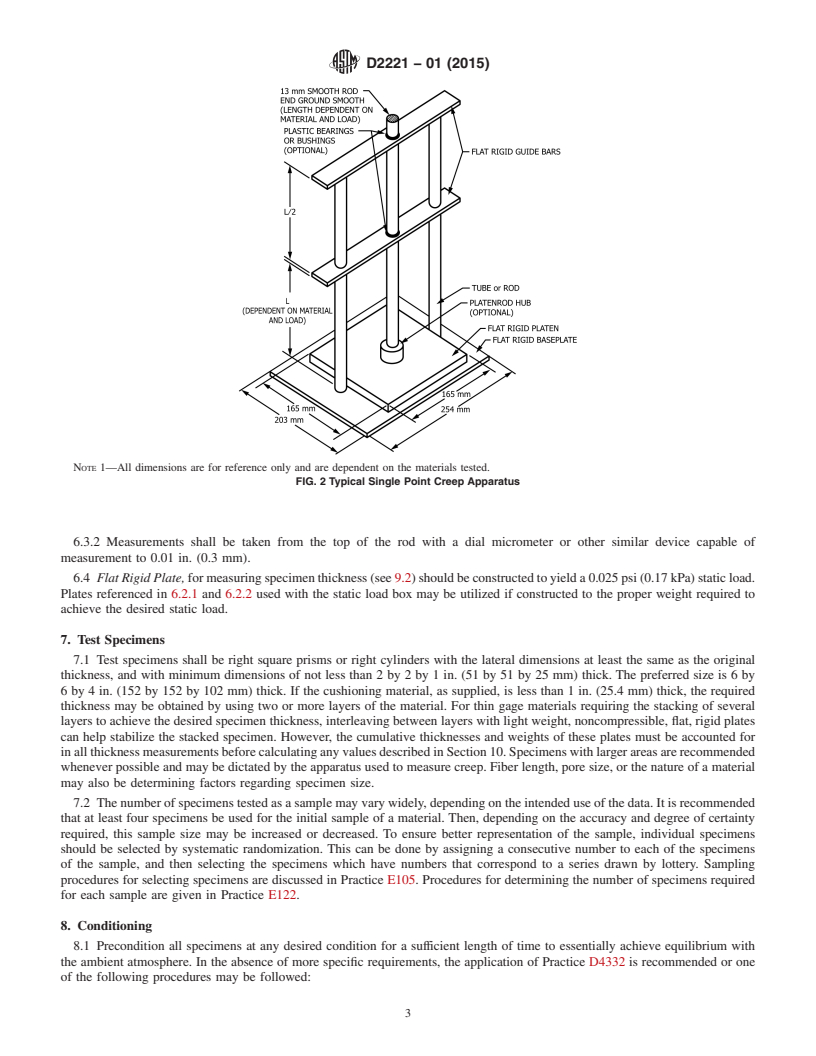
6.3 The single point fixture shall consist of a support structure guiding a rod perpendicularly attached to a platen (see Fig. 2).
6.3.1 The support structure shall be constructed in such a manner as to keep the rod and platen perpendicular to the base without
binding. The rod shall be attached to the platen so as to limit lateral motion. (The weight of both platen and rod shall be constructed
to achieve the minimum static loading for original thickness measurement in 9.2.) Weights may be added to the platen top surface
to achieve the desired static loading.
NOTE 1—All dimensions are for reference only and are dependent on the materials tested.
Inside Dimensions of Outer Box
165 (+2,−0) × 165 (+2,−0) × 254 (±3) mm
mm 2 162 165 203 254
in. 0.08 6.37 6.50 8 10
FIG. 1 Typical Static Load Box Creep Apparatus
D2221 − 01 (2015)
NOTE 1—All dimensions are for reference only and are dependent on the materials tested.
FIG. 2 Typical Single Point Creep Apparatus
6.3.2 Measurements shall be taken from the top of the rod with a dial micrometer or other similar device capable of
measurement to 0.01 in. (0.3 mm).
6.4 Flat Rigid Plate, for measuring specimen thickness (see 9.2) should be constructed to yield a 0.025 psi (0.17 kPa) static load.
Plates referenced in 6.2.1 and 6.2.2 used with the static load box may be utilized if constructed to the proper weight required to
achieve the desired static load.
7. Test Specimens
7.1 Test specimens shall be right square prisms or right cylinders with the lateral dimensions at least the same as the original
thickness, and with minimum dimensions of not less than 2 by 2 by 1 in. (51 by 51 by 25 mm) thick. The preferred size is 6 by
6 by 4 in. (152 by 152 by 102 mm) thick. If the cushioning material, as supplied, is less than 1 in. (25.4 mm) thick, the required
thickness may be obtained by using two or more layers of the material. For thin gage materials requiring the stacking of several
layers to achieve the desired specimen thickness, interleaving between layers with light weight, noncompressible, flat, rigid plates
can help stabilize the stacked specimen. However, the cumulative thicknesses and weights of these plates must be accounted for
in all thickness measurements before calculating any values described in Section 10. Specimens with larger areas are recommended
whenever possible and may be dictated by the apparatus used to measure creep. Fiber length, pore size, or the nature of a material
may also be determining factors regarding specimen size.
7.2 The number of specimens tested as a sample may vary widely, depending on the intended use of the data. It is recommended
that at least four specimens be used for the initial sample of a material. Then, depending on the accuracy and degree of certainty
required, this sample size may be increased or decreased. To ensure better representation of the sample, individual specimens
should be selected by systematic randomization. This can be done by assigning a consecutive number to each of the specimens
of the sample, and then selecting the specimens which have numbers that correspond to a series drawn by lottery. Sampling
procedures for selecting specimens are discussed in Practice E105. Procedures for determining the number of specimens required
for each sample are given in Practice E122.
8. Conditioning
8.1 Precondition all specimens at any desired condition for a sufficient length of time to essentially achieve equilibrium with
the ambient atmosphere. In the absence of more specific requirements, the application of Practice D4332 is recommended or one
of the following procedures may be followed:
D2221 − 01 (2015)
8.2 Precondition all specimens at 35 6 2 % relative humidity at 73.4 6 3.6°F (23 6 2°C) maximum for 24 h and then condition
and test at 73.4 6 3.6°F (23 6 2°C) and 50 6 2 % relative humidity. The length of conditioning shall be a minimum of 16 h, or
until the differences between two successive weights of the
...
Questions, Comments and Discussion
Ask us and Technical Secretary will try to provide an answer. You can facilitate discussion about the standard in here.