


ASTM B851-04(2014)
(Specification)Standard Specification for Automated Controlled Shot Peening of Metallic Articles Prior to Nickel, Autocatalytic Nickel, or Chromium Plating, or as Final Finish
Standard Specification for Automated Controlled Shot Peening of Metallic Articles Prior to Nickel, Autocatalytic Nickel, or Chromium Plating, or as Final Finish
ABSTRACT
This specification covers the requirements for automated, controlled shot peening of metallic articles prior to electrolytic or autocatalytic deposition of nickel or chromium, or as a final finish, using shot made of cast steel, conditioned cut wire, or ceramic media. The process is applicable to those materials on which test work has shown it to be beneficial within given intensity ranges. It is not suitable for brittle materials. Hand peening and rotary flap peening are excluded specifically. Shot peening induces residual compressive stresses in the surface and near-surface layers of metallic articles, controlling or limiting the reduction in fatigue properties that occurs from nickel or chromium plating of the article, or the fatigue properties of unplated articles. It is a process for cold working surfaces by bombarding the product with shot of a solid and spherical nature propelled at a relatively high velocity. Cast steel, cut wire, and ceramic shot shall all be spherical in shape and shall all be free of sharp edges, corners, and broken pieces. Prior to shot peening, the following operations shall be done first: heat treatment, machining, grinding, flaw test, crack test, corrosion detection, cleaning, and masking. Peened surfaces shall be uniform in appearance and completely dented so that the original surface is obliterated entirely. After shot peening, the following methods shall be done: residual shot removal, surface finishing, chemical cleaning of nonferrous metals and their alloys, thermal and heat treatments, and corrosion protection.
SIGNIFICANCE AND USE
5.1 Shot peening is a process for cold working surfaces by bombarding the product with shot of a solid and spherical nature propelled at a relatively high velocity. In general, shot peening will increase the fatigue life of a product that is subject to bending or torsional stress. It will improve resistance to stress corrosion cracking. It can be used to form parts or correct their shapes. See Appendix X1 for additional information.
5.2 It is essential that the shot peening process parameters be controlled rigidly to ensure repeatability from part to part and lot to lot.
5.3 This specification covers techniques and methods necessary for proper control of the shot peening process.
SCOPE
1.1 This specification covers the requirements for automated, controlled shot peening of metallic articles prior to electrolytic or autocatalytic deposition of nickel or chromium, or as a final finish, using shot made of cast steel, conditioned cut wire, or ceramic media. The process is applicable to those materials on which test work has shown it to be beneficial within given intensity ranges. It is not suitable for brittle materials. Hand peening and rotary flap peening are excluded specifically.
1.2 Shot peening induces residual compressive stresses in the surface and near-surface layers of metallic articles, controlling or limiting the reduction in fatigue properties that occurs from nickel or chromium plating of the article, or the fatigue properties of unplated articles.
1.3 The values stated in SI units are to be regarded as standard. No other units of measurement are included in this standard.
1.4 This standard does not purport to address all of the safety concerns, if any, associated with its use. It is the responsibility of the user of this standard to establish appropriate safety and health practices and determine the applicability of regulatory limitations prior to use.
General Information
Buy Standard
Standards Content (Sample)
NOTICE: This standard has either been superseded and replaced by a new version or withdrawn.
Contact ASTM International (www.astm.org) for the latest information
Designation:B851 −04 (Reapproved 2014)
Standard Specification for
Automated Controlled Shot Peening of Metallic Articles
Prior to Nickel, Autocatalytic Nickel, or Chromium Plating,
or as Final Finish
This standard is issued under the fixed designation B851; the number immediately following the designation indicates the year of
original adoption or, in the case of revision, the year of last revision. A number in parentheses indicates the year of last reapproval. A
superscript epsilon (´) indicates an editorial change since the last revision or reapproval.
1. Scope B320 Practice for Preparation of Iron Castings for Electro-
plating
1.1 This specification covers the requirements for
B322 Guide for Cleaning Metals Prior to Electroplating
automated, controlled shot peening of metallic articles prior to
B607 Specification forAutocatalytic Nickel Boron Coatings
electrolytic or autocatalytic deposition of nickel or chromium,
for Engineering Use
or as a final finish, using shot made of cast steel, conditioned
B650 Specification for Electrodeposited Engineering Chro-
cut wire, or ceramic media. The process is applicable to those
mium Coatings on Ferrous Substrates
materials on which test work has shown it to be beneficial
B656 Guide for Autocatalytic (Electroless) Nickel-
within given intensity ranges. It is not suitable for brittle
Phosphorus Deposition on Metals for Engineering Use
materials. Hand peening and rotary flap peening are excluded
(Discontinued 2000) (Withdrawn 2000)
specifically.
B689 Specification for Electroplated Engineering Nickel
1.2 Shot peening induces residual compressive stresses in
Coatings
the surface and near-surface layers of metallic articles, control-
B733 Specification for Autocatalytic (Electroless) Nickel-
ling or limiting the reduction in fatigue properties that occurs
Phosphorus Coatings on Metal
from nickel or chromium plating of the article, or the fatigue
E11 Specification for Woven Wire Test Sieve Cloth and Test
properties of unplated articles.
Sieves
1.3 The values stated in SI units are to be regarded as E165 Practice for Liquid Penetrant Examination for General
Industry
standard. No other units of measurement are included in this
standard. E709 Guide for Magnetic Particle Testing
2.2 Federal Standards:
1.4 This standard does not purport to address all of the
QQ-N-290 Nickel Plating (Electrodeposited)
safety concerns, if any, associated with its use. It is the
QQ-C-320 Chromium Plating (Electrodeposited)
responsibility of the user of this standard to establish appro-
priate safety and health practices and determine the applica-
2.3 Military Standards:
bility of regulatory limitations prior to use.
MIL-S-851 Steel Grit, Shot, and Cut Wire Shot, and Iron
Grit and Shot Blast Cleaning and Peening
2. Referenced Documents
MIL-S-13165 Shot Peening of Metal Parts
MIL-C-26074 Coating, Electroless Nickel
2.1 ASTM Standards:
MIL-STD-45662 Calibration System Requirements
B183 Practice for Preparation of Low-Carbon Steel for
Electroplating
2.4 SAE Standards:
B242 Guide for Preparation of High-Carbon Steel for Elec-
SAE J441 Cut Steel Wire Shot
troplating
SAE J442 Test Strip, Holder and Gage for Shot Peening
SEA J827 Cast Steel Shot
SAE J1830 Size, Classification and Characteristics of Ce-
This specification is under the jurisdiction of ASTM Committee B08 on
ramic Shot for Peening
Metallic and Inorganic Coatings and is the direct responsibility of Subcommittee
B08.02 on Pre Treatment.
Current edition approved Nov. 1, 2014. Published November 2014. Originally
approved in 1994. Discontinued January 2004 and reinstated in 2004 as B851–04. The last approved version of this historical standard is referenced on
Last previous edition approved in 2009 as B851–09. DOI: 10.1520/B0851-04R14. www.astm.org.
2 4
For referenced ASTM standards, visit the ASTM website, www.astm.org, or AvailablefromStandardizationDocumentsOrderDesk,Bldg.4SectionD,700
contact ASTM Customer Service at service@astm.org. For Annual Book of ASTM Robbins Ave., Philadelphia, PA 19111-5094, Attn: NPODS.
Standards volume information, refer to the standard’s Document Summary page on Available from Society of Automotive Engineers, 400 Commonwealth Drive,
the ASTM website. Warrendale, PA 15096.
Copyright © ASTM International, 100 Barr Harbor Drive, PO Box C700, West Conshohocken, PA 19428-2959. United States
B851−04 (2014)
3. Terminology
3.1 Definitions:
3.1.1 Almen strip—UNS G10700 carbon steel specimens
that are used to calibrate the energy of a shot peening stream
(see Fig. 1).
3.1.2 Almen strip holding fixture—a fixture for holding
Almen strips in suitable locations that represent the position
andangularorientationofthesurfacesofapartwhereintensity
is to be determined and verified (see Fig. 2).
3.1.3 arc height—flat Almen strips, when subjected to a
stream of shot moving at an adequate velocity, bending in an
arc corresponding to the amount of energy transmitted by the
shot stream. The height of the curved arc measured in
millimeters is the arc height, measured by anAlmen gage (see
Fig. 3).
3.1.4 automatic equipment—shot peening equipment in
which parts, fixtures, nozzles, and peening parameters are
FIG. 2 Assembled Test Strip and Holder
presetbyhandorbylocatingfixturesandverifiedbyinspection
FIG. 3 Almen Gage
personnel. The peening time is monitored automatically, and
the air pressure or wheel speed is set manually.
3.1.5 compressive stresses—cold working or stretching the
surface beyond the elastic limit by shot peening, creating a
layer in compression below the surface.The depth of compres-
sive stresses is measured by the crown of the dimple to the
depth.
3.1.6 coverage—the extent of obliteration of the original
surface by dimples produced by impact from individual shot
particles and expressed as a percentage. See Note 1.
3.1.7 depth of compressive stresses—wherethestressprofile
passes through 0 stress.
3.1.8 intensity—theAlmen strip arc height at saturation.Arc
height is not termed intensity correctly unless saturation is
achieved.
3.1.9 liquid tracer system—aliquidcoatingmaterialbearing
apigmentthatfluorescesunderanultravioletlightandremoves
at a rate proportioned to peening coverage.
3.1.10 microprocessor-controlled equipment—peening
FIG. 1 Almen Test Specimen equipment that has nozzle holding fixtures and is computer
B851−04 (2014)
controlled for processing, monitoring, and documentation of 4.8 Whether magnetic particle or penetrant inspection is
the peening parameters critical to process certification. required before peening (see 7.2).
3.1.11 nozzle holding fixture—a fixture that holds the
4.9 Amount(percent)ofcoveragerequiredintheareastobe
nozzles at the required location, distance, and angle in a locked
peened.Acomplete coverage is the minimum requirement (see
position during the peening operation.
3.1.6 and 8.3).
3.1.12 process interrupt parameters—for critical peening
4.10 Method for measuring coverage (see 8.3.1).
operations, parameters such as shot flow, air pressure, part
4.11 Type of equipment to be used, automated or computer-
r/min, oscillation rate, and cycle time that must be monitored
monitored microprocessor (see 6.3 and X1.10 – X1.12).
within process requirements.
4.12 Details of any post treatment such as corrosion protec-
3.1.13 saturation—the minimum duration of peening nec-
tion (see 9.5).
essary to achieve the desired Almen intensity which, when
4.13 Requirements of certification and test records, as
doubled, does not increase theAlmen strip arc height by more
than 10 %. specified in Section 10.
3.1.14 saturation curve—a curve that plots peening time on
5. Significance and Use
the Almen strip (abscissa) versus Almen strip arc height
5.1 Shot peening is a process for cold working surfaces by
(ordinate) achieved for the peening time (see Fig. 4).
bombarding the product with shot of a solid and spherical
3.1.15 surface obliteration—the condition of a peened sur-
nature propelled at a relatively high velocity. In general, shot
face in which 100 % of the surface has been dimpled with shot
peeningwillincreasethefatiguelifeofaproductthatissubject
impressions.
to bending or torsional stress. It will improve resistance to
NOTE 1—A100 % coverage is defined as that leaving unpeened 2 % or
stresscorrosioncracking.Itcanbeusedtoformpartsorcorrect
less of the original surface because the estimation of coverage of the
their shapes. See Appendix X1 for additional information.
impressions is difficult when this is approximately 98 % of the total
surface. The 100 % coverage is a theoretical limiting value. Hence, the 5.2 It is essential that the shot peening process parameters
term complete coverage is preferred. Complete coverage usually requires
be controlled rigidly to ensure repeatability from part to part
increasing the base time, that is, the time of peening to reach 98 %
and lot to lot.
coverage, by 15 to 20 %. Values of 200 %, 300 %, etc. are obtained by
multiplying this run time by 2, 3, etc.
5.3 This specification covers techniques and methods nec-
essary for proper control of the shot peening process.
4. Ordering Information
6. Materials and Equipment
4.1 When ordering articles to be shot peened, the purchaser
shall state the following:
6.1 Shot Material Composition:
6.1.1 Cast Steel—Cast steel shot shall conform to the
4.2 ASTM designation.
requirements of SAE J827.
4.3 Type, size, and hardness of shot to be used (see 6.1).
6.1.2 Cut Wire—Cut wire shot shall be made from cold
4.4 Number and frequency of the determinations of shot
finished, round wire, confirming to SAE J441.
size and uniformity required, if other than those specified in
6.1.3 Ceramic Shot—Ceramic beads shall conform to the
8.1.1.
chemical composition given in Table 1 and to SAE J1830.
6.1.4 Shot Form and Shape:
4.5 Peening intensity to be used at each location (see 8.2).
6.1.4.1 Cast Steel—Cast steel shot shall be spherical in
4.6 Number, frequency, and locations of Almen test speci-
shape and free of sharp edges, corners, and broken pieces. It
mens to be provided for intensity verification and monitoring
shall conform to the acceptable shapes given in Fig. 5. The
of the process if other than those specified in 8.2, 8.2.1, and
number of nonconforming shapes (see Fig. 6) shall not exceed
8.2.2.
the values given in Table 2.
4.7 Areas on the part that are to be shot peened and those to
6.1.4.2 Cut Wire—Cut wire shot shall be spherical in shape.
be protected from the peening (see 7.5).
It shall be free of sharp edges, corners, and broken pieces. The
number of nonconforming shapes shall not exceed the values
given in Table 2.
6.1.4.3 Ceramic Shot—Ceramic shot shall be spherical in
shape and free of sharp edges, corners, and broken pieces. The
number of nonconforming shapes shall not exceed the values
given in Table 2.
TABLE 1 Composition of Ceramic Shot
Specific
ZrO ,% SiO ,% Al O ,% Fe O , % Free Iron, % Gravity,
2 2 2 3 2 3
g/cm
60.0–70.0 28.0–33.0 10.0 max 0.1 max 0.1 max 3.60–3.95
FIG. 4 Saturation Curve
B851−04 (2014)
6.1.6 Size:
(1) The size of the media shall be capable of producing the
required intensity in the required time.
(2) If a peened surface contains a fillet, the nominal size of
the shot shall not exceed one-half of the radius of the fillet.
FIG. 5 Acceptable Shapes
(3) If the shot must pass through an opening, such as a slot,
toreachapeenedsurfacethenominaldiameteroftheshotshall
not exceed one-fourth of the width or the diameter of the
opening.
6.1.6.1 Cast Steel—Cast steel shot charged into a machine
shall conform to the screen requirements given in Table 4 for
the nominal size selected. When a machine has a completely
new charge of cast steel shot, conditioning shall be conducted,
to remove the oxide layers on the shots, by bombarding onto a
hardened steel surface for a minimum of two passes. Condi-
tioning may not be required if the addition to the charge
already in the machine is below 25 %. If the addition of over
FIG. 6 Unacceptable Shapes
25 % is made to the charge, conditioning is required.
6.1.6.2 Cut Wire—The diameter of cut wire shot charged
TABLE 2 Maximum Allowable Nonconforming Shapes—Cast
into a machine shall conform to the requirements given in
Steel, Cut Wire, and Ceramic Shot (in accordance with Fig. 6)
Table 4. Cut wire shot shall conform to the requirements of
Maximum Allowable
length and cumulative weight given in Table 5. It is mandatory
Nonconforming
Cast Steel Size Cut Wire Size Ceramic Size
that only preconditioned cut wire shot be used.
Shapes per area
1cm×1cm
6.1.6.3 Ceramic Shot—Ceramic shot charged into the peen-
930 5
ing machine shall conform to the screen requirements of Table
780 5
6.
660 CW62 12
550 CW54 12
6.2 AlmenStrips,Blocks,andGages—Almenstrips,blocks,
460 CW47 15
and gages used shall meet the requirements of SAE J442.
390 CW41 80
CW35 80
6.3 Equipment—Shot peening shall be conducted in a ma-
330 CW32 Z850 80
chine that is designed for the purpose, propels shot at high
280 CW28 80
230 CW23 Z600 80
speed against the product, moves the product through the shot
190 CW20 80
stream in a way that ensures complete and uniform peening,
170 Z425 80
and screens the shot continuously to remove broken or defec-
130 480
110 Z300 640
tive shot.
70 Z210 640
7. Pre-Peening Treatment
7.1 Prior Operations—Areas of parts to be shot peened
6.1.5 Hardness—The hardness of the media shall exceed
shall be within dimensional requirements before peening.
that of the material to be processed.
Except as otherwise permitted, all heat treatment, machining,
6.1.5.1 Cast Steel—Cast steel shot shall have a hardness of
and grinding shall be completed before shot peening.All filets
HR 45 to HR 55. Special hard cast steel shot shall be used on
c c
shall be formed, all burrs removed, and all sharp edges and
products harder than HR 50 and shall have a hardness of HR
c c
corners that require peening provided with sufficient radii prior
55 to HR 65.
c
to peening, in order to result in complete coverage without any
6.1.5.2 Cut Wire—Cut wire shot shall have a hardness equal
distortion, chipping, or rollover.
to or greater than that given in Table 3.
7.2 Flaw and Crack Testing—When required, magnetic
6.1.5.3 Ceramic Shot—Ceramic shot shall have a minimum
particle, penetrant, ultrasonic, or other flaw or crack detection
hardness of 560 HV (30 kgf).
processesshallbecompletedpriortopeening.SeeTestMethod
E165 and Guide E709.
TABLE 3 Hardness Cut Wire Shot
7.3 Corrosion and Damage—Parts shall not be peened if
Cut Steel Wire Shot (Shall Have the Following Minimum Hardness)
they show evidence of invasive corrosion or mechanical
Shot Size Minimum Hardness, Rockwell C
damage on the surface.
CW 62 36
CW 54 39
7.4 Cleaning—Cleaning p
...
This document is not an ASTM standard and is intended only to provide the user of an ASTM standard an indication of what changes have been made to the previous version. Because
it may not be technically possible to adequately depict all changes accurately, ASTM recommends that users consult prior editions as appropriate. In all cases only the current version
of the standard as published by ASTM is to be considered the official document.
Designation: B851 − 04 (Reapproved 2009) B851 − 04 (Reapproved 2014)
Standard Specification for
Automated Controlled Shot Peening of Metallic Articles
Prior to Nickel, Autocatalytic Nickel, or Chromium Plating,
or as Final Finish
This standard is issued under the fixed designation B851; the number immediately following the designation indicates the year of
original adoption or, in the case of revision, the year of last revision. A number in parentheses indicates the year of last reapproval. A
superscript epsilon (´) indicates an editorial change since the last revision or reapproval.
1. Scope
1.1 This specification covers the requirements for automated, controlled shot peening of metallic articles prior to electrolytic
or autocatalytic deposition of nickel or chromium, or as a final finish, using shot made of cast steel, conditioned cut wire, or
ceramic media. The process is applicable to those materials on which test work has shown it to be beneficial within given intensity
ranges. It is not suitable for brittle materials. Hand peening and rotary flap peening are excluded specifically.
1.2 Shot peening induces residual compressive stresses in the surface and near-surface layers of metallic articles, controlling or
limiting the reduction in fatigue properties that occurs from nickel or chromium plating of the article, or the fatigue properties of
unplated articles.
1.3 The values stated in SI units are to be regarded as standard. No other units of measurement are included in this standard.
1.4 This standard does not purport to address all of the safety concerns, if any, associated with its use. It is the responsibility
of the user of this standard to establish appropriate safety and health practices and determine the applicability of regulatory
limitations prior to use.
2. Referenced Documents
2.1 ASTM Standards:
B183 Practice for Preparation of Low-Carbon Steel for Electroplating
B242 Guide for Preparation of High-Carbon Steel for Electroplating
B320 Practice for Preparation of Iron Castings for Electroplating
B322 Guide for Cleaning Metals Prior to Electroplating
B607 Specification for Autocatalytic Nickel Boron Coatings for Engineering Use
B650 Specification for Electrodeposited Engineering Chromium Coatings on Ferrous Substrates
B656 Guide for Autocatalytic (Electroless) Nickel-Phosphorus Deposition on Metals for Engineering Use (Discontinued 2000)
(Withdrawn 2000)
B689 Specification for Electroplated Engineering Nickel Coatings
B733 Specification for Autocatalytic (Electroless) Nickel-Phosphorus Coatings on Metal
E11 Specification for Woven Wire Test Sieve Cloth and Test Sieves
E165 Practice for Liquid Penetrant Examination for General Industry
E709 Guide for Magnetic Particle Testing
2.2 Federal Standards:
QQ-N-290 Nickel Plating (Electrodeposited)
QQ-C-320 Chromium Plating (Electrodeposited)
2.3 Military Standards:
MIL-S-851 Steel Grit, Shot, and Cut Wire Shot, and Iron Grit and Shot Blast Cleaning and Peening
MIL-S-13165 Shot Peening of Metal Parts
This specification is under the jurisdiction of ASTM Committee B08 on Metallic and Inorganic Coatings and is the direct responsibility of Subcommittee B08.02 on Pre
Treatment.
Current edition approved Sept. 1, 2009Nov. 1, 2014. Published December 2009November 2014. Originally approved in 1994. Discontinued January 2004 and reinstated
in 2004 as B851–04. Last previous edition approved in 20042009 as B851–04.–09. DOI: 10.1520/B0851-04R09.10.1520/B0851-04R14.
For referenced ASTM standards, visit the ASTM website, www.astm.org, or contact ASTM Customer Service at service@astm.org. For Annual Book of ASTM Standards
volume information, refer to the standard’s Document Summary page on the ASTM website.
The last approved version of this historical standard is referenced on www.astm.org.
Available from Standardization Documents Order Desk, Bldg. 4 Section D, 700 Robbins Ave., Philadelphia, PA 19111-5094, Attn: NPODS.
Copyright © ASTM International, 100 Barr Harbor Drive, PO Box C700, West Conshohocken, PA 19428-2959. United States
B851 − 04 (2014)
MIL-C-26074 Coating, Electroless Nickel
MIL-STD-45662 Calibration System Requirements
2.4 SAE Standards:
SAE J441 Cut Steel Wire Shot
SAE J442 Test Strip, Holder and Gage for Shot Peening
SEA J827 Cast Steel Shot
SAE J1830 Size, Classification and Characteristics of Ceramic Shot for Peening
3. Terminology
3.1 Definitions:
3.1.1 Almen strip—UNS G10700 carbon steel specimens that are used to calibrate the energy of a shot peening stream (see Fig.
1).
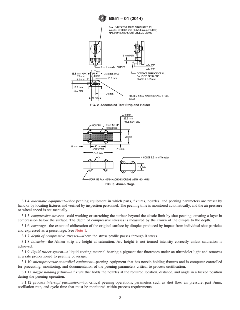
3.1.2 Almen strip holding fixture—a fixture for holding Almen strips in suitable locations that represent the position and angular
orientation of the surfaces of a part where intensity is to be determined and verified (see Fig. 2).
3.1.3 arc height—flat Almen strips, when subjected to a stream of shot moving at an adequate velocity, bending in an arc
corresponding to the amount of energy transmitted by the shot stream. The height of the curved arc measured in millimeters is the
arc height, measured by an Almen gage (see Fig. 3).
Available from Society of Automotive Engineers, 400 Commonwealth Drive, Warrendale, PA 15096.
FIG. 1 Almen Test Specimen
B851 − 04 (2014)
FIG. 2 Assembled Test Strip and Holder
FIG. 3 Almen Gage
3.1.4 automatic equipment—shot peening equipment in which parts, fixtures, nozzles, and peening parameters are preset by
hand or by locating fixtures and verified by inspection personnel. The peening time is monitored automatically, and the air pressure
or wheel speed is set manually.
3.1.5 compressive stresses—cold working or stretching the surface beyond the elastic limit by shot peening, creating a layer in
compression below the surface. The depth of compressive stresses is measured by the crown of the dimple to the depth.
3.1.6 coverage—the extent of obliteration of the original surface by dimples produced by impact from individual shot particles
and expressed as a percentage. See Note 1.
3.1.7 depth of compressive stresses—where the stress profile passes through 0 stress.
3.1.8 intensity—the Almen strip arc height at saturation. Arc height is not termed intensity correctly unless saturation is
achieved.
3.1.9 liquid tracer system—a liquid coating material bearing a pigment that fluoresces under an ultraviolet light and removes
at a rate proportioned to peening coverage.
3.1.10 microprocessor-controlled equipment—peening equipment that has nozzle holding fixtures and is computer controlled
for processing, monitoring, and documentation of the peening parameters critical to process certification.
3.1.11 nozzle holding fixture—a fixture that holds the nozzles at the required location, distance, and angle in a locked position
during the peening operation.
3.1.12 process interrupt parameters—for critical peening operations, parameters such as shot flow, air pressure, part r/min,
oscillation rate, and cycle time that must be monitored within process requirements.
B851 − 04 (2014)
3.1.13 saturation—the minimum duration of peening necessary to achieve the desired Almen intensity which, when doubled,
does not increase the Almen strip arc height by more than 10 %.
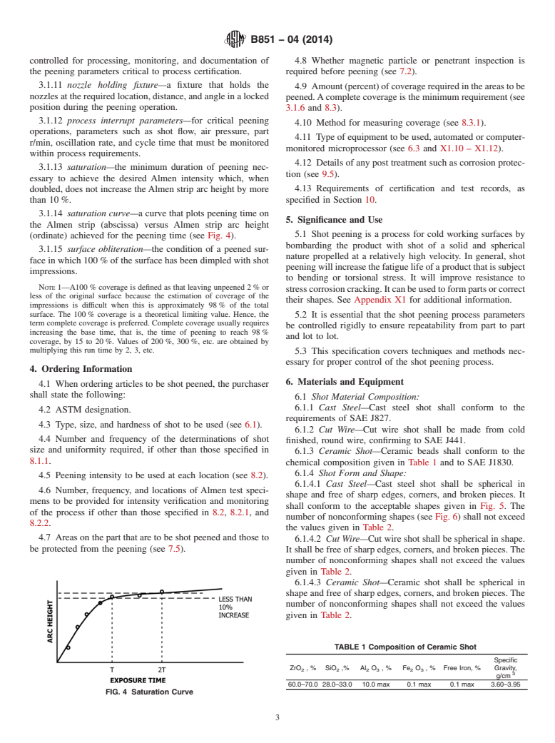
3.1.14 saturation curve—a curve that plots peening time on the Almen strip (abscissa) versus Almen strip arc height (ordinate)
achieved for the peening time (see Fig. 4).
3.1.15 surface obliteration—the condition of a peened surface in which 100 % of the surface has been dimpled with shot
impressions.
NOTE 1—A100 % coverage is defined as that leaving unpeened 2 % or less of the original surface because the estimation of coverage of the impressions
is difficult when this is approximately 98 % of the total surface. The 100 % coverage is a theoretical limiting value. Hence, the term complete coverage
is preferred. Complete coverage usually requires increasing the base time, that is, the time of peening to reach 98 % coverage, by 15 to 20 %. Values of
200 %, 300 %, etc. are obtained by multiplying this run time by 2, 3, etc.
4. Ordering Information
4.1 When ordering articles to be shot peened, the purchaser shall state the following:
4.2 ASTM designation.
4.3 Type, size, and hardness of shot to be used (see 6.1).
4.4 Number and frequency of the determinations of shot size and uniformity required, if other than those specified in 8.1.1.
4.5 Peening intensity to be used at each location (see 8.2).
4.6 Number, frequency, and locations of Almen test specimens to be provided for intensity verification and monitoring of the
process if other than those specified in 8.2, 8.2.1, and 8.2.2.
4.7 Areas on the part that are to be shot peened and those to be protected from the peening (see 7.5).
4.8 Whether magnetic particle or penetrant inspection is required before peening (see 7.2).
4.9 Amount (percent) of coverage required in the areas to be peened. A complete coverage is the minimum requirement (see
3.1.6 and 8.3).
4.10 Method for measuring coverage (see 8.3.1).
4.11 Type of equipment to be used, automated or computer-monitored microprocessor (see 6.3 and X1.10 – X1.12).
4.12 Details of any post treatment such as corrosion protection (see 9.5).
4.13 Requirements of certification and test records, as specified in Section 10.
5. Significance and Use
5.1 Shot peening is a process for cold working surfaces by bombarding the product with shot of a solid and spherical nature
propelled at a relatively high velocity. In general, shot peening will increase the fatigue life of a product that is subject to bending
or torsional stress. It will improve resistance to stress corrosion cracking. It can be used to form parts or correct their shapes. See
Appendix X1 for additional information.
5.2 It is essential that the shot peening process parameters be controlled rigidly to ensure repeatability from part to part and lot
to lot.
5.3 This specification covers techniques and methods necessary for proper control of the shot peening process.
6. Materials and Equipment
6.1 Shot Material Composition:
6.1.1 Cast Steel—Cast steel shot shall conform to the requirements of SAE J827.
6.1.2 Cut Wire—Cut wire shot shall be made from cold finished, round wire, confirming to SAE J441.
FIG. 4 Saturation Curve
B851 − 04 (2014)
6.1.3 Ceramic Shot—Ceramic beads shall conform to the chemical composition given in Table 1 and to SAE J1830.
6.1.4 Shot Form and Shape:
6.1.4.1 Cast Steel—Cast steel shot shall be spherical in shape and free of sharp edges, corners, and broken pieces. It shall
conform to the acceptable shapes given in Fig. 5. The number of nonconforming shapes (see Fig. 6) shall not exceed the values
given in Table 2.
6.1.4.2 Cut Wire—Cut wire shot shall be spherical in shape. It shall be free of sharp edges, corners, and broken pieces. The
number of nonconforming shapes shall not exceed the values given in Table 2.
6.1.4.3 Ceramic Shot—Ceramic shot shall be spherical in shape and free of sharp edges, corners, and broken pieces. The number
of nonconforming shapes shall not exceed the values given in Table 2.
6.1.5 Hardness—The hardness of the media shall exceed that of the material to be processed.
6.1.5.1 Cast Steel—Cast steel shot shall have a hardness of HR 45 to HR 55. Special hard cast steel shot shall be used on
c c
products harder than HR 50 and shall have a hardness of HR 55 to HR 65.
c c c
6.1.5.2 Cut Wire—Cut wire shot shall have a hardness equal to or greater than that given in Table 3.
6.1.5.3 Ceramic Shot—Ceramic shot shall have a minimum hardness of 560 HV (30 kgf).
6.1.6 Size:
(1) The size of the media shall be capable of producing the required intensity in the required time.
(2) If a peened surface contains a fillet, the nominal size of the shot shall not exceed one-half of the radius of the fillet.
(3) If the shot must pass through an opening, such as a slot, to reach a peened surface the nominal diameter of the shot shall
not exceed one-fourth of the width or the diameter of the opening.
6.1.6.1 Cast Steel—Cast steel shot charged into a machine shall conform to the screen requirements given in Table 4 for the
nominal size selected. When a machine has a completely new charge of cast steel shot, conditioning shall be conducted, to remove
the oxide layers on the shots, by bombarding onto a hardened steel surface for a minimum of two passes. Conditioning may not
be required if the addition to the charge already in the machine is below 25 %. If the addition of over 25 % is made to the charge,
conditioning is required.
6.1.6.2 Cut Wire—The diameter of cut wire shot charged into a machine shall conform to the requirements given in Table 4.
Cut wire shot shall conform to the requirements of length and cumulative weight given in Table 5. It is mandatory that only
preconditioned cut wire shot be used.
6.1.6.3 Ceramic Shot—Ceramic shot charged into the peening machine shall conform to the screen requirements of Table 6.
6.2 Almen Strips, Blocks, and Gages— Almen strips, blocks, and gages used shall meet the requirements of SAE J442.
6.3 Equipment—Shot peening shall be conducted in a machine that is designed for the purpose, propels shot at high speed
against the product, moves the product through the shot stream in a way that ensures complete and uniform peening, and screens
the shot continuously to remove broken or defective shot.
7. Pre-Peening Treatment
7.1 Prior Operations—Areas of parts to be shot peened shall be within dimensional requirements before peening. Except as
otherwise permitted, all heat treatment, machining, and grinding shall be completed before shot peening. All filets shall be formed,
all burrs removed, and all sharp edges and corners that require peening provided with sufficient radii prior to peening, in order to
result in complete coverage without any distortion, chipping, or rollover.
7.2 Flaw and Crack Testing—When required, magnetic particle, penetrant, ultrasonic, or other flaw or crack detection processes
shall be completed prior to peening. See Test Method E165 and Guide E709.
7.3 Corrosion and Damage—Parts shall not be peened if they show evidence of invasive corrosion or mechanical damage on
the surface.
7.4 Cleaning—Cleaning prior to peening shall be accomplished by vapor degreasing, solvent wiping, warm solvent spray, or
an acceptable water-base nonflammable product, as required, to remove all soils, scale, and coatings from the surface areas to be
peened. Se
...
Questions, Comments and Discussion
Ask us and Technical Secretary will try to provide an answer. You can facilitate discussion about the standard in here.