


ETSI GS mWT 004 V1.1.1 (2016-06)
millimetre Wave Transmission (mWT); V-band street level interference analysis
millimetre Wave Transmission (mWT); V-band street level interference analysis
DGS/mWT-004
General Information
Standards Content (Sample)
GROUP SPECIFICATION
millimetre Wave Transmission (mWT);
V-band street level interference analysis
Disclaimer
The present document has been produced and approved by the millimetre Wave Transmission (mWT) ETSI Industry
Specification Group (ISG) and represents the views of those members who participated in this ISG.
It does not necessarily represent the views of the entire ETSI membership.
2 ETSI GS mWT 004 V1.1.1 (2016-06)
Reference
DGS/mWT-004
Keywords
mWT, V-band
ETSI
650 Route des Lucioles
F-06921 Sophia Antipolis Cedex - FRANCE
Tel.: +33 4 92 94 42 00 Fax: +33 4 93 65 47 16
Siret N° 348 623 562 00017 - NAF 742 C
Association à but non lucratif enregistrée à la
Sous-Préfecture de Grasse (06) N° 7803/88
Important notice
The present document can be downloaded from:
http://www.etsi.org/standards-search
The present document may be made available in electronic versions and/or in print. The content of any electronic and/or
print versions of the present document shall not be modified without the prior written authorization of ETSI. In case of any
existing or perceived difference in contents between such versions and/or in print, the only prevailing document is the
print of the Portable Document Format (PDF) version kept on a specific network drive within ETSI Secretariat.
Users of the present document should be aware that the document may be subject to revision or change of status.
Information on the current status of this and other ETSI documents is available at
https://portal.etsi.org/TB/ETSIDeliverableStatus.aspx
If you find errors in the present document, please send your comment to one of the following services:
https://portal.etsi.org/People/CommiteeSupportStaff.aspx
Copyright Notification
No part may be reproduced or utilized in any form or by any means, electronic or mechanical, including photocopying
and microfilm except as authorized by written permission of ETSI.
The content of the PDF version shall not be modified without the written authorization of ETSI.
The copyright and the foregoing restriction extend to reproduction in all media.
© European Telecommunications Standards Institute 2016.
All rights reserved.
TM TM TM
DECT , PLUGTESTS , UMTS and the ETSI logo are Trade Marks of ETSI registered for the benefit of its Members.
TM
3GPP and LTE™ are Trade Marks of ETSI registered for the benefit of its Members and
of the 3GPP Organizational Partners.
GSM® and the GSM logo are Trade Marks registered and owned by the GSM Association.
ETSI
3 ETSI GS mWT 004 V1.1.1 (2016-06)
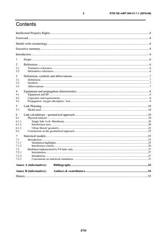
Contents
Intellectual Property Rights . 4
Foreword . 4
Modal verbs terminology . 4
Executive summary . 4
Introduction . 4
1 Scope . 6
2 References . 6
2.1 Normative references . 6
2.2 Informative references . 6
3 Definitions, symbols and abbreviations . 7
3.1 Definitions . 7
3.2 Symbols . 7
3.3 Abbreviations . 7
4 Equipment and propagation characteristics . 8
4.1 Equipment and RF . 8
4.2 Capacities and requirements . 8
4.3 Propagation: oxygen absorption - loss. 9
5 Link Planning . 10
5.1 Model used . 10
6 Link calculations - geometrical approach. 10
6.1 Physical analysis . 10
6.1.1 Single link- LoS -Mainbeam . 10
6.1.2 Interference area . 20
6.1.3 Urban Streets' geometry . 22
6.2 Conclusions on the geometrical approach . 25
7 Statistical models . 25
7.1 Introduction . 25
7.1.1 Simulation highlights . 25
7.1.2 Interference criteria . 26
7.2 Backhaul implemented by FS links only . 27
7.2.1 Introduction. 27
7.2.2 Simulations . 27
7.2.3 Conclusions on statistical simulation . 31
Annex A (informative): Bibliography . 33
Annex B (informative): Authors & contributors . 34
History . 35
ETSI
4 ETSI GS mWT 004 V1.1.1 (2016-06)
Intellectual Property Rights
IPRs essential or potentially essential to the present document may have been declared to ETSI. The information
pertaining to these essential IPRs, if any, is publicly available for ETSI members and non-members, and can be found
in ETSI SR 000 314: "Intellectual Property Rights (IPRs); Essential, or potentially Essential, IPRs notified to ETSI in
respect of ETSI standards", which is available from the ETSI Secretariat. Latest updates are available on the ETSI Web
server (https://ipr.etsi.org/).
Pursuant to the ETSI IPR Policy, no investigation, including IPR searches, has been carried out by ETSI. No
guarantee can be given as to the existence of other IPRs not referenced in ETSI SR 000 314 (or the updates on the
ETSI Web server) which are, or may be, or may become, essential to the present document.
Foreword
This Group Specification (GS) has been produced by ETSI Industry Specification Group (ISG) millimetre Wave
Transmission (mWT).
Modal verbs terminology
In the present document "shall", "shall not", "should", "should not", "may", "need not", "will", "will not", "can" and
"cannot" are to be interpreted as described in clause 3.2 of the ETSI Drafting Rules (Verbal forms for the expression of
provisions).
"must" and "must not" are NOT allowed in ETSI deliverables except when used in direct citation.
Executive summary
The present document is related to the evaluation of interference that is expected to affect Fixed Service (FS)
links, operating at street level in Radio Frequency (RF) band 57 - 66 GHz, (so called V-band), which is widely
subject to unlicensed or light licensed regimes for part below 64 GHz.
The interference level in such conditions is a function of network density, equipment and antenna characteristics,
available Bandwidth (BW). ®
In particular, the probabilistic analysis made with the SEAMCAT tool, and the equipment and antennas designed
according to the ETSI EN 302 217 multipart standard [i.1] and [i.2], show that, provided that a limited number of
channels (5 to 10) are available, with limited channel BW ( 200 to 400 MHz), the operations of very high density
networks with link density of up to about 200 links / km , to transmit high transmission capacities (in the order of
1 GHz/s per channel), are achieving acceptable confidence levels of operations (less than 2 % interference
probability). Antenna class 2 RPE is proven to be already enough effective. ®
NOTE: SEAMCAT is the trade name of a product supplied by the European Communications Office (ECO)
This information is given for the convenience of users of the present document and does not constitute an
endorsement by ETSI of the product named. Equivalent products may be used if they can be shown to
lead to the same results.
Introduction
The specific characteristics of the V-band, concerning propagation and licensing, implies further analysis for
understanding the condition of usage in specified environments.
While the high propagation loss due to oxygen absorption is expected to simplify frequency reuse and interference
related impairments, the widespread adoption of licensing regimes, not generally link-by-link based, implies that it
is not generally possible to implement an interference control mechanism based on the knowledge of the
characteristics of links in a common geographic area.
ETSI
5 ETSI GS mWT 004 V1.1.1 (2016-06)
For same reasons, even in the case a block license is assigned, the licensee can experience difficulties in
undertaking this activity, due to the difficulty of knowing if other services, apart from FS, are also using the band
in some locations. In any case, the user of the block needs to evaluate, in relation with the block size, how much
the block can be used in term of exploitable link density.
The present document is intended to clarify these issues and aims to provide some general considerations and
guidance.
ETSI
6 ETSI GS mWT 004 V1.1.1 (2016-06)
1 Scope
The present document examines the application of radio links in the V-band frequencies, in urban applications,
with special regard to interference issues, taking into account equipment characteristics, propagation issues and
expected requirements.
Wherever possible, punctual and statistical analyses are performed and applicability of calculation methods is
investigated.
The purpose of the present document is to investigate the feasibility of using unlicensed band by analysing
interference levels in co-channels and adjacent channels in dense deployment of Point to Point (PP) radio at the
street level, taking into considerations
• equipment characteristics,
• capacities and BW requirements,
• standards,
• available channels,
• antennas,
• available standards and propagation:
- oxygen absorption;
- loss and modelling.
2 References
2.1 Normative references
References are either specific (identified by date of publication and/or edition number or version number) or
non-specific. For specific references, only the cited version applies. For non-specific references, the latest version
of the referenced document (including any amendments) applies.
Referenced documents which are not found to be publicly available in the expected location might be found at
http://docbox.etsi.org/Reference.
NOTE: While any hyperlinks included in this clause were valid at the time of publication, ETSI cannot
guarantee their long term validity.
The following referenced documents are necessary for the application of the present document.
Not applicable.
2.2 Informative references
References are either specific (identified by date of publication and/or edition number or version number) or
non-specific. For specific references, only the cited version applies. For non-specific references, the latest version
of the referenced document (including any amendments) applies.
NOTE: While any hyperlinks included in this clause were valid at the time of publication, ETSI cannot
guarantee their long term validity.
ETSI
7 ETSI GS mWT 004 V1.1.1 (2016-06)
The following referenced documents are not necessary for the application of the present document but they assist
the user with regard to a particular subject area.
[i.1] ETSI EN 302 217-3: "Fixed Radio Systems; Characteristics and requirements for point-to-point
equipment and antennas; Part 3: Equipment operating in frequency bands where both frequency
coordinated or uncoordinated deployment might be applied; Harmonized EN covering the essential
requirements of article 3.2 of the R&TTE Directive".
[i.2] ETSI EN 302 217-4-2 (V1.4.1): "Fixed Radio Systems; Characteristics and requirements for
point-to-point equipment and antennas; Part 4-2: Antennas; Harmonized EN covering the essential
requirements of article 3.2 of the R&TTE Directive".
[i.3] ECC Report 20: "Methodology to determine the density of Fixed Service".
[i.4] Recommendation ITU-R F.699: "Reference radiation patterns for line-of-sight radio-relay system
antennas for use in coordination studies and interference assessment in the frequency range from
1 GHz to about 70 GHz".
[i.5] Recommendation ITU-R P.676: "Attenuation by atmospheric gases".
[i.6] ECC Report 114: "Compatibility studies between multiple gigabit wireless systems in frequency
range 57-66 GHz and other services and systems (except its in 63-64 GHz)".
[i.7] Recommendation ITU-T G.826: "End-to-end error performance parameters and objectives for
international, constant bit-rate digital paths and connections".
[i.8] ETSI EN 302 217-4-1: "Fixed Radio Systems; Characteristics and requirements for point-to-point
equipment and antennas; Part 4-1: System-dependent requirements for antennas". ®
[i.9] SEAMCAT Spectrum Engineering Advanced Monte Carlo Analysis.
NOTE: Available at: http://www.seamcat.org/.
[i.10] ITU-R Recommendation P.452: "Prediction procedure for the evaluation of interference between
stations on the surface of the Earth at frequencies above about 0.1 GHz".
3 Definitions, symbols and abbreviations
3.1 Definitions
For the purposes of the present document, the following terms and definitions apply:
Void.
3.2 Symbols
For the purposes of the present document, the following symbols apply:
C/I Carrier-to-interference Ratio
I/N Interference-To-Noise Ratio
P.Out Output Power
Rx Receiver
Tx Transmitter
3.3 Abbreviations
For the purposes of the present document, the following abbreviations apply:
ATPC Adaptive Transmitter Power Control
BW BandWidth
ETSI
8 ETSI GS mWT 004 V1.1.1 (2016-06)
C Carrier
dBi dB relative to an isotropic radiator
DFS Dynamic Frequency Selection
FR Frequency Range
FS Fixed Service
G antenna Gain
I Interferer
LoS Line of Sight
N Noise
PP Point-to-Point
RF Radio Frequency
RPE Reference Pattern Envelope
RSL Received Signal Level
thr threshold
QAM Quadrature Amplitude Modulation
QPSK Quadrature Phase Shift Keying
4 Equipment and propagation characteristics
4.1 Equipment and RF
Link calculation has been executed starting from different equipment characteristics with different modulation
schemes.
The following assumptions were made, based on ETSI EN 302 217-3 [i.1] for equipment in the 64 - 66 RF band:
Transmitter (Tx) power = +10 dBm
Quadrature Phase Shift Keying (QPSK), 16 Quadrature Amplitude Modulation (QAM) and 64QAM modulation
schemes are considered.
Receiver (Rx) threshold: 4 QPSK: -65,5 dBm
16QAM: -58,5 dBm
64QAM: -52,5 dBm
Carrier-to-interference Ratio (C/I) (1 dB degradation): 4 QPSK = 24 dB
16QAM = 31 dB
64QAM = 38 dB
C/I (3 dB degradation): 4 QPSK = 15 dB
64QAM = 29 dB
Channel size: 200 MHz Channels have been used, obtained by joining 4 consecutive 50 MHz basic channels.
4.2 Capacities and requirements
Modulation schemes adopted in the examples are QPSK, 16QAM and 64QAM, corresponding to capacities in the
order of 300 Mbit/s to 1 Gbit/s.
Parameters and Objectives:
• Availability has only been accounted for two values: 99,9 %, 99,99 %.
Values in this range are commonly used when unlicensed spectrum use is considered, and are coherent with the
general approach of objectives' apportionment expressed by the ITU-T (e.g. Recommendation ITU-T G.826 [i.7])
ETSI
9 ETSI GS mWT 004 V1.1.1 (2016-06)
for end-to-end paths, where less relaxed objectives are allowed to the edge (terminating) sections in comparison
with the transit portions, where much higher requirements are needed to allow for proper end-to-end figures.
Rain rate: Three values for rain rate have been used from low to moderate: 30 mm/h, 42 mm/h, 60 mm/h.
• Antennas:
- Antennas - RPE have been calculated according to Recommendation ITU-R F.699 [i.4] and ETSI
EN 302 217-4-2 [i.2].
- Antenna gain: Two gain values have been considered: 38 dBi; 32 dBi.
In order to be relatively close to real devices, characteristics in the main lobe have been done in accordance with
Recommendation ITU-R F.699 [i.4], while Reference Pattern Envelope (RPE) outside the main lobe has been obtained
as a realistic compromise between ITU-R and ETSI, since ETSI does not provide values for mainlobe.
An example of the RPE derivation is shown in figure 4.2.1 (38 dBi, ETSI EN 302 217-4-2 [i.2] FR7 class 3).
Figure 4.2.1: RPE derivation
4.3 Propagation: oxygen absorption - loss
Effect of gas absorption can be found in Recommendation ITU-R P.676 [i.5].
Figures 4.3.1 and 4.3.2 show current values according to version in force (Recommendation ITU-R P.676-10) [i.5].
Figure 4.3.1: total attenuation
ETSI
10 ETSI GS mWT 004 V1.1.1 (2016-06)
Figure 4.3.2: attenuation
5 Link Planning
5.1 Model used
Initial calculations have been performed based on a single link in Line of Sight (LoS) condition:
- Analysis of expected hop length has been performed.
- Analysis of interference areas in same conditions are reported.
6 Link calculations - geometrical approach
6.1 Physical analysis
6.1.1 Single link- LoS -Mainbeam
Effect of frequency /Effect of rain
The maximum hop length corresponding to 99,9 % of availability have been computed for QPSK, 16QAM,
64QAM with a 32 dBi and 38 dBi antennas, at three rain rates as above.
Three different oxygen attenuations have been used (4,1 / 12,8 / 14,6 dB/km) representing different frequency (58,
61,5 and 65 GHz) of the considered V band.
Related diagrams are shown in figures 6.1.1.1 and 6.1.1.2.
Same results are shown with 99,99 % availability (figures 6.1.1.3 and 6.1.1.4).
ETSI
11 ETSI GS mWT 004 V1.1.1 (2016-06)
Necessary Fade Margin vs Hop Length
0 100 200 300 400 500 600 700 800 900 1000
Max length (km)
Avail.FM (Case 1): 200 MHz Ch . - QPSK - TX: 4 d Bm - An t.: 32/32 d B -Losses: 0 dB - Th r.: -65.5 d Bm
Avail.FM (Case 2): 200 MHz Ch. - 16 QAM - TX: 4 dBm - Ant.: 32/32 dB -Losses: 0 dB - Thr.: -58.5 dBm
Avail.FM (Case 3): 200 MHz Ch. - 64 QAM - TX: 4 dBm - Ant.: 32/32 dB -Losses: 0 dB - Thr.: -52.5 dBm
Nec.FM (Case 1) - Freq.: 65 GHz - Rain: 30 mm/h - Pol.: V - Obj.: 99.9 % - Gas Attenuation : 4.1 dB/km
Nec.FM (Case 2) - Freq.: 65 GHz - Rain: 42 mm/h - Pol.: V - Obj.: 99.9 % - Gas Attenuation : 4.1 dB/km
Nec.FM (Case 3) - Freq.: 65 GHz - Rain: 60 mm/h - Pol.: V - Obj.: 99.9 % - Gas Attenuation : 4.1 dB/km
Necessary Fade Margin vs Hop Length
0 100 200 300 400 500 600 700 800 900 1000
Max length (km)
Avail.FM (Case 1): 200 MHz Ch . - QPSK - TX: 4 d Bm - An t.: 32/32 d B -Losses: 0 dB - Th r.: -65.5 d Bm
Avail.FM (Case 2): 200 MHz Ch. - 16 QAM - TX: 4 dBm - Ant.: 32/32 dB -Losses: 0 dB - Thr.: -58.5 dBm
Avail.FM (Case 3): 200 MHz Ch. - 64 QAM - TX: 4 dBm - Ant.: 32/32 dB -Losses: 0 dB - Thr.: -52.5 dBm
Nec.FM (Case 1) - Freq.: 58 GHz - Rain: 30 mm/h - Pol.: V - Obj.: 99.9 % - Gas Attenuation : 12.8 dB/km
Nec.FM (Case 2) - Freq.: 58 GHz - Rain: 42 mm/h - Pol.: V - Obj.: 99.9 % - Gas Attenuation : 12.8 dB/km
Nec.FM (Case 3) - Freq.: 58 GHz - Rain: 60 mm/h - Pol.: V - Obj.: 99.9 % - Gas Attenuation : 12.8 dB/km
ETSI
Fade Margin (dB) Fade Margin (dB)
12 ETSI GS mWT 004 V1.1.1 (2016-06)
Necessary Fade Margin vs Hop Length
0 100 200 300 400 500 600 700 800 900 1000
Max length (km)
Avail.FM (Case 1): 200 MHz Ch . - QPSK - TX: 4 d Bm - An t.: 32/32 d B -Losses: 0 dB - Th r.: -65.5 d Bm
Avail.FM (Case 2): 200 MHz Ch. - 16 QAM - TX: 4 dBm - Ant.: 32/32 dB -Losses: 0 dB - Thr.: -58.5 dBm
Avail.FM (Case 3): 200 MHz Ch. - 64 QAM - TX: 4 dBm - Ant.: 32/32 dB -Losses: 0 dB - Thr.: -52.5 dBm
Nec.FM (Case 1) - Freq.: 61.5 GHz - Rain: 30 mm/h - Pol.: V - Obj.: 99.9 % - Gas Attenuation : 14.6 dB/km
Nec.FM (Case 2) - Freq.: 61.5 GHz - Rain: 42 mm/h - Pol.: V - Obj.: 99.9 % - Gas Attenuation : 14.6 dB/km
Nec.FM (Case 3) - Freq.: 61.5 GHz - Rain: 60 mm/h - Pol.: V - Obj.: 99.9 % - Gas Attenuation : 14.6 dB/km
-
Figure 6.1.1.1: Maximum hop length, avail 99,9 %, 32 dBi antenna, QPSK to 64QAM
ETSI
Fade Margin (dB)
13 ETSI GS mWT 004 V1.1.1 (2016-06)
Necessary Fade Margin vs Hop Length
0 200 400 600 800 1000 1200 1400 1600 1800 2000
Max length (km)
Avail.FM (Case 1): 200 MHz Ch. - QPSK - TX: 10 dBm - Ant.: 38/38 dB -Losses: 0 dB - Thr.: -65.5 dBm
Avail.FM (Case 2): 200 MHz Ch. - 16 QAM - TX: 10 dBm - Ant.: 38/38 dB -Losses: 0 dB - Thr.: -58.5 dBm
Avail.FM (Case 3): 200 MHz Ch. - 64 QAM - TX: 10 dBm - Ant.: 38/38 dB -Losses: 0 dB - Thr.: -52.5 dBm
Nec.FM (Case 1) - Freq.: 65 GHz - Rain: 30 mm/h - Pol.: V - Obj.: 99.9 % - Gas Attenuation : 4.1 dB/km
Nec.FM (Case 2) - Freq.: 65 GHz - Rain: 42 mm/h - Pol.: V - Obj.: 99.9 % - Gas Attenuation : 4.1 dB/km
Nec.FM (Case 3) - Freq.: 65 GHz - Rain: 60 mm/h - Pol.: V - Obj.: 99.9 % - Gas Attenuation : 4.1 dB/km
Necessary Fade Margin vs Hop Length
0 200 400 600 800 1000 1200 1400 1600 1800 2000
Max length (km)
Avail.FM (Case 1): 200 MHz Ch. - QPSK - TX: 10 dBm - Ant.: 38/38 dB -Losses: 0 dB - Thr.: -65.5 dBm
Avail.FM (Case 2): 200 MHz Ch. - 16 QAM - TX: 10 dBm - Ant.: 38/38 dB -Losses: 0 dB - Thr.: -58.5 dBm
Avail.FM (Case 3): 200 MHz Ch. - 64 QAM - TX: 10 dBm - Ant.: 38/38 dB -Losses: 0 dB - Thr.: -52.5 dBm
Nec.FM (Case 1) - Freq.: 58 GHz - Rain: 30 mm/h - Pol.: V - Obj.: 99.9 % - Gas Attenuation : 12.8 dB/km
Nec.FM (Case 2) - Freq.: 58 GHz - Rain: 42 mm/h - Pol.: V - Obj.: 99.9 % - Gas Attenuation : 12.8 dB/km
Nec.FM (Case 3) - Freq.: 58 GHz - Rain: 60 mm/h - Pol.: V - Obj.: 99.9 % - Gas Attenuation : 12.8 dB/km
ETSI
Fade Margin (dB)
Fade Margin (dB)
14 ETSI GS mWT 004 V1.1.1 (2016-06)
Necessary Fade Margin vs Hop Length
0 200 400 600 800 1000 1200 1400 1600 1800 2000
Max length (km)
Avail.FM (Case 1): 200 MHz Ch. - QPSK - TX: 10 dBm - Ant.: 38/38 dB -Losses: 0 dB - Thr.: -65.5 dBm
Avail.FM (Case 2): 200 MHz Ch. - 16 QAM - TX: 10 dBm - Ant.: 38/38 dB -Losses: 0 dB - Thr.: -58.5 dBm
Avail.FM (Case 3): 200 MHz Ch. - 64 QAM - TX: 10 dBm - Ant
...
Questions, Comments and Discussion
Ask us and Technical Secretary will try to provide an answer. You can facilitate discussion about the standard in here.
Loading comments...