


ETSI GS mWT 006 V1.1.1 (2015-12)
millimetre Wave Transmission (mWT); Analysis of antennas for millimetre wave transmission
millimetre Wave Transmission (mWT); Analysis of antennas for millimetre wave transmission
DGS/mWT-006
General Information
Standards Content (Sample)
GROUP SPECIFICATION
millimetre Wave Transmission (mWT);
Analysis of antennas for millimetre wave transmission
Disclaimer
This document has been produced and approved by the millimetre Wave Transmission (mWT) ETSI Industry Specification
Group (ISG) and represents the views of those members who participated in this ISG.
It does not necessarily represent the views of the entire ETSI membership.
2 ETSI GS mWT 006 V1.1.1 (2015-12)
Reference
DGS/mWT-006
Keywords
antenna, application, millimetre wave, mWT, use
case
ETSI
650 Route des Lucioles
F-06921 Sophia Antipolis Cedex - FRANCE
Tel.: +33 4 92 94 42 00 Fax: +33 4 93 65 47 16
Siret N° 348 623 562 00017 - NAF 742 C
Association à but non lucratif enregistrée à la
Sous-Préfecture de Grasse (06) N° 7803/88
Important notice
The present document can be downloaded from:
http://www.etsi.org/standards-search
The present document may be made available in electronic versions and/or in print. The content of any electronic and/or
print versions of the present document shall not be modified without the prior written authorization of ETSI. In case of any
existing or perceived difference in contents between such versions and/or in print, the only prevailing document is the
print of the Portable Document Format (PDF) version kept on a specific network drive within ETSI Secretariat.
Users of the present document should be aware that the document may be subject to revision or change of status.
Information on the current status of this and other ETSI documents is available at
http://portal.etsi.org/tb/status/status.asp
If you find errors in the present document, please send your comment to one of the following services:
https://portal.etsi.org/People/CommiteeSupportStaff.aspx
Copyright Notification
No part may be reproduced or utilized in any form or by any means, electronic or mechanical, including photocopying
and microfilm except as authorized by written permission of ETSI.
The content of the PDF version shall not be modified without the written authorization of ETSI.
The copyright and the foregoing restriction extend to reproduction in all media.
© European Telecommunications Standards Institute 2015.
All rights reserved.
TM TM TM
DECT , PLUGTESTS , UMTS and the ETSI logo are Trade Marks of ETSI registered for the benefit of its Members.
TM
3GPP and LTE™ are Trade Marks of ETSI registered for the benefit of its Members and
of the 3GPP Organizational Partners.
GSM® and the GSM logo are Trade Marks registered and owned by the GSM Association.
ETSI
3 ETSI GS mWT 006 V1.1.1 (2015-12)
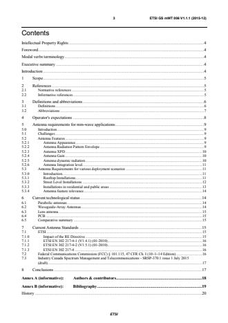
Contents
Intellectual Property Rights . 4
Foreword . 4
Modal verbs terminology . 4
Executive summary . 4
Introduction . 4
1 Scope . 5
2 References . 5
2.1 Normative references . 5
2.2 Informative references . 5
3 Definitions and abbreviations . 6
3.1 Definitions . 6
3.2 Abbreviations . 7
4 Operator's expectations . 8
5 Antenna requirements for mm-wave applications . 9
5.0 Introduction . 9
5.1 Challenges . 9
5.2 Antenna Features . 9
5.2.1 Antenna Appearance . 9
5.2.2 Antenna Radiation Pattern Envelope . 9
5.2.3 Antenna XPD . 10
5.2.4 Antenna Gain . 10
5.2.5 Antenna dynamic radiation . 10
5.2.6 Antenna Integration level . 11
5.3 Antenna Requirements for various deployment scenarios . 11
5.3.0 Introduction. 11
5.3.1 Rooftop Installations . 11
5.3.2 Street Level Installations . 12
5.3.3 Installations in residential and public areas . 13
5.3.4 Antenna feature relevance. 14
6 Current technological status . 14
6.1 Parabolic antennas . 14
6.2 Waveguide-Array Antennas . 14
6.3 Lens antenna . 15
6.4 PCB . 15
6.5 Comparative summary . 15
7 Current Antenna Standards . . 15
7.1 ETSI . 15
7.1.0 Impact of the RE Directive . 15
7.1.1 ETSI EN 302 217-4-1 (V1.4.1) (01-2010) . 16
7.1.2 ETSI EN 302 217-4-2 (V1.5.1) (01-2010) . 16
7.1.3 ETSI EN 302 217-4 . 16
7.2 Federal Communications Commission (FCC) § 101.115, 47 CFR Ch. I (10–1–14 Edition) . 16
7.3 Industry Canada Spectrum Management and Telecommunications - SRSP-370.1 issue 1 July 2015
(draft) . 17
8 Conclusions . 17
Annex A (informative): Authors & contributors . 18
Annex B (informative): Bibliography . 19
History . 20
ETSI
4 ETSI GS mWT 006 V1.1.1 (2015-12)
Intellectual Property Rights
IPRs essential or potentially essential to the present document may have been declared to ETSI. The information
pertaining to these essential IPRs, if any, is publicly available for ETSI members and non-members, and can be found
in ETSI SR 000 314: "Intellectual Property Rights (IPRs); Essential, or potentially Essential, IPRs notified to ETSI in
respect of ETSI standards", which is available from the ETSI Secretariat. Latest updates are available on the ETSI Web
server (http://ipr.etsi.org).
Pursuant to the ETSI IPR Policy, no investigation, including IPR searches, has been carried out by ETSI. No guarantee
can be given as to the existence of other IPRs not referenced in ETSI SR 000 314 (or the updates on the ETSI Web
server) which are, or may be, or may become, essential to the present document.
Foreword
This Group Specification (GS) has been produced by ETSI Industry Specification Group (ISG) millimetre Wave
Transmission (mWT).
Modal verbs terminology
In the present document "shall", "shall not", "should", "should not", "may", "need not", "will", "will not", "can" and
"cannot" are to be interpreted as described in clause 3.2 of the ETSI Drafting Rules (Verbal forms for the expression of
provisions).
"must" and "must not" are NOT allowed in ETSI deliverables except when used in direct citation.
Executive summary
On the basis of selected applications and use cases in the millimetre wave band, especially in the V- and E-bands, and
based on operators' expectations as defined in ETSI GS mWT 002 [i.1], appropriate antennas requirements have been
identified. Several deployment scenarios as well as the relevance of antenna features.
A current technology review and a status review of existing standards put in perspective the challenges that the industry
is facing with those new requirements.
Introduction
The number and quality of services that can be offered in a given band highly depend on the efficient use of spectrum
which is closely related to the performance of the antennas. Antenna functions are key when it comes to effective
spectrum management and consequent service availability.
The present document reflects a common agreement on how best to make spectrum available for the different use cases
in order to avoid delays, confusion, and missed opportunities.
Antenna requirements for different mm-wave applications and use cases vary significantly.
The variety of antenna options and requirements are of great relevance for different applications and use cases. While
strict licencing and tough antenna quality requirements may be the best solution in one application, another use case
may call for a more self-organized deployment with antenna features that help avoid interference.
ETSI
5 ETSI GS mWT 006 V1.1.1 (2015-12)
1 Scope
The purpose of the present document is to provide an analysis on antennas to be used for millimetre wave transmission
covering:
• Operators' key expectations.
• Use cases (described in ETSI GS mWT 002 [i.1]) and related point to point and multipoint millimetre-wave
(V-band and E-band) antenna requirements.
• Review of the current technological and regulatory status.
• Definition of terminology.
2 References
2.1 Normative references
References are either specific (identified by date of publication and/or edition number or version number) or
non-specific. For specific references, only the cited version applies. For non-specific references, the latest version of the
reference document (including any amendments) applies.
Referenced documents which are not found to be publicly available in the expected location might be found at
http://docbox.etsi.org/Reference.
NOTE: While any hyperlinks included in this clause were valid at the time of publication, ETSI cannot guarantee
their long term validity.
The following referenced documents are necessary for the application of the present document.
Not applicable.
2.2 Informative references
References are either specific (identified by date of publication and/or edition number or version number) or
non-specific. For specific references, only the cited version applies. For non-specific references, the latest version of the
reference document (including any amendments) applies.
NOTE: While any hyperlinks included in this clause were valid at the time of publication, ETSI cannot guarantee
their long term validity.
The following referenced documents are not necessary for the application of the present document but they assist the
user with regard to a particular subject area.
[i.1] ETSI GS mWT 002: "millimetre Wave Transmission (mWT); Applications and use cases of
millimetre wave transmission".
[i.2] ETSI White Paper No.9: "Overview on V-band and E-band worldwide regulations".
[i.3] Directive 2014/53/EU of the European Parliament and of the Council of 16 April 2014 on the
harmonisation of the laws of the Member States relating to the making available on the market of
radio equipment and repealing Directive 1999/5/EC.
[i.4] ETSI EN 302 217-4-2 (V1.5.1) (01-2010): "Fixed Radio Systems; Characteristics and
requirements for point-to-point equipment and antennas; Part 4-2: Antennas; Harmonized EN
covering the essential requirements of article 3.2 of the R&TTE Directive".
[i.5] Federal Communications Commission (FCC) § 101.115, 47 CFR Ch. I (10-1-14 Edition).
[i.6] Industry Canada Spectrum Management and Telecommunications - SRSP-370.1 issue 1 July 2015
(draft).
NOTE: At the time of publication, this document is in draft status.
ETSI
6 ETSI GS mWT 006 V1.1.1 (2015-12)
[i.7] D.M. Pozar: "Microwave Engineering", 4th edition, Wiley, 2012.
[i.8] ETSI EN 302 217-4-1: "Fixed Radio Systems; Characteristics and requirements for point-to-point
equipment and antennas; Part 4-1: System-dependent requirements for antennas".
[i.9] ETSI EN 302 217-4: "Fixed Radio Systems; Characteristics and requirements for point-to-point
equipment and antennas; Part 4: Antennas".
[i.10] Directive 1999/5/EC of the European Parliament and of the Council of 9 March 1999 on radio
equipment and telecommunications terminal equipment and the mutual recognition of their
conformity (R&TTE Directive).
[i.11] ETSI EN 302 217-1: "Fixed Radio Systems; Characteristics and requirements for point-to-point
equipment and antennas; Part 1: Overview, common characteristics and system-dependent
requirements".
[i.12] ETSI EN 302 217-2: "Fixed Radio Systems; Characteristics and requirements for point-to-point
equipment and antennas; Part 2: Digital systems operating in frequency bands from 1,3 GHz to 86
GHz; Harmonised Standard covering the essential requirements of article 3.2 of the
Directive 2014/53/EU".
[i.13] ETSI EN 302 217-3: "Fixed Radio Systems; Characteristics and requirements for point-to-point
equipment and antennas; Part 3: Harmonized EN covering essential requirements of Article 3.2 of
R&TTE Directive for equipment operating in frequency bands where no frequency co-ordination
is applied".
3 Definitions and abbreviations
3.1 Definitions
For the purposes of the present document, the following terms and definitions apply:
active antenna: antenna, where the electromagnetic signal can be amplified or processed electronically before radiation
or after reception or both
NOTE: This antenna includes active components.
Adaptive Antenna System (AAS): array of antennas and associated signal processing that together is able to change its
antenna radiation pattern dynamically to adjust to noise environment, interference and multipath
adaptive nulling: functionality of an antenna system, associated with signal processing, where the direction of a null
(or more than one null) of its radiation pattern can be changed dynamically to adjust to noise environment, interference
and multipath
NOTE: A null is the direction where local minima exist in a radiation pattern due the destructive interference of
the wave fronts.
beam forming: functionality of an antenna system, where the amplitude and phase of radiating aperture of the antenna
system is optimized through different techniques to achieve a desired shaped radiation pattern
beam steering: functionality of an antenna system, which allows the change in the direction of the main lobe of its
radiation pattern
NOTE 1: The change in direction of the main lobe could be in more than one plane.
NOTE 2: The functionality of beam steering is achieved electrically or electro-mechanically.
dedicated antenna: antenna specifically designed for being attached to the radio equipment (i.e. with special
mechanical fixing to the antenna port of the specific radio supplied), but can be separated from the equipment (typically
for transport purpose) using normal tools
NOTE: For the design and testing of an accurate and precise interface between radio and antenna, intimate details
of the mating parts are required. Dedicated antennas are specifically designed for specific radios and
therefore ensure mechanical integrity, significantly reducing the risk for RF leakage and moisture ingress.
ETSI
7 ETSI GS mWT 006 V1.1.1 (2015-12)
dynamic auto-alignment: system where there is active compensation for movement of the microwave antenna support
structure such that point to point link integrity is maintained up to the rated operational specification of the antenna,
typically 0,3 times the 3 dB beamwidth
installation alignment: optical or electronical system used to manually or automatically align the two antenna main
beams during initial installation of the link
Figure 1
integral/integrated antenna: antenna which is declared as part of the radio equipment by the supplier is not physically
separable from the equipment, unless it is returned to the manufacturer premises
NOTE: With integral/integrated antennas the designer owns all details of the interface between radio and antenna
which allows for accurate and precise interface design. In addition the interface is enclosed by the radio
housing. This drastically reduces the severe risk of moisture ingress and RF leakage.
phased array antennas: array of antennas or elements, which are simultaneously fed, and whose relative phase can be
varied to change the pointing direction and beam shape of the main lobe of the array antenna radiation pattern during
operation
NOTE: Main lobe or major lobe or beam is the radiation lobe containing the direction of maximum radiation. By
setting the relative power levels between the phased array elements, the beamwidth of the main lobe and
its sidelobe structure may be further controlled.
selectable beam antennas: antennas using time delays between arrays rather than phase shifters between arrays to steer
the main beam
NOTE 1: This approach can be implemented using by either selectable line lengths or by selecting different launch
configurations (e.g. different selected feeds or electronically reconfigurable reflectors) within a
microwave-optic beamformer (e.g. lens/reflector systems).
NOTE 2: Selectable beam antennas may replace fixed beam antennas without the need to change the radio unit,
however some extra control will be required to select the appropriate beam and possibly allow for
reconfiguration. They are available with planar, cylindrical and spherical sector apertures and in their
microwave optic form may allow omni or floodlight beam operation in their zero power default modes.
stand-alone antenna (ETSI definition): antenna designed independently from the fixed radio equipment, by the same
or a different supplier and connected to the radio equipment in the field through standard cables or waveguides
3.2 Abbreviations
For the purposes of the present document, the following abbreviations apply:
3GPP Third Generation Partnership Project
5G Fifth Generation of Mobile Networks
CFR Code of Federal Regulations
CPD co-Polar Discrimination
CPRI Common Public Radio Interface
EC European Commission
EIRP Effective Isotropic Radiated Power
EU European Union
FCC: Federal Commission for Communications
IMT-Advanced International Mobile Telecommunications-Advanced
ETSI
8 ETSI GS mWT 006 V1.1.1 (2015-12)
LOS Line Of Sight
LTE Long Term Evolution
nLOS near Line Of Sight
NLOS Non Line Of Sight
OBSAI Open Base Station Architecture Initiative
ORI Open Radio equipment Interface
PCB Printed Circuit Board
PtMP Point to MultiPoint
PtP Point to Point
QoS Quality of Service
RE Radio Equipment
RF Radio Frequency
RPE: Radiation Pattern Envelope
SRSP Standard Radio System Plans
TCO Total Cost of Ownership
TV TeleVision
WI: WorkItem
XPD cross-Polar Discrimination
4 Operator's expectations
As detailed in the ETSI GS mWT 002 [i.1] and summarized in clause 6, multiple use cases have been identified for V-
and E-band equipment. The key expectations of the operators for antennas have nevertheless some common points and
some specific requirements per use case as well.
Ease of installation: It is expected that the installation and specifically the antenna alignment should not take more
than a few minutes. This could be a real challenge with large gain parabolic antennas, for instance a 2ft E-Band antenna
with a typical beamwidth of less than 0,5°. Besides, unskilled technicians could be in charge of antenna installation of
street level equipment with basic link testing equipment. It can be anticipated that the initial alignment might not be
precise enough.
In both cases, namely a macro-layer high gain/narrow beamwidth antenna and a street level equipment, an auto-
alignment function would be preferred.
Regulatory constraints: The compatibility of the technical requirements defined by the existing standards, issued by
ETSI or FCC, and the antenna characteristics with the use cases defined in the ETSI GS mWT 002 [i.1] are to be
reviewed. Even if new technologies may require an evolution of the specifications, the same quality of service and a
proper interference mitigation should be kept. Any proposal for a new specification should preferably start from
existing standards, for instance the ETSI classes.
Functionalities: It is expected that the V- and E-Band antennas will offer new functionalities on top of already existing
ones, to name a few:
• Existing functionalities: Dual-polarization, when relevant.
• Redundancy.
New functionalities:
• Installation auto-alignment as stated above.
• Beam-steering and/or beam-forming.
• Dynamic auto-alignment, for link operation resiliency.
Visual Impact: Some use cases given in ETSI GS mWT 002 [i.1] refer to applications at street level. The public
acceptance of radio equipment in this case is closely linked to their visual perception. Small antennas, if possible
integrated within the transceiver, are likely to be much better perceived.
Size and Windload: Even for non-street level applications, the size, weight, windload and visual perception are
important features to take into account and to be minimized.
ETSI
9 ETSI GS mWT 006 V1.1.1 (2015-12)
5 Antenna requirements for mm-wave applications
5.0 Introduction
In different millimetre-wave applications different antenna requirements apply. This clause examines the relationship
between the millimetre-wave applications and use cases identified in ETSI GS mWT 002 [i.1] and related antenna
requirements/features.
5.1 Challenges
The challenges for the next generation transmission networks are multiple and are depending on various factors. In the
context of antennas, ETSI GS mWT 002 [i.1] mentions the following:
• Network architecture, topology and density.
• Throughput.
• Range and service availability (with reference to wireless transmission networks).
• Interference management (with reference to wireless transmission networks).
• Network automation.
• Improved match between spectrum resource consumption and consumers' traffic patterns requirements.
• Equipment physical form factor.
• Power consumption.
When addressing these challenges the antenna performance plays a major role.
5.2 Antenna Features
5.2.1 Antenna Appearance
The physical form factor of equipment is a key feature for site acquisition, tower rent and logistic cost. To address
aesthetic concerns the antenna is ideally not recognized as such.
Millimetre wave spectrum technology facilitates the manufacturing of compact products. Antenna size depends on
wavelength of electromagnetic signal, so in principle millimetre wave antennas of very small dimensions can be
designed. In fact millimetre technology enables antenna form factors which makes antenna integration in full-outdoor
and small-form factor architectures possible, thus contributing to discreet and fast installations. Besides antenna size
also antenna shape and colour need to be considered.
5.2.2 Antenna Radiation Pattern Envelope
The objective of the deployment of all millimetre wave antennas is that most of the wanted energy travels to a target or
targets. Usually this target is the antenna(s) at the opposite end of a wireless link. Another objective is that no or low
unwanted energy travels in other directions. The wanted energy accomplishes a communication link, and the unwanted
energy is an interference that can threaten adjacent communication links. Interference can induce QoS and capacity
reduction. Deploying highly directive antennas
...
Questions, Comments and Discussion
Ask us and Technical Secretary will try to provide an answer. You can facilitate discussion about the standard in here.
Loading comments...