


ETSI GR mWT 019 V1.1.1 (2020-02)
millimetre Wave Transmission (mWT); Error performance related evaluation in equipment
millimetre Wave Transmission (mWT); Error performance related evaluation in equipment
DGR/mWT-0019
General Information
Standards Content (Sample)
GROUP REPORT
millimetre Wave Transmission (mWT);
Error performance related evaluation in equipment
Disclaimer
The present document has been produced and approved by the millimetre Wave Transmission (mWT) ETSI Industry
Specification Group (ISG) and represents the views of those members who participated in this ISG.
It does not necessarily represent the views of the entire ETSI membership.
2 ETSI GR mWT 019 V1.1.1 (2020-02)
Reference
DGR/mWT-0019
Keywords
management, metrics, mWT, performance
ETSI
650 Route des Lucioles
F-06921 Sophia Antipolis Cedex - FRANCE
Tel.: +33 4 92 94 42 00 Fax: +33 4 93 65 47 16
Siret N° 348 623 562 00017 - NAF 742 C
Association à but non lucratif enregistrée à la
Sous-Préfecture de Grasse (06) N° 7803/88
Important notice
The present document can be downloaded from:
http://www.etsi.org/standards-search
The present document may be made available in electronic versions and/or in print. The content of any electronic and/or
print versions of the present document shall not be modified without the prior written authorization of ETSI. In case of any
existing or perceived difference in contents between such versions and/or in print, the prevailing version of an ETSI
deliverable is the one made publicly available in PDF format at www.etsi.org/deliver.
Users of the present document should be aware that the document may be subject to revision or change of status.
Information on the current status of this and other ETSI documents is available at
https://portal.etsi.org/TB/ETSIDeliverableStatus.aspx
If you find errors in the present document, please send your comment to one of the following services:
https://portal.etsi.org/People/CommiteeSupportStaff.aspx
Copyright Notification
No part may be reproduced or utilized in any form or by any means, electronic or mechanical, including photocopying
and microfilm except as authorized by written permission of ETSI.
The content of the PDF version shall not be modified without the written authorization of ETSI.
The copyright and the foregoing restriction extend to reproduction in all media.
© ETSI 2020.
All rights reserved.
DECT™, PLUGTESTS™, UMTS™ and the ETSI logo are trademarks of ETSI registered for the benefit of its Members.
3GPP™ and LTE™ are trademarks of ETSI registered for the benefit of its Members and
of the 3GPP Organizational Partners.
oneM2M™ logo is a trademark of ETSI registered for the benefit of its Members and
of the oneM2M Partners. ®
GSM and the GSM logo are trademarks registered and owned by the GSM Association.
ETSI
3 ETSI GR mWT 019 V1.1.1 (2020-02)
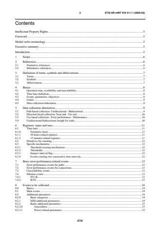
Contents
Intellectual Property Rights . 5
Foreword . 5
Modal verbs terminology . 5
Executive summary . 5
Introduction . 5
1 Scope . 6
2 References . 6
2.1 Normative references . 6
2.2 Informative references . 6
3 Definition of terms, symbols and abbreviations . 7
3.1 Terms . 7
3.2 Symbols . 7
3.3 Abbreviations . 7
4 Basics . 8
4.1 Operation time, availability and unavailability . 8
4.2 Time base definition . 8
4.3 Events, parameters, objectives . 8
4.4 Limits . 9
4.5 Data collection/elaboration . 9
5 Data collection alternatives . 9
5.1 Path based collection: Unidirectional - Bidirectional . 9
5.2 Direction based collection: Near end - Far end . 10
5.3 Use based collection : Error performance - Maintenance . 10
5.4 Unidirectional/bidirectional insight for radio . 10
6 Registers: types and uses . 11
6.1 Time base . 11
6.1.0 Normative basis . 11
6.1.1 24 hours related registers . 11
6.1.2 15 minutes related registers . 11
6.2 Primitives for counting . 12
6.3 Specific mechanisms . 12
6.3.1 Threshold crossing mechanisms . 12
6.3.2 Thresholds. 12
6.3.3 Suspect interval flag. 12
6.3.4 Events crossing two consecutive time intervals . 12
7 Basic error performance related events . 12
7.1 Error performance events for paths . 12
7.2 Error performance events for connections . 13
7.3 Unavailability events . 13
7.4 Ethernet events . 13
7.4.1 ITU-R . 13
7.4.2 IETF . 13
8 Events to be collected . 14
8.0 Basics . 14
8.1 Main events . 14
8.2 Additional parameters . 14
8.2.0 Basic categories . 14
8.2.1 SDH additional parameters . 14
8.2.2 Radio additional parameters . 15
8.2.2.0 Generalities . 15
8.2.2.1 Power related parameters . 15
ETSI
4 ETSI GR mWT 019 V1.1.1 (2020-02)
8.2.2.2 Adaptive modulation related . 15
8.2.2.3 Switch additional parameters . 15
8.3 Necessary Registers for Maintenance . 16
8.4 Necessary Registers for error performance-monitoring . 16
8.5 Performance Evaluation capabilities of equipment . 16
9 Implementation . 17
10 Conclusion . 17
Annex A: Bibliography . 19
History . 20
ETSI
5 ETSI GR mWT 019 V1.1.1 (2020-02)
Intellectual Property Rights
Essential patents
IPRs essential or potentially essential to normative deliverables may have been declared to ETSI. The information
pertaining to these essential IPRs, if any, is publicly available for ETSI members and non-members, and can be found
in ETSI SR 000 314: "Intellectual Property Rights (IPRs); Essential, or potentially Essential, IPRs notified to ETSI in
respect of ETSI standards", which is available from the ETSI Secretariat. Latest updates are available on the ETSI Web
server (https://ipr.etsi.org/).
Pursuant to the ETSI IPR Policy, no investigation, including IPR searches, has been carried out by ETSI. No guarantee
can be given as to the existence of other IPRs not referenced in ETSI SR 000 314 (or the updates on the ETSI Web
server) which are, or may be, or may become, essential to the present document.
Trademarks
The present document may include trademarks and/or tradenames which are asserted and/or registered by their owners.
ETSI claims no ownership of these except for any which are indicated as being the property of ETSI, and conveys no
right to use or reproduce any trademark and/or tradename. Mention of those trademarks in the present document does
not constitute an endorsement by ETSI of products, services or organizations associated with those trademarks.
Foreword
This Group Report (GR) has been produced by ETSI Industry Specification Group (ISG) millimetre Wave
Transmission (mWT).
Modal verbs terminology
In the present document "should", "should not", "may", "need not", "will", "will not", "can" and "cannot" are to be
interpreted as described in clause 3.2 of the ETSI Drafting Rules (Verbal forms for the expression of provisions).
"must" and "must not" are NOT allowed in ETSI deliverables except when used in direct citation.
Executive summary
In order to allow a correct evaluation of the operation of equipment and systems, as well as to allow proper
maintenance, a collection of events by equipment can be used. The present document summarizes the mechanisms of
such collection, valid for Plesiochronous Digital Hierarchy (PDH)/Synchronous Digital Hierarchy (SDH) applications
and proposes specific mechanisms for the Ethernet radio.
Introduction
The present document describes the collection of events necessary to allow the activities related to maintenance and
performance evaluation, traditionally based on contents of registers inside the equipment, in addition or alternatively to
independent network based measurements.
Such description was very detailed for the PDH/SDH applications, widely used before the massive introduction of
packed based technology in networks/equipment.
With this technological evolution, it is necessary to study if there is still need for similar measurements, and if similar
mechanisms can still be considered useful, or if a new approach is consider appropriate.
In case the basic concepts are still valid, there is a need to relate the collection of data available from equipment to the
specific packed based environment.
ETSI
6 ETSI GR mWT 019 V1.1.1 (2020-02)
1 Scope
The present document is aimed to define proper error performance and maintenance oriented parameters for radio, both
in cases of transport of traditional PDH/SDH technologies, and in cases of use of more recent Ethernet based traffic.
2 References
2.1 Normative references
Normative references are not applicable in the present document.
2.2 Informative references
References are either specific (identified by date of publication and/or edition number or version number) or
non-specific. For specific references, only the cited version applies. For non-specific references, the latest version of the
referenced document (including any amendments) applies.
NOTE: While any hyperlinks included in this clause were valid at the time of publication, ETSI cannot guarantee
their long term validity.
The following referenced documents are not necessary for the application of the present document but they assist the
user with regard to a particular subject area.
[i.1] Recommendation ITU-T G.784: "Digital transmission systems - Terminal equipments - Principal
characteristics of multiplexing equipment for the synchronous digital hierarchy".
[i.2] Recommendation ITU-R F.750-4: "architectures and functional aspects of radio-relay systems for
synchronous digital hierarchy (SDH)-based networks".
[i.3] ETSI EN 301 129: "Transmission and Multiplexing (TM); Digital Radio Relay Systems (DRRS);
Synchronous Digital Hierarchy (SDH); System performance monitoring parameters of SDH
DRRS".
[i.4] Recommendation ITU-T G.826: "Error performance parameters and objectives for international,
constant bit rate digital paths at or above the primary rate".
[i.5] Recommendation ITU-T G.827: "Availability parameters and objectives for path elements of
international constant bit rate digital paths at or above the primary rate".
[i.6] Recommendation ITU-T G.828: "Error performance parameters and objectives for international,
constant bit rate synchronous digital paths".
[i.7] Recommendation ITU-R F.2113: "Error performance and availability objectives and requirements
for real point-to-point packet-based radio links".
[i.8] Recommendation ITU-T G.7710/Y.1701: "Common equipment management function
requirements".
[i.9] IETF RFC 8561: "A YANG model for Microwave Radio Links".
[i.10] Recommendation ITU-T G.8013/Y.1731: "Common equipment management function
requirements".
ETSI
7 ETSI GR mWT 019 V1.1.1 (2020-02)
3 Definition of terms, symbols and abbreviations
3.1 Terms
Void.
3.2 Symbols
Void.
3.3 Abbreviations
For the purposes of the present document, the following abbreviations apply:
AIS Alarm Indication Signal
AR Availability Ratio
AU Administrative Unit
BBE Background Block Error
BBER Background Block Error Ratio
BER Bit Error Ratio
BIP-N Bit Interleaved parity of order N
BIS Bringing Into Service
BNM Bandwidth Notification Message
CSES Consecutive SES
EB Errored Block
ES Errored Second
ESR Errored Second Ratio
FC Failure Count
FER Frame Error Ratio
FLR Frame Loss Ratio
FLR Frame Loss Ratio
FSRC Failed Switch Request Count
FSRD Failed Switch Request Duration
IETF Internet Engineering Task Force
LB Lost Block
LOS Loss Of Signal
Mo Mean time between outages
OAM Operation And Maintenence
OFS Out of Frame Seconds
OI Outage Intensity
OOF Out Of Frame
PDH Plesiochronous Digital Hierarchy
PE Path Element
PEA Percent Ethernet service Availability
PEU Percent Ethernet service Unavailability
PJE Pointer Justification Event
PSA Protection Switched Actual
PSAC Protection Switch Actual Count
PSAD Protection Switch Actual Duration
PSR Protection Switched Request
PSRC Protection Switch Request Count
PSRD Protection Switch Request Duration
RBER Residual Bit Error Ratio
RF Radio Frequency
RL Received Level
RLTM Received Level Tide Mark
RLTS Received Level Threshold Seconds
RX Receiver
ETSI
8 ETSI GR mWT 019 V1.1.1 (2020-02)
SDH Synchronous Digital Hierarchy
SEPI Severely Errored Period Intensity
SES Severely Errored Second
SESETH Severely Errored Second Ethernet
SESR Severely Errored Second Ratio
TCN Threshold Crossing Notification
TL Transmitted Level
TLTM Transmitted Level Tide Mark
TLTS Transmitted Level Threshold Seconds
TM Tide Mark
TX Transmitter
UAS UnAvailable Seconds
UR Unavailability Ratio
4 Basics
4.1 Operation time, availability and unavailability
Depending on propagation conditions, traffic transmission in every real link forming part of a transmission network can
be affected by impairments, which can result to different conditions, during operating time.
Traditionally, operating time is subdivided into two main categorizations:
- Periods where transmission is possible, in normal or degraded conditions (available time).
- Periods where transmission is not possible, due to the "long" persistence of very bad conditions (unavailable
time).
4.2 Time base definition
In order to define limits for parameters, a proper definition of suitable observation time is required.
Different time bases have been defined for the different uses:
- Unavailability limits is referred to for one year period.
- Error performance objectives are defined for one month period.
- Impairments are evaluated on one second base.
Other time bases (15 minutes, 24 hours, 1 day, 2 days, 7 days) are also defined to be used for BIS/maintenance scope, in
related ITU-T M series recommendations.
4.3 Events, parameters, objectives
In general, impairments may result in seconds where error conditions are present, which can be associated to specific
classes, depending on type of errors. One second belonging to one specific class constitutes an event.
In an observation period, for any event, a specific parameter can be defined (and calculated) based on some arithmetic
operations; typically, the operation consists in the ratio between the number of events and the total number of seconds.
For each parameter, the maximum acceptable value (or percentage of time) constitutes the objective.
For each real link, the value of error performance and availability objectives to be guaranteed on a long-term bases can
be calculated according to ITU-R specific Recommendations.
Compliance with such objectives for each link is achieved by proper link design.
ETSI
9 ETSI GR mWT 019 V1.1.1 (2020-02)
4.4 Limits
During the equipment operating time, a limit for the overall unavailable time is specified in the observation period.
In the available time, a limit is fixed for each parameter defined in the related recommendation (long term for error
performance scope, short term for maintenance) within proper time intervals.
4.5 Data collection/elaboration
In order to ascertain compliance with objectives, basic info, rated to events (detected with 1s time base), has to be
collected by means of proper registers, according to the duration of the required time base, allowing an evaluation of
parameters.
Due to the fact that some time bases are quite long, it was considered not practical to collect data in equipment with
very high reliability, since specific mechanisms (such as non-volatile memory, safe backup) would be required,
impacting on the complexity and cost of the systems (especially in early times).
In addition, equipment cannot be aware of specific maintenance actions decided by the network, potentially impacting
measurements.
The equipment was asked to collect the information by means of an embedded set of specific registers, addressing
limited periods of time, which can be accessed by network Operating Systems (OS).
OSs collect information, allowing long term evaluation, so registers can be reused by the equipment and eventual
equipment loss of data can have limited impact.
5 Data collection alternatives
5.1 Path based collection: Unidirectional - Bidirectional
Data collection can be addressed to several needs, resulting in different procedures and algorithms, and in different sets
of registers.
In a generic network element, data can be collected by looking at the link typology and can be classified as:
• Unidirectional approach, where each single direction is collected separately.
• Bidirectional approach, where the collection is based on an analysis of the Path, information of the two
directions is necessary at each terminal.
The unidirectional approach is simpler to be implemented, since the two directions of link can be assumed as
uncorrelated.
B need to be taken into account when only such direction is available,
In particular, events happening on a direction A
not looking at the other direction state in corresponding time intervals.
The unidirectional evaluation is generally based on direct use of error detection mechanisms, (such as parity bit, BIP-N
etc.) or defect indicators.
The unidirectional collection relates to direction link (or section).
On the contrary, the bidirectional approach requires a joint analysis of behaviours of two directions, since counting for
each direction (e.g. AB) is stopped when the other direction (B A) is in the unavailable state, for the definition of
path.
If only one direction is unavailable, counting of events is stopped for both directions, and unavailability counters only is
incremented for bo
...
Questions, Comments and Discussion
Ask us and Technical Secretary will try to provide an answer. You can facilitate discussion about the standard in here.
Loading comments...