


ASTM D5405/D5405M-98(2015)
(Test Method)Standard Test Method for Conducting Time-to-Failure (Creep-Rupture) Tests of Joints Fabricated from Nonbituminous Organic Roof Membrane Material
Standard Test Method for Conducting Time-to-Failure (Creep-Rupture) Tests of Joints Fabricated from Nonbituminous Organic Roof Membrane Material
SIGNIFICANCE AND USE
5.1 An important factor affecting the performance of joints of nonbituminous membranes is their ability to remain bonded over the membrane's expected service life. Time-to-failure tests provide a means of characterizing the behavior of joints under constant load over time.
5.2 Creep is a sensitive index of rheological properties that depend on material, load, temperature, and time. Time-to-failure data that are obtained over a relatively short time period can evaluate one factor affecting a joint's ability to withstand static loading over a relatively long time period.
5.3 Time-to-failure data for joints of nonbituminous organic roof membrane specimens can be used for the following: (1) to provide a measure of the load-carrying ability of the joint as a function of time at various levels of load, temperature, and relative humidity; (2) to characterize the joint with regard to factors affecting performance, such as surface preparation of the adherend, solvent-based adhesive thickness and open time, environment during adhesive application and cure, and temperature of thermal welding processes; and (3) to compare the effects of different bonding processes or adhesive bonding materials on joint performance.
5.4 While it is considered that the results obtained by this laboratory test may afford a measure of the performance of seams in service, provided that load, temperature, and humidity conditions are known, no direct correlation has been established.
SCOPE
1.1 This test method covers laboratory determination of the time-to-failure (creep-rupture) of joints fabricated from nonbituminous organic roof membrane material. The test method covers both T-peel and lap-shear joints subjected to constant tensile load under controlled environmental conditions. The joints, made from either unreinforced or fabric-reinforced membrane material, are prepared in the laboratory or sampled from roofs in service.
1.2 Sheet materials from which the joints are fabricated include vulcanized rubbers, nonvulcanized polymeric sheets, and thermoplastics. The bonding methods for joint formation include the use of liquid-based adhesives, preformed tapes, and thermal and solvent weld processes.
1.3 The values stated in either SI units or inch-pound units are to be regarded separately as standard. The values stated in each system may not be exact equivalents; therefore, each system shall be used independently of the other. Combining values from the two systems may result in non-conformance with the standard.
1.4 This standard does not purport to address all of the safety concerns, if any, associated with its use. It is the responsibility of the user of this standard to establish appropriate safety and health practices and determine the applicability of regulatory limitations prior to use.
General Information
Buy Standard
Standards Content (Sample)
NOTICE: This standard has either been superseded and replaced by a new version or withdrawn.
Contact ASTM International (www.astm.org) for the latest information
Designation: D5405/D5405M − 98 (Reapproved 2015)
Standard Test Method for
Conducting Time-to-Failure (Creep-Rupture) Tests of Joints
Fabricated from Nonbituminous Organic Roof Membrane
Material
This standard is issued under the fixed designation D5405/D5405M; the number immediately following the designation indicates the
year of original adoption or, in the case of revision, the year of last revision. A number in parentheses indicates the year of last
reapproval. A superscript epsilon (´) indicates an editorial change since the last revision or reapproval.
1. Scope D1079 Terminology Relating to Roofing and Waterproofing
D1876 Test Method for Peel Resistance of Adhesives (T-
1.1 This test method covers laboratory determination of the
Peel Test)
time-to-failure (creep-rupture) of joints fabricated from nonbi-
tuminous organic roof membrane material. The test method
3. Terminology
covers both T-peel and lap-shear joints subjected to constant
3.1 Definitions—For definitions of terms used in this test
tensile load under controlled environmental conditions. The
method, refer to Terminology D907 and D1079.
joints, made from either unreinforced or fabric-reinforced
3.2 Definitions of Terms Specific to This Standard:
membrane material, are prepared in the laboratory or sampled
3.2.1 creep-rupture test—a test that measures the time-to-
from roofs in service.
failure of a specimen subjected to a constant load; progressive
1.2 Sheet materials from which the joints are fabricated
specimen deformation may also be measured.
include vulcanized rubbers, nonvulcanized polymeric sheets,
3.2.2 failure—rupture of the bond resulting in complete
and thermoplastics. The bonding methods for joint formation
separation of its adherends under the test conditions; or,
includetheuseofliquid-basedadhesives,preformedtapes,and
alternatively, rupture of the membrane material away from the
thermal and solvent weld processes.
bonded section of the test specimen (that is, material rupture).
1.3 The values stated in either SI units or inch-pound units
3.2.3 time-to-failure—the period of time beginning when a
are to be regarded separately as standard. The values stated in
joint specimen is placed under load and ending when failure
each system may not be exact equivalents; therefore, each
occurs.
system shall be used independently of the other. Combining
values from the two systems may result in non-conformance
4. Summary of Test Method
with the standard.
4.1 This test method is a creep-rupture test without mea-
1.4 This standard does not purport to address all of the
surement of specimen deformation. The time-to-failure, in
safety concerns, if any, associated with its use. It is the
hours, of joints fabricated from nonbituminous organic roof
responsibility of the user of this standard to establish appro-
membrane materials is measured when subject to constant
priate safety and health practices and determine the applica-
deadweight loads under controlled temperature and humidity
bility of regulatory limitations prior to use.
conditions.
2. Referenced Documents
5. Significance and Use
2.1 ASTM Standards:
5.1 An important factor affecting the performance of joints
D816 Test Methods for Rubber Cements
of nonbituminous membranes is their ability to remain bonded
D907 Terminology of Adhesives
over the membrane’s expected service life. Time-to-failure
tests provide a means of characterizing the behavior of joints
under constant load over time.
This test method is under the jurisdiction ofASTM Committee D08 on Roofing
5.2 Creep is a sensitive index of rheological properties that
and Waterproofing and is the direct responsibility of Subcommittee D08.18 on
Nonbituminous Organic Roof Coverings.
depend on material, load, temperature, and time. Time-to-
Current edition approved Nov. 1, 2015. Published November 2015. Originally
failure data that are obtained over a relatively short time period
approved in 1993. Last previous edition approved in 2011 as D5405/D5405M – 98
ɛ1
can evaluate one factor affecting a joint’s ability to withstand
(2011) . DOI: 10.1520/D5405_D5405M-98R15.
For referenced ASTM standards, visit the ASTM website, www.astm.org, or static loading over a relatively long time period.
contact ASTM Customer Service at service@astm.org. For Annual Book of ASTM
5.3 Time-to-failure data for joints of nonbituminous organic
Standards volume information, refer to the standard’s Document Summary page on
the ASTM website. roof membrane specimens can be used for the following: (1)to
Copyright © ASTM International, 100 Barr Harbor Drive, PO Box C700, West Conshohocken, PA 19428-2959. United States
D5405/D5405M − 98 (2015)
provide a measure of the load-carrying ability of the joint as a
function of time at various levels of load, temperature, and
relative humidity; (2) to characterize the joint with regard to
factors affecting performance, such as surface preparation of
the adherend, solvent-based adhesive thickness and open time,
environment during adhesive application and cure, and tem-
perature of thermal welding processes; and (3) to compare the
effects of different bonding processes or adhesive bonding
materials on joint performance.
5.4 While it is considered that the results obtained by this
laboratory test may afford a measure of the performance of
seamsinservice,providedthatload,temperature,andhumidity
conditions are known, no direct correlation has been estab-
lished.
6. Apparatus
6.1 Test Chamber,ofsufficientsizetoholdaminimumof15
specimens. The height of the chamber shall be sufficient to
allow suspension of the deadweight loads and specimen
deformation during testing. The chamber shall be structurally
capable of supporting the loads anticipated during testing
without appreciable deflection.
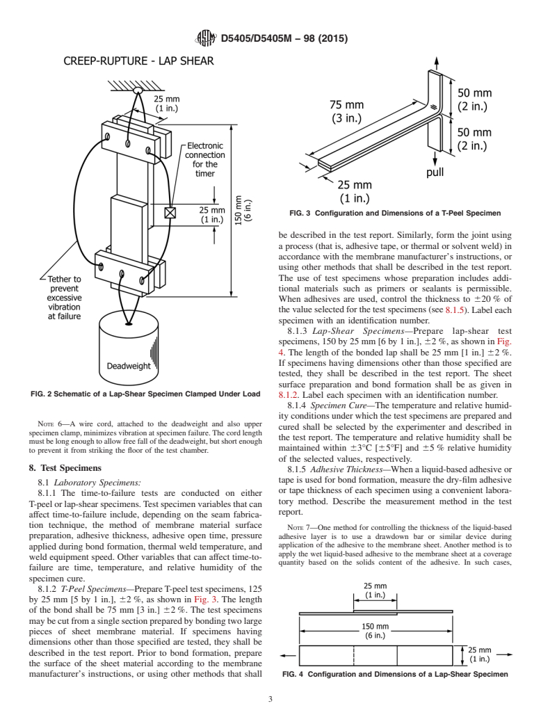
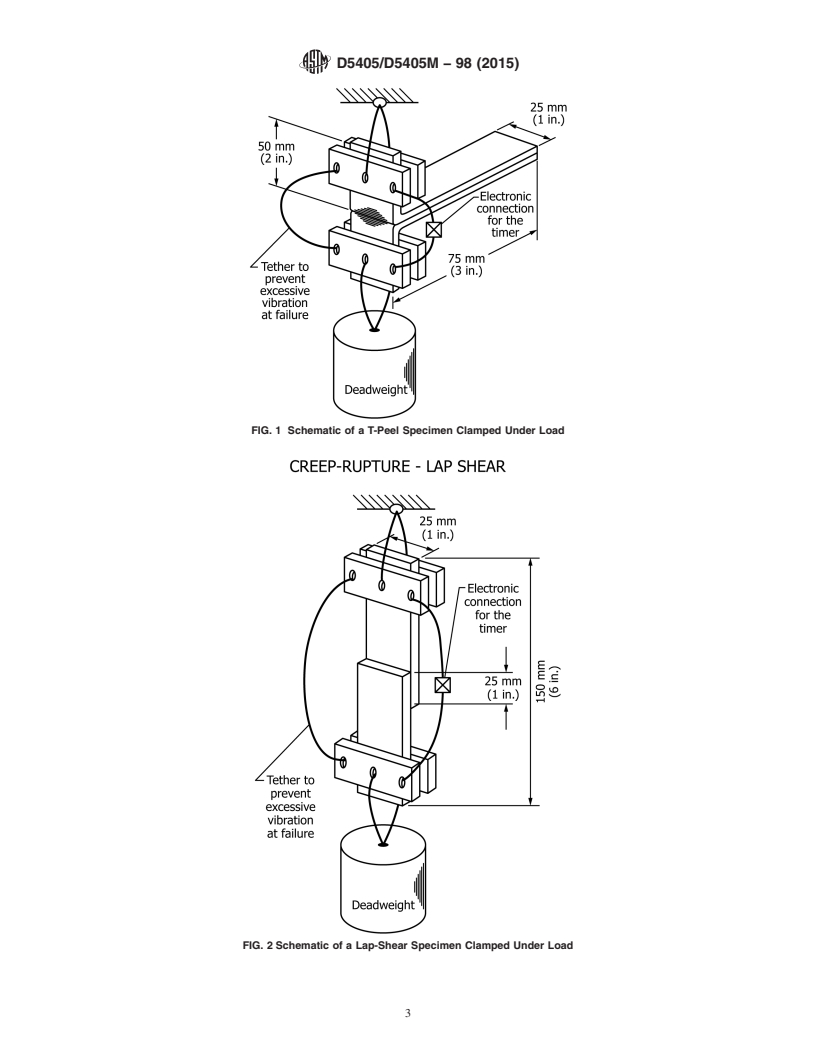
FIG. 1 Schematic of a T-Peel Specimen Clamped Under Load
NOTE 1—A minimum height of 600 mm [24 in.] is suitable for the
specimen sizes described in this test method if they are not extremely
extensible. A taller chamber may be needed if they are extremely
An example of such a device is a large tray, suspended on
extensible.
pulleys, which supports the loads attached to the bottom of the
6.1.1 Temperature and Humidity Control—The control of
specimens. Lowering the tray allows all test specimens and
temperature and humidity is important, since small changes in
deadweights attached to them to be suspended freely at once.
these variables may produce large changes in time-to-failure.
The temperature and relative humidity within the chamber
NOTE 4—If each specimen has its own timer device (see 6.5), it is not
shall be controlled within 63°C [6 5°F] and 65 % relative necessary to load all specimens simultaneously.
humidity, respectively, over the duration of the test. Any
6.5 Timer Device, for recording the total time over which
deviations from these limits shall be given in the test report.
eachindividualspecimenisunderload,orformarkingthetime
The selected temperature and humidity conditions shall be
at which failure of each specimen occurs.The sensitivity of the
uniform throughout the enclosed space (63°C or 65°F and
timer shall be as follows:
65 %relativehumidity).Ifthisuniformityisachievedthrough
Failure Time Timer Sensitivity
mechanical air circulation, it shall not cause the specimens to
#25 h 0.1 min
>25 and#100 h 0.01 h
sway, vibrate, or be otherwise disturbed.
>100 h 0.1 h
NOTE 2—Suggested test conditions are as follows: (1) normal ambient
NOTE 5—For investigations involving multiple specimens in the
temperature (approximately 23°C or 73°F) and humidity (50 % relative
chamber, a computer-controlled timer that records the time-to-failure has
humidity); and (2) extremes to which the seams may be subjected in
been found to be satisfactory. In this case, a micro-electrical circuit
service.
connectedtothecomputerissetupforeachspecimen.Thecircuitconsists
6.2 Specimen and Load Clamping—The chamber shall be
of a wire loop, of which one segment is a short length of wire (trigger
wire) attached to each grip on the test specimen and set to stop the
equipped with a means for clamping the joint specimens
computer clock when failure occurs.At the point of attachment at the top
vertically to the top of the interior of the chamber, or other
grip, the trigger wire is inserted in an electrical connector. When the
suitable upper support. Also, a clamp shall be provided to
specimen fails and the deadweight on the lower grip falls, the trigger wire
secure the deadweight loads to the bottom of the joint
is pulled from the connector, breaking the circuit and stopping the clock.
specimens. Figs. 1 and 2 show a suggested clamping arrange-
ment including the deadweight load. 7. Vibration Control
7.1 Because the time-to-failure tests are sensitive to
6.3 Deadweight Loads, of appropriate mass (see Section
10). vibration, select a location of the testing apparatus for mini-
mum disturbance. When a vibration-free location is not
NOTE 3—It is convenient to have available a means of providing
available, the testing apparatus shall be designed so that the
variableloadsthatmaydifferfromtesttotest,dependingontheproperties
specimens are isolated from vibration. In addition, precautions
of the joint specimens and test conditions. Hollow pipe nipples containing
lead shot and sealed with end caps provide convenient deadweights. The
shall be taken to avoid vibration caused by the falling dead-
mass of the deadweights is adjusted by adding or removing lead shot.
weights at specimen failure. Caution shall be exercised during
6.4 Load Application Mechanism—This device allows for testing to avoid vibration due to normal laboratory activities
placing all of the joint specimens under load simultaneously. such as opening and closing doors and bench drawers.
D5405/D5405M − 98 (2015)
FIG. 3 Configuration and Dimensions of a T-Peel Specimen
be described in the test report. Similarly, form the joint using
a process (that is, adhesive tape, or thermal or solvent weld) in
accordance with the membrane manufacturer’s instructions, or
using other methods that shall be described in the test report.
The use of test specimens whose preparation includes addi-
tional materials such as primers or sealants is permissible.
When adhesives are used, control the thickness to 620 % of
thevalueselectedforthetestspecimens(see8.1.5).Labeleach
specimen with an identification number.
8.1.3 Lap-Shear Specimens—Prepare lap-shear test
specimens, 150 by 25 mm [6 by 1 in.], 62 %, as shown in Fig.
4. The length of the bonded lap shall be 25 mm [1 in.] 62%.
If specimens having dimensions other than those specified are
tested, they shall be described in the test report. The sheet
surface preparation and bond formation shall be as given in
FIG. 2 Schematic of a Lap-Shear Specimen Clamped Under Load
8.1.2. Label each specimen with an identification number.
8.1.4 Specimen Cure—The temperature and relative humid-
ity conditions under which the test specimens are prepared and
NOTE 6—A wire cord, attached to the deadweight and also upper
cured shall be selected by the experimenter and described in
specimen clamp, minimizes vibration at specimen failure.The cord length
the test report. The temperature and relative humidity shall be
mustbelongenoughtoallowfreefallofthedeadweight,butshortenough
maintained within 63°C [65°F] and 65 % relative humidity
to prevent it from striking the floor of the test chamber.
of the selected values, respectively.
8. Test Specimens
8.1.5 Adhesive Thickness—When a liquid-based adhesive or
tape is used for bond formation, measure the dry-film adhesive
8.1 Laboratory Specimens:
or tape thickness of each specimen using a convenient labora-
8.1.1 The time-to-failure tests are conducted on either
tory method. Describe the measurement method in the test
T-peelorlap-shearspecimens.Testspecimenvariablesthatcan
report.
affect time-to-failure include, depending on the seam fabrica-
tion technique, the method of membrane material surface
NOTE 7—One method for controlling the thickness of the liquid-based
preparation, adhesive thickness, adhesive open time, pressure adhesive layer is to use a drawdown bar or similar device during
application of the adhesive to the membrane sheet. Another method is to
applied during bond formation, thermal weld temperature, and
apply the wet liquid-based adhesive to the membrane sheet at a coverage
weld equipment speed. Other variables that can affect time-to-
quantity based on the solids content of the adhesive. In such cases,
failure are time, temperature, and relative humidity of the
specimen cure.
8.1.2 T-Peel Specimens—PrepareT-peel test specimens, 125
by 25 mm [5 by 1 in.], 62 %, as shown in Fig. 3. The length
of the bond shall be 75 mm [3 in.] 62 %. The test specimens
maybecutfromasinglesectionpreparedbybondingtwolarge
pieces of sheet membrane material. If specimens having
dimensions other than those specified are tested, they shall be
described in the test report. Prior to bond formation, prepare
the surface of the sheet material according to the membrane
manufacturer’s instructions, or using other methods that shall FIG. 4 Configuration and Dimensions of a Lap-Shear Specimen
D5405/D5405M − 98 (2015)
measurements should be performed to establish the thickness-coverage experienced by the seam in service. Pretesting specimens under selected
relation; if necessary, consult with the membrane manufacturer for loads is useful to estimate the time-to-failure of the specimens for the
assistance in determining coverage quantities that will provide specific loading conditions used in this test method.
adhesive thicknesses. NOTE 11—Conducting successive tests at loads that are multiples of
each other provides a means for determining the effect of load on the
8.2 Field Specimens:
creep-rupture life of the joint specimen.
8.2.1 T-peel or lap-shear specimens, having the dimensions
given in Figs. 1 and 2, respectively, may be prepared from
11. Procedure
seams sampled from roofs in service. If the specimens have
11.1 Place the specimens in the upper clamps of the
dimensions other than those given in Figs. 1 and 2, the
chamber by gripping 25 mm [1 in.], 610 %, of the free
specimen dimensions shall be given in the test report. In the
(unadhered) specimen end. Take care to avoid eccentric load-
case of lap-shear specimens, when the length of the bond is
ing of the specimen.
greater than that given in Fig. 2, precautions must be taken to
select sufficiently high deadloads so that failure will occur in a
11.2 Attach the lower clamps and selected loads to the
reasonable testing time. specimens; grip 25 mm. [1.0 in], 610 %, of the free end of the
8.2.2 Record all available pertinent info
...
This document is not an ASTM standard and is intended only to provide the user of an ASTM standard an indication of what changes have been made to the previous version. Because
it may not be technically possible to adequately depict all changes accurately, ASTM recommends that users consult prior editions as appropriate. In all cases only the current version
of the standard as published by ASTM is to be considered the official document.
´1
Designation: D5405/D5405M − 98 (Reapproved 2011) D5405/D5405M − 98 (Reapproved
2015)
Standard Test Method for
Conducting Time-to-Failure (Creep-Rupture) Tests of Joints
Fabricated from Nonbituminous Organic Roof Membrane
Material
This standard is issued under the fixed designation D5405/D5405M; the number immediately following the designation indicates the
year of original adoption or, in the case of revision, the year of last revision. A number in parentheses indicates the year of last
reapproval. A superscript epsilon (´) indicates an editorial change since the last revision or reapproval.
ε NOTE—Units information was editorially revised in June 2011.
1. Scope
1.1 This test method covers laboratory determination of the time-to-failure (creep-rupture) of joints fabricated from
nonbituminous organic roof membrane material. The test method covers both T-peel and lap-shear joints subjected to constant
tensile load under controlled environmental conditions. The joints, made from either unreinforced or fabric-reinforced membrane
material, are prepared in the laboratory or sampled from roofs in service.
1.2 Sheet materials from which the joints are fabricated include vulcanized rubbers, nonvulcanized polymeric sheets, and
thermoplastics. The bonding methods for joint formation include the use of liquid-based adhesives, preformed tapes, and thermal
and solvent weld processes.
1.3 The values stated in either SI units or inch-pound units are to be regarded separately as standard. The values stated in each
system may not be exact equivalents; therefore, each system shall be used independently of the other. Combining values from the
two systems may result in non-conformance with the standard.
1.4 This standard does not purport to address all of the safety concerns, if any, associated with its use. It is the responsibility
of the user of this standard to establish appropriate safety and health practices and determine the applicability of regulatory
limitations prior to use.
2. Referenced Documents
2.1 ASTM Standards:
D816 Test Methods for Rubber Cements
D907 Terminology of Adhesives
D1079 Terminology Relating to Roofing and Waterproofing
D1876 Test Method for Peel Resistance of Adhesives (T-Peel Test)
3. Terminology
3.1 Definitions—For definitions of terms used in this test method, refer to Terminology D907 and D1079.
3.2 Definitions of Terms Specific to This Standard:
3.2.1 creep-rupture test—a test that measures the time-to-failure of a specimen subjected to a constant load; progressive
specimen deformation may also be measured.
3.2.2 failure—rupture of the bond resulting in complete separation of its adherends under the test conditions; or, alternatively,
rupture of the membrane material away from the bonded section of the test specimen (that is, material rupture).
3.2.3 time-to-failure—the period of time beginning when a joint specimen is placed under load and ending when failure occurs.
This test method is under the jurisdiction of ASTM Committee D08 on Roofing and Waterproofing and is the direct responsibility of Subcommittee D08.18 on
Nonbituminous Organic Roof Coverings.
Current edition approved May 1, 2011Nov. 1, 2015. Published June 2011November 2015. Originally approved in 1993. Last previous edition approved in 20042011 as
ɛ1
D5405 – 98D5405/D5405M – 98 (2011) (2004). . DOI: 10.1520/D5405_D5405M-98R11E01.10.1520/D5405_D5405M-98R15.
For referenced ASTM standards, visit the ASTM website, www.astm.org, or contact ASTM Customer Service at service@astm.org. For Annual Book of ASTM Standards
volume information, refer to the standard’s Document Summary page on the ASTM website.
Copyright © ASTM International, 100 Barr Harbor Drive, PO Box C700, West Conshohocken, PA 19428-2959. United States
D5405/D5405M − 98 (2015)
4. Summary of Test Method
4.1 This test method is a creep-rupture test without measurement of specimen deformation. The time-to-failure, in hours, of
joints fabricated from nonbituminous organic roof membrane materials is measured when subject to constant deadweight loads
under controlled temperature and humidity conditions.
5. Significance and Use
5.1 An important factor affecting the performance of joints of nonbituminous membranes is their ability to remain bonded over
the membrane’s expected service life. Time-to-failure tests provide a means of characterizing the behavior of joints under constant
load over time.
5.2 Creep is a sensitive index of rheological properties that depend on material, load, temperature, and time. Time-to-failure data
that are obtained over a relatively short time period can evaluate one factor affecting a joint’s ability to withstand static loading
over a relatively long time period.
5.3 Time-to-failure data for joints of nonbituminous organic roof membrane specimens can be used for the following: (1) to
provide a measure of the load-carrying ability of the joint as a function of time at various levels of load, temperature, and relative
humidity; (2) to characterize the joint with regard to factors affecting performance, such as surface preparation of the adherend,
solvent-based adhesive thickness and open time, environment during adhesive application and cure, and temperature of thermal
welding processes; and (3) to compare the effects of different bonding processes or adhesive bonding materials on joint
performance.
5.4 While it is considered that the results obtained by this laboratory test may afford a measure of the performance of seams
in service, provided that load, temperature, and humidity conditions are known, no direct correlation has been established.
6. Apparatus
6.1 Test Chamber, of sufficient size to hold a minimum of 15 specimens. The height of the chamber shall be sufficient to allow
suspension of the deadweight loads and specimen deformation during testing. The chamber shall be structurally capable of
supporting the loads anticipated during testing without appreciable deflection.
NOTE 1—A minimum height of 600 mm [24 in.] is suitable for the specimen sizes described in this test method if they are not extremely extensible.
A taller chamber may be needed if they are extremely extensible.
6.1.1 Temperature and Humidity Control—The control of temperature and humidity is important, since small changes in these
variables may produce large changes in time-to-failure. The temperature and relative humidity within the chamber shall be
controlled within 63°C [6 5°F] and 65 % relative humidity, respectively, over the duration of the test. Any deviations from these
limits shall be given in the test report. The selected temperature and humidity conditions shall be uniform throughout the enclosed
space (63°C or 65°F and 65 % relative humidity). If this uniformity is achieved through mechanical air circulation, it shall not
cause the specimens to sway, vibrate, or be otherwise disturbed.
NOTE 2—Suggested test conditions are as follows: (1) normal ambient temperature (approximately 23°C or 73°F) and humidity (50 % relative
humidity); and (2) extremes to which the seams may be subjected in service.
6.2 Specimen and Load Clamping —Clamping—The chamber shall be equipped with a means for clamping the joint specimens
vertically to the top of the interior of the chamber, or other suitable upper support. Also, a clamp shall be provided to secure the
deadweight loads to the bottom of the joint specimens. Figs. 1 and 2 show a suggested clamping arrangement including the
deadweight load.
6.3 Deadweight Loads, of appropriate mass (see Section 10).
NOTE 3—It is convenient to have available a means of providing variable loads that may differ from test to test, depending on the properties of the
joint specimens and test conditions. Hollow pipe nipples containing lead shot and sealed with end caps provide convenient deadweights. The mass of the
deadweights is adjusted by adding or removing lead shot.
6.4 Load Application Mechanism —Mechanism—This device allows for placing all of the joint specimens under load
simultaneously. An example of such a device is a large tray, suspended on pulleys, which supports the loads attached to the bottom
of the specimens. Lowering the tray allows all test specimens and deadweights attached to them to be suspended freely at once.
NOTE 4—If each specimen has its own timer device (see 6.5), it is not necessary to load all specimens simultaneously.
6.5 Timer Device, for recording the total time over which each individual specimen is under load, or for marking the time at
which failure of each specimen occurs. The sensitivity of the timer shall be as follows:
Failure Time Timer Sensitivity
#25 h 0.1 min
>25 and #100 h 0.01 h
>100 h 0.1 h
D5405/D5405M − 98 (2015)
FIG. 1 Schematic of a T-Peel Specimen Clamped Under Load
FIG. 2 Schematic of a Lap-Shear Specimen Clamped Under Load
D5405/D5405M − 98 (2015)
Failure Time Timer Sensitivity
#25 h 0.1 min
>25 and #100 h 0.01 h
>100 h 0.1 h
NOTE 5—For investigations involving multiple specimens in the chamber, a computer-controlled timer that records the time-to-failure has been found
to be satisfactory. In this case, a micro-electrical circuit connected to the computer is set up for each specimen. The circuit consists of a wire loop, of
which one segment is a short length of wire (trigger wire) attached to each grip on the test specimen and set to stop the computer clock when failure
occurs. At the point of attachment at the top grip, the trigger wire is inserted in an electrical connector. When the specimen fails and the deadweight on
the lower grip falls, the trigger wire is pulled from the connector, breaking the circuit and stopping the clock.
7. Vibration Control
7.1 Because the time-to-failure tests are sensitive to vibration, select a location of the testing apparatus for minimum
disturbance. When a vibration-free location is not available, the testing apparatus shall be designed so that the specimens are
isolated from vibration. In addition, precautions shall be taken to avoid vibration caused by the falling deadweights at specimen
failure. Caution shall be exercised during testing to avoid vibration due to normal laboratory activities such as opening and closing
doors and bench drawers.
NOTE 6—A wire cord, attached to the deadweight and also upper specimen clamp, minimizes vibration at specimen failure. The cord length must be
long enough to allow free fall of the deadweight, but short enough to prevent it from striking the floor of the test chamber.
8. Test Specimens
8.1 Laboratory Specimens:
8.1.1 The time-to-failure tests are conducted on either T-peel or lap-shear specimens. Test specimen variables that can affect
time-to-failure include, depending on the seam fabrication technique, the method of membrane material surface preparation,
adhesive thickness, adhesive open time, pressure applied during bond formation, thermal weld temperature, and weld equipment
speed. Other variables that can affect time-to-failure are time, temperature, and relative humidity of the specimen cure.
8.1.2 T-Peel Specimens—Prepare T-peel test specimens, 125 by 25 mm [5 by 1 in.], 62 %, as shown in Fig. 3. The length of
the bond shall be 75 mm [3 in.] 62 %. The test specimens may be cut from a single section prepared by bonding two large pieces
of sheet membrane material. If specimens having dimensions other than those specified are tested, they shall be described in the
test report. Prior to bond formation, prepare the surface of the sheet material according to the membrane manufacturer’s
instructions, or using other methods that shall be described in the test report. Similarly, form the joint using a process (that is,
adhesive tape, or thermal or solvent weld) in accordance with the membrane manufacturer’s instructions, or using other methods
that shall be described in the test report. The use of test specimens whose preparation includes additional materials such as primers
or sealants is permissible. When adhesives are used, control the thickness to 620 % of the value selected for the test specimens
(see 8.1.5). Label each specimen with an identification number.
8.1.3 Lap-Shear Specimens—Prepare lap-shear test specimens, 150 by 25 mm.mm [6 by 1 in.], 62 %, as shown in Fig. 4. The
length of the bonded lap shall be 25 mm [1 in.] 62 %. If specimens having dimensions other than those specified are tested, they
shall be described in the test report. The sheet surface preparation and bond formation shall be as given in 8.1.2. Label each
specimen with an identification number.
8.1.4 Specimen Cure—The temperature and relative humidity conditions under which the test specimens are prepared and cured
shall be selected by the experimenter and described in the test report. The temperature and relative humidity shall be maintained
within 63°C [65°F] and 65 % relative humidity of the selected values, respectively.
8.1.5 Adhesive Thickness—When a liquid-based adhesive or tape is used for bond formation, measure the dry-film adhesive or
tape thickness of each specimen using a convenient laboratory method. Describe the measurement method in the test report.
FIG. 3 Configuration and Dimensions of a T-Peel Specimen
D5405/D5405M − 98 (2015)
FIG. 4 Configuration and Dimensions of a Lap-Shear Specimen
NOTE 7—One method for controlling the thickness of the liquid-based adhesive layer is to use a drawdown bar or similar device during application
of the adhesive to the membrane sheet. Another method is to apply the wet liquid-based adhesive to the membrane sheet at a coverage quantity based
on the solids content of the adhesive. In such cases, measurements should be performed to establish the thickness-coverage relation; if necessary, consult
with the membrane manufacturer for assistance in determining coverage quantities that will provide specific adhesive thicknesses.
8.2 Field Specimens:
8.2.1 T-peel or lap-shear specimens, having the dimensions given in Figs. 1 and 2, respectively, may be prepared from seams
sampled from roofs in service. If the specimens have dimensions other than those given in Figs. 1 and 2, the specimen dimensions
shall be given in the test report. In the case of lap-shear specimens, when the length of the bond is greater than that given in Fig.
2, precautions must be taken to select sufficiently high deadloads so that failure will occur in a reasonable testing time.
...
Questions, Comments and Discussion
Ask us and Technical Secretary will try to provide an answer. You can facilitate discussion about the standard in here.