


ASTM E434-10(2015)
(Test Method)Standard Test Method for Calorimetric Determination of Hemispherical Emittance and the Ratio of Solar Absorptance to Hemispherical Emittance Using Solar Simulation
Standard Test Method for Calorimetric Determination of Hemispherical Emittance and the Ratio of Solar Absorptance to Hemispherical Emittance Using Solar Simulation
ABSTRACT
This test method covers measurement techniques for calorimetrically determining the ratio of solar absorptance to hemispherical emittance using a steady-state method, and for calorimetrically determining the total hemispherical emittance using a transient technique. The main elements of the apparatus include a vacuum system, a cold shroud within the vacuum chamber, instrumentation for temperature measurement, and a solar simulator. Any type of coating may be tested by this test method provided its structure remains stable in vacuum over the temperature range of interest. The substrate shall be machined from flat stock and to a size proportioned to the working area of the chamber.
SCOPE
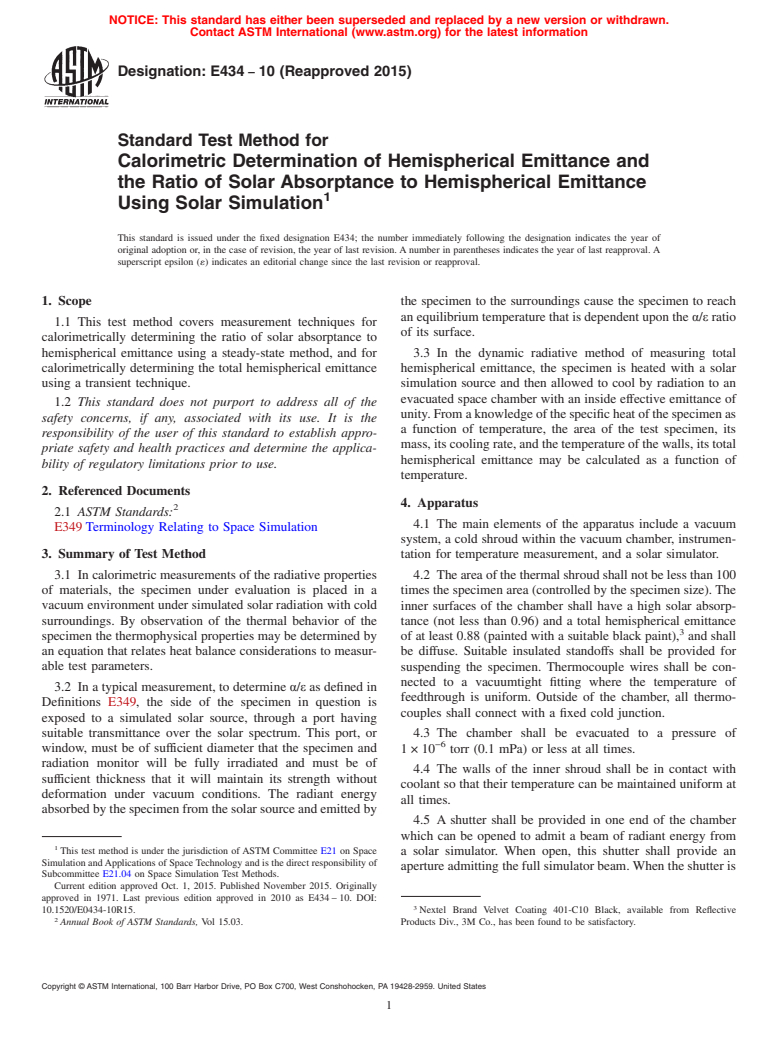
1.1 This test method covers measurement techniques for calorimetrically determining the ratio of solar absorptance to hemispherical emittance using a steady-state method, and for calorimetrically determining the total hemispherical emittance using a transient technique.
1.2 This standard does not purport to address all of the safety concerns, if any, associated with its use. It is the responsibility of the user of this standard to establish appropriate safety and health practices and determine the applicability of regulatory limitations prior to use.
General Information
Buy Standard
Standards Content (Sample)
NOTICE: This standard has either been superseded and replaced by a new version or withdrawn.
Contact ASTM International (www.astm.org) for the latest information
Designation: E434 − 10 (Reapproved 2015)
Standard Test Method for
Calorimetric Determination of Hemispherical Emittance and
the Ratio of Solar Absorptance to Hemispherical Emittance
Using Solar Simulation
This standard is issued under the fixed designation E434; the number immediately following the designation indicates the year of
original adoption or, in the case of revision, the year of last revision.Anumber in parentheses indicates the year of last reapproval.A
superscript epsilon (´) indicates an editorial change since the last revision or reapproval.
1. Scope the specimen to the surroundings cause the specimen to reach
anequilibriumtemperaturethatisdependentupontheα/εratio
1.1 This test method covers measurement techniques for
of its surface.
calorimetrically determining the ratio of solar absorptance to
hemispherical emittance using a steady-state method, and for 3.3 In the dynamic radiative method of measuring total
calorimetrically determining the total hemispherical emittance hemispherical emittance, the specimen is heated with a solar
using a transient technique. simulation source and then allowed to cool by radiation to an
evacuated space chamber with an inside effective emittance of
1.2 This standard does not purport to address all of the
unity.Fromaknowledgeofthespecificheatofthespecimenas
safety concerns, if any, associated with its use. It is the
a function of temperature, the area of the test specimen, its
responsibility of the user of this standard to establish appro-
mass,itscoolingrate,andthetemperatureofthewalls,itstotal
priate safety and health practices and determine the applica-
hemispherical emittance may be calculated as a function of
bility of regulatory limitations prior to use.
temperature.
2. Referenced Documents
4. Apparatus
2.1 ASTM Standards:
4.1 The main elements of the apparatus include a vacuum
E349Terminology Relating to Space Simulation
system, a cold shroud within the vacuum chamber, instrumen-
3. Summary of Test Method tation for temperature measurement, and a solar simulator.
3.1 In calorimetric measurements of the radiative properties 4.2 Theareaofthethermalshroudshallnotbelessthan100
of materials, the specimen under evaluation is placed in a
timesthespecimenarea(controlledbythespecimensize).The
vacuum environment under simulated solar radiation with cold inner surfaces of the chamber shall have a high solar absorp-
surroundings. By observation of the thermal behavior of the
tance (not less than 0.96) and a total hemispherical emittance
specimen the thermophysical properties may be determined by of at least 0.88 (painted with a suitable black paint), and shall
an equation that relates heat balance considerations to measur-
be diffuse. Suitable insulated standoffs shall be provided for
able test parameters. suspending the specimen. Thermocouple wires shall be con-
nected to a vacuumtight fitting where the temperature of
3.2 In a typical measurement, to determine α/ε as defined in
feedthrough is uniform. Outside of the chamber, all thermo-
Definitions E349, the side of the specimen in question is
couples shall connect with a fixed cold junction.
exposed to a simulated solar source, through a port having
suitable transmittance over the solar spectrum. This port, or 4.3 The chamber shall be evacuated to a pressure of
−6
window, must be of sufficient diameter that the specimen and
1×10 torr (0.1 mPa) or less at all times.
radiation monitor will be fully irradiated and must be of
4.4 The walls of the inner shroud shall be in contact with
sufficient thickness that it will maintain its strength without
coolant so that their temperature can be maintained uniform at
deformation under vacuum conditions. The radiant energy
all times.
absorbedbythespecimenfromthesolarsourceandemittedby
4.5 A shutter shall be provided in one end of the chamber
which can be opened to admit a beam of radiant energy from
This test method is under the jurisdiction of ASTM Committee E21 on Space
a solar simulator. When open, this shutter shall provide an
Simulation andApplications of SpaceTechnology and is the direct responsibility of
apertureadmittingthefullsimulatorbeam.Whentheshutteris
Subcommittee E21.04 on Space Simulation Test Methods.
Current edition approved Oct. 1, 2015. Published November 2015. Originally
approved in 1971. Last previous edition approved in 2010 as E434–10. DOI:
10.1520/E0434-10R15. Nextel Brand Velvet Coating 401-C10 Black, available from Reflective
Annual Book of ASTM Standards, Vol 15.03. Products Div., 3M Co., has been found to be satisfactory.
Copyright © ASTM International, 100 Barr Harbor Drive, PO Box C700, West Conshohocken, PA 19428-2959. United States
E434 − 10 (2015)
closed,allraysemittedbythespecimenshallbeinterceptedby in the back of the specimen (one wire in each hole). One of
a blackened surface at the coolant temperature (the shutter these wires shall be peened into each hole.
must be at least conductively coupled to the shroud).
6.6 Alow-emittancecoatingshallbeappliedtothebackand
4.6 The vacuum chamber shall be provided with a fused sidesofthesubstrateandtothethermocouplewiresforseveral
silica window large enough to admit the simulator beam and inches at the specimen end.
uniformly irradiate the entire specimen projected area. This
6.7 The substrates shall be coated with the material in
window shall have high transmittance through the solar spec-
question.Thecoatingshallbeofsufficientthicknesssoastobe
trumwavelengthregion.Thechambershallbeprovidedwitha
opaque. (This will avoid any substrate effects.)
vacuumtight sleeve for opening and closing the shutter and
6.8 The specimens shall be suspended from the top of the
standardvacuumfittingsforgaging,bleeding,leaktesting,and
shroud by means of thread or string. These strings shall be of
pumping. If low α/ε specimens are to be measured, the solid
smalldiameter,lowthermalconductivity,andlowemittancein
anglesubtendedbytheportfromthespecimenshouldbesmall
order to minimize heat losses through the leads.
(dependent upon desired accuracy). If flat specular specimens
are to be measured, the port plane should be canted with 6.9 An alternative method of specimen mounting (mass
respect to the specimen plane to eliminate multiple reflections dependent) shall be to suspend the specimens by their own
of the simulator beam. Multiple reflections could result in as
small wire thermocouple leads. In this case the thermocouple
much as a 7% apparent increase in α/ε. holes shall be drilled as before but radially around the edge.
The suspension holes may also be eliminated in this case.
4.7 The solar simulator should duplicate the extraterrestrial
solar spectrum as closely as possible. A beam irradiance of at
7. Procedure
least 7000W/m at the specimen plane shall be available from
the solar simulator (;5 solar constants). This irradiance may 7.1 Suspend the test specimen in the chamber normal to the
be required to raise the temperature of certain specimens to a
incident solar radiation, but geometrically removed from the
desired level. centralaxisofthechambersothatradiationfromthespecimen
to the chamber walls is not specularly reflected back to the
5. Coating Requirements
specimen.Sincethechamberwallsaredesignedtobecoldand
highly absorbing, first reflections from the walls are usually all
5.1 Any type of coating may be tested by this test method
that need be considered.
provided its structure remains stable in vacuum over the
temperature range of interest.
7.2 Determinethesimulatedsolarirradianceincidentonthe
specimen with a suitable radiometric device such as a com-
5.2 For high emittance specimens the accuracy of the
mercial thermopile radiometer or a black monitor sample of
measurements is increased if only one surface of the substrate
known α/ε which may be suspended similarly to the test
iscoatedwiththespecimencoatinginquestion.Theremaining
specimenwithintheincidentbeamofsimulatedsolarradiation.
area of the substrate shall be coated with a low emittance
Take care in the latter case that the irradiance and spectral
material of known hemispherical emittance (such as evapo-
distribution of the incident energy is the same for both
rated aluminum or evaporated gold).
specimen and monitor.
5.3 The thickness and density of the coating shall be
7.3 Then close the system and start the evacuation and
measured and its heat capacity calculated from existing refer-
cooling of the shroud (see Ref (3) for a typical system).
ences (see Refs (1) and (2)).
−6
Maintain a pressure of 1×10 torr (0.1 mPa) or less and the
6. Specimen Preparation walls of the chamber must be at coolant temperature. Record
the specimen, monitor, and shroud temperatures.
6.1 The substrates used for the measurements described
here shall be of a material whose specific heat as a function of 7.4 When the specimen has reached thermal equilibrium,
that is, when the specimen temperature becomes constant with
temperature can be found in standard references (for example,
OFHC copper or a common aluminum alloy such as 6061-T6) constant surrounding conditions, shut off the solar simulator.
(Ref (1)). When specimens of large thermal mass are used, carefully
evaluatethe ∆T/∆t=0conditions,thatis,the ∆tchosenshould
6.2 The substrate shall be machined from flat stock and to a
be dependent on the specimen time constant.
size proportioned to the working area of the chamber.
7.5 Close the moveable door in the shroud and allow the
6.3 Each specimen shall be drilled with a set of holes, near
specimens to cool to a desired temperature. Measure the
the edge, through which suspension strings are to be inserted.
specimen temperature as a function of time and calculate the
6.4 Each substrate shall be drilled with two small shallow
rates of change of the temperature.
holes in the back for thermocouples.
8. Calculation
6.5 Ideally the back and sides of the substrate shall be
buffedandpolishedandoneuninsulatedthermocoupleinserted
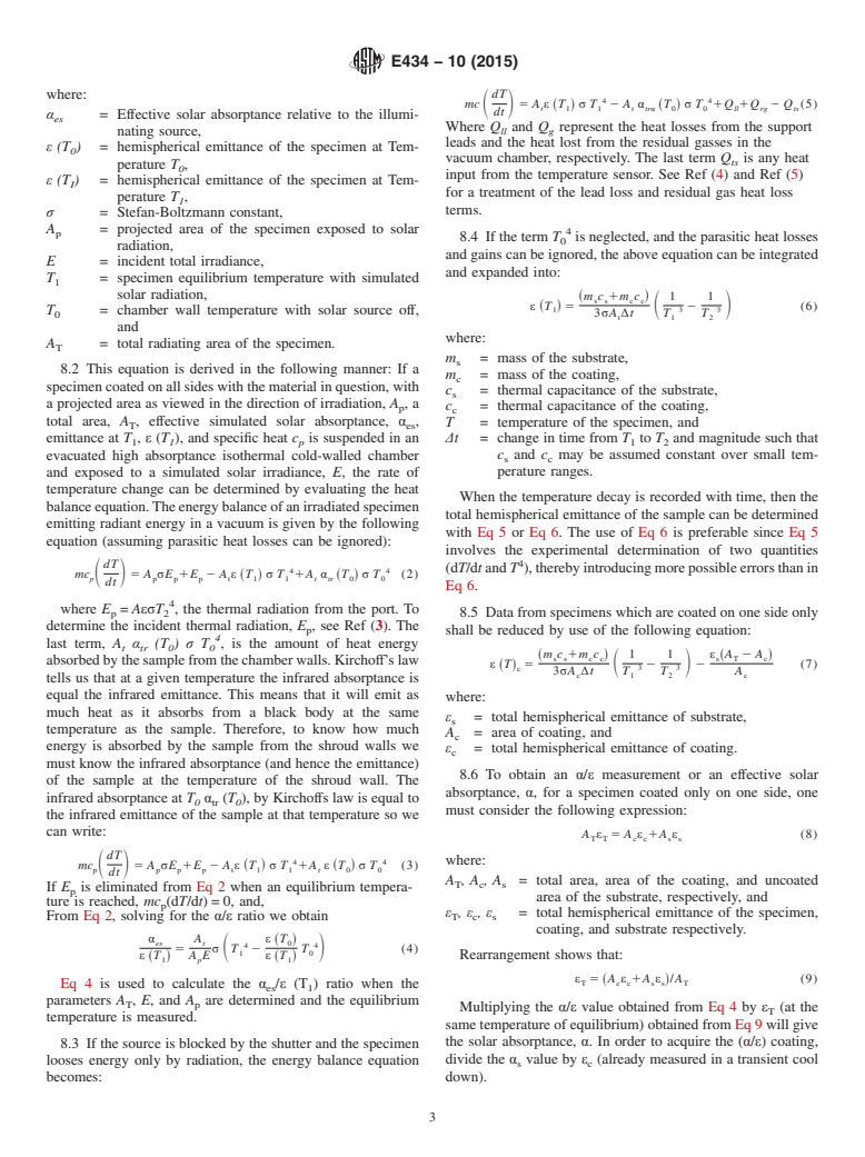
8.1 Calculate the α /ε (T ) ratio from the following equa-
es 1
tion:
4 α A ε T
~ !
The boldface numbers in parentheses refer to the list of references appended to es t 0
4 4
5 σ T 2 T (1)
S D
1 0
this method. ε T A E ε T
~ ! ~ !
1 p 1
E434 − 10 (2015)
where: dT
4 4
mc 5 A ε ~T ! σ T 2 A α ~T ! σ T 1Q 1Q 2 Q (5)
S D
t 1 1 t trα 0 0 ll rg ts
dt
α = Effective solar absorptance relative to the illumi-
es
Where Q and Q represent the heat losses from the support
ll g
nating source,
leads and the heat lost from the residual gasses in the
ε (T ) = hemispherical emittance of the specimen at Tem-
vacuum chamber, respectively. The last term Q is any heat
ts
perature T ,
input from the temperature sensor. See Ref (4) and Ref (5)
ε (T ) = hemispherical emittance of the specimen at Tem-
I
for a treatment of the lead loss and residual gas heat loss
perature T ,
terms.
σ = Stefan-Boltzmann constant,
A = projected area of the specimen exposed to solar
p
8.4 If the term T is neglected, and the parasitic heat losses
radiation,
and gains can be ignored, the above equation can be integrated
E = incident total irradiance,
and expanded into:
T = specimen equilibrium temperature with simulated
solar radiation, m c 1m c 1 1
~ !
s s c c
ε ~T ! 5 2 (6)
S D
1 3 3
T = chamber wall temperature with solar source off,
3σA ∆t T T
t 1 2
and
where:
A = total radiating area of the specimen.
T
m = mass of the substrate,
s
8.2 This equation is derived in the following manner: If a
m = mass of the coating,
c
specimencoatedonallsideswiththematerialinquestion,with
c = thermal capacitance of the substrate,
s
a projected area as viewed in the direction of irradiation, A,a
c = thermal capacitance of the coating,
p
c
total area, A , effective simulated solar absorptance, α ,
T = temperature of the specimen, and
T es
∆t = change in time from T to T and magnitude such that
emittance at T , ε (T ), and specific heat c is suspended in an
1 1 p 1 2
evacuated high absorptance isothermal cold-walled chamber c and c may be assumed constant over small tem-
s c
perature ranges.
and exposed to a simulated solar irradiance, E, the rate of
temperature change can be determined by evaluating the heat
When the temperature decay is recorded with time, then the
balanceequation.Theenergybalanceofanirradiatedspecimen
total hemispherical emittance of the sample can be determined
emitting radiant energy in a vacuum is given by the following
with Eq 5 or Eq 6. The use of Eq 6 is preferable since Eq 5
equation (assuming parasitic heat losses can be ignored):
involves the experimental determination of two quantities
dT
(dT/dtand T ),therebyintroducingmorepossibleerrorsthanin
4 4
mc 5 A σE 1E 2 A ε T σ T 1A α T σ T (2)
S D ~ ! ~ !
p p p p t 1 1 t tr 0 0
dt
Eq 6.
where E = AεσT , the thermal radiation from the port. To
p 2 8.5 Data from specimens which are coated on one side only
determine the incident thermal radiation, E , see Ref (3). The
p shall be reduced by use of the following equation:
last term, A α (T ) σ T , is the amount of heat energy
t tr 0 0
m c 1m c 1 1 ε A 2 A
~ ! ~ !
s s c c s T c
absorbedbythesamplefromthechamberwalls.Kirchoff’slaw
ε ~T! 5 2 2 (7)
S 3 3 D
c
3σA ∆t T T A
c 1 2 c
tells us that at a given temperature the infrared absorptance is
equal the infrared emittance. This means that it will emit as
where:
much heat as it absorbs from a black body at the same
ε = total hemispherical emittance of substrate,
s
temperature as the sample. Therefore, to know how much
A = area of coating, and
c
energy is absorbed by the sample from the shroud walls we
ε = total hemispherical emittance of coating.
c
must know the infrared absorptance (and hence the emittance)
8.6 To obtain an α/ε measurement or an effective solar
of the sample at the temperature of the shroud wall. The
absorptance, α, for a specimen coated only on one side, one
infrared absorptance at T α (T ), by Kirchoffs law is equal to
0 tr 0
must consider the following expression:
the infrared emittance of the sample at that temperature so we
can write:
A ε 5 A ε 1A ε (8)
T T c c s s
dT
4 4 where:
mc 5 A σE 1E 2 A ε T σ T 1A ε T σ T (3)
S D ~ ! ~ !
p p p p t 1 1 t 0 0
dt
A ,A ,A = total area, area of the coating, and uncoated
T c s
If E is eliminated from Eq 2 when an equilibrium tempera-
p
area of the substrate, respectively, and
ture is reached, mc (dT/dt)=0, and,
p
ε , ε , ε = total hemispherical emittance of the specimen,
From Eq 2, solving for the α/ε ratio we obtain T c s
coating, and substrate respectively.
α A ε T
~ !
es t 0
4 4
5 σ T 2 T (4)
S D
1 0
ε ~T ! A E ε ~T ! Rearrangement shows that:
1 p 1
ε 5 A ε 1A ε /A (9)
~ !
T c c s s T
Eq 4 is used to calculate the α /ε (T ) ratio when the
es 1
parameters A , E, and A are determined and the equilibrium
T p
Multiplying the α/
...
This document is not an ASTM standard and is intended only to provide the user of an ASTM standard an indication of what changes have been made to the previous version. Because
it may not be technically possible to adequately depict all changes accurately, ASTM recommends that users consult prior editions as appropriate. In all cases only the current version
of the standard as published by ASTM is to be considered the official document.
Designation: E434 − 10 E434 − 10 (Reapproved 2015)
Standard Test Method for
Calorimetric Determination of Hemispherical Emittance and
the Ratio of Solar Absorptance to Hemispherical Emittance
Using Solar Simulation
This standard is issued under the fixed designation E434; the number immediately following the designation indicates the year of
original adoption or, in the case of revision, the year of last revision. A number in parentheses indicates the year of last reapproval. A
superscript epsilon (´) indicates an editorial change since the last revision or reapproval.
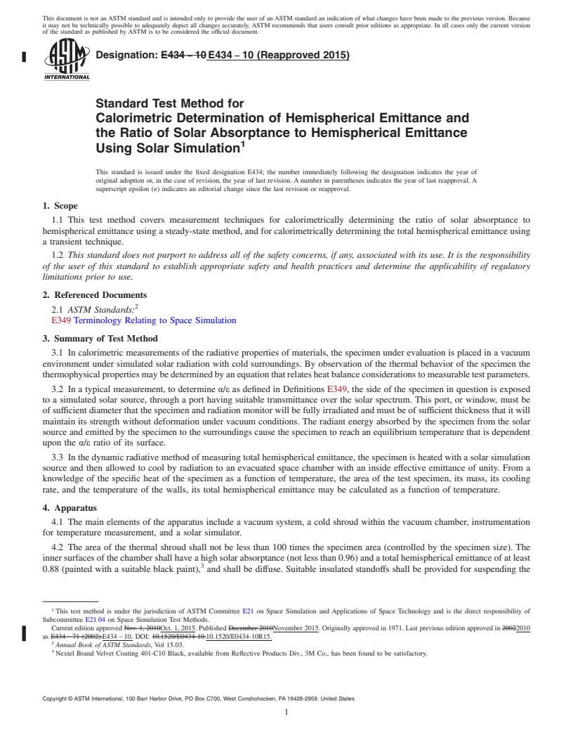
1. Scope
1.1 This test method covers measurement techniques for calorimetrically determining the ratio of solar absorptance to
hemispherical emittance using a steady-state method, and for calorimetrically determining the total hemispherical emittance using
a transient technique.
1.2 This standard does not purport to address all of the safety concerns, if any, associated with its use. It is the responsibility
of the user of this standard to establish appropriate safety and health practices and determine the applicability of regulatory
limitations prior to use.
2. Referenced Documents
2.1 ASTM Standards:
E349 Terminology Relating to Space Simulation
3. Summary of Test Method
3.1 In calorimetric measurements of the radiative properties of materials, the specimen under evaluation is placed in a vacuum
environment under simulated solar radiation with cold surroundings. By observation of the thermal behavior of the specimen the
thermophysical properties may be determined by an equation that relates heat balance considerations to measurable test parameters.
3.2 In a typical measurement, to determine α/ε as defined in Definitions E349, the side of the specimen in question is exposed
to a simulated solar source, through a port having suitable transmittance over the solar spectrum. This port, or window, must be
of sufficient diameter that the specimen and radiation monitor will be fully irradiated and must be of sufficient thickness that it will
maintain its strength without deformation under vacuum conditions. The radiant energy absorbed by the specimen from the solar
source and emitted by the specimen to the surroundings cause the specimen to reach an equilibrium temperature that is dependent
upon the α/ε ratio of its surface.
3.3 In the dynamic radiative method of measuring total hemispherical emittance, the specimen is heated with a solar simulation
source and then allowed to cool by radiation to an evacuated space chamber with an inside effective emittance of unity. From a
knowledge of the specific heat of the specimen as a function of temperature, the area of the test specimen, its mass, its cooling
rate, and the temperature of the walls, its total hemispherical emittance may be calculated as a function of temperature.
4. Apparatus
4.1 The main elements of the apparatus include a vacuum system, a cold shroud within the vacuum chamber, instrumentation
for temperature measurement, and a solar simulator.
4.2 The area of the thermal shroud shall not be less than 100 times the specimen area (controlled by the specimen size). The
inner surfaces of the chamber shall have a high solar absorptance (not less than 0.96) and a total hemispherical emittance of at least
0.88 (painted with a suitable black paint), and shall be diffuse. Suitable insulated standoffs shall be provided for suspending the
This test method is under the jurisdiction of ASTM Committee E21 on Space Simulation and Applications of Space Technology and is the direct responsibility of
Subcommittee E21.04 on Space Simulation Test Methods.
Current edition approved Nov. 1, 2010Oct. 1, 2015. Published December 2010November 2015. Originally approved in 1971. Last previous edition approved in 20022010
as E434 – 71 (2002).E434 – 10. DOI: 10.1520/E0434-10.10.1520/E0434-10R15.
Annual Book of ASTM Standards, Vol 15.03.
Nextel Brand Velvet Coating 401-C10 Black, available from Reflective Products Div., 3M Co., has been found to be satisfactory.
Copyright © ASTM International, 100 Barr Harbor Drive, PO Box C700, West Conshohocken, PA 19428-2959. United States
E434 − 10 (2015)
specimen. Thermocouple wires shall be connected to a vacuumtight fitting where the temperature of feedthrough is uniform.
Outside of the chamber, all thermocouples shall connect with a fixed cold junction.
−6
4.3 The chamber shall be evacuated to a pressure of 1 × 10 torr (0.1 mPa) or less at all times.
4.4 The walls of the inner shroud shall be in contact with coolant so that their temperature can be maintained uniform at all
times.
4.5 A shutter shall be provided in one end of the chamber which can be opened to admit a beam of radiant energy from a solar
simulator. When open, this shutter shall provide an aperture admitting the full simulator beam. When the shutter is closed, all rays
emitted by the specimen shall be intercepted by a blackened surface at the coolant temperature (the shutter must be at least
conductively coupled to the shroud).
4.6 The vacuum chamber shall be provided with a fused silica window large enough to admit the simulator beam and uniformly
irradiate the entire specimen projected area. This window shall have high transmittance through the solar spectrum wavelength
region. The chamber shall be provided with a vacuumtight sleeve for opening and closing the shutter and standard vacuum fittings
for gaging, bleeding, leak testing, and pumping. If low α/ε specimens are to be measured, the solid angle subtended by the port
from the specimen should be small (dependent upon desired accuracy). If flat specular specimens are to be measured, the port plane
should be canted with respect to the specimen plane to eliminate multiple reflections of the simulator beam. Multiple reflections
could result in as much as a 7 % apparent increase in α/ε.
4.7 The solar simulator should duplicate the extraterrestrial solar spectrum as closely as possible. A beam irradiance of at least
7000 W/m at the specimen plane shall be available from the solar simulator (;5 solar constants). This irradiance may be required
to raise the temperature of certain specimens to a desired level.
5. Coating Requirements
5.1 Any type of coating may be tested by this test method provided its structure remains stable in vacuum over the temperature
range of interest.
5.2 For high emittance specimens the accuracy of the measurements is increased if only one surface of the substrate is coated
with the specimen coating in question. The remaining area of the substrate shall be coated with a low emittance material of known
hemispherical emittance (such as evaporated aluminum or evaporated gold).
5.3 The thickness and density of the coating shall be measured and its heat capacity calculated from existing references (see
Refs (1) and (2)).
6. Specimen Preparation
6.1 The substrates used for the measurements described here shall be of a material whose specific heat as a function of
temperature can be found in standard references (for example, OFHC copper or a common aluminum alloy such as 6061-T6) (Ref
(1)).
6.2 The substrate shall be machined from flat stock and to a size proportioned to the working area of the chamber.
6.3 Each specimen shall be drilled with a set of holes, near the edge, through which suspension strings are to be inserted.
6.4 Each substrate shall be drilled with two small shallow holes in the back for thermocouples.
6.5 Ideally the back and sides of the substrate shall be buffed and polished and one uninsulated thermocouple inserted in the
back of the specimen (one wire in each hole). One of these wires shall be peened into each hole.
6.6 A low-emittance coating shall be applied to the back and sides of the substrate and to the thermocouple wires for several
inches at the specimen end.
6.7 The substrates shall be coated with the material in question. The coating shall be of sufficient thickness so as to be opaque.
(This will avoid any substrate effects.)
6.8 The specimens shall be suspended from the top of the shroud by means of thread or string. These strings shall be of small
diameter, low thermal conductivity, and low emittance in order to minimize heat losses through the leads.
6.9 An alternative method of specimen mounting (mass dependent) shall be to suspend the specimens by their own small wire
thermocouple leads. In this case the thermocouple holes shall be drilled as before but radially around the edge. The suspension
holes may also be eliminated in this case.
The boldface numbers in parentheses refer to the list of references appended to this method.
E434 − 10 (2015)
7. Procedure
7.1 Suspend the test specimen in the chamber normal to the incident solar radiation, but geometrically removed from the central
axis of the chamber so that radiation from the specimen to the chamber walls is not specularly reflected back to the specimen. Since
the chamber walls are designed to be cold and highly absorbing, first reflections from the walls are usually all that need be
considered.
7.2 Determine the simulated solar irradiance incident on the specimen with a suitable radiometric device such as a commercial
thermopile radiometer or a black monitor sample of known α/ε which may be suspended similarly to the test specimen within the
incident beam of simulated solar radiation. Take care in the latter case that the irradiance and spectral distribution of the incident
energy is the same for both specimen and monitor.
7.3 Then close the system and start the evacuation and cooling of the shroud (see Ref (3) for a typical system). Maintain a
−6
pressure of 1 × 10 torr (0.1 mPa) or less and the walls of the chamber must be at coolant temperature. Record the specimen,
monitor, and shroud temperatures.
7.4 When the specimen has reached thermal equilibrium, that is, when the specimen temperature becomes constant with
constant surrounding conditions, shut off the solar simulator. When specimens of large thermal mass are used, carefully evaluate
the ΔT/Δt = 0 conditions, that is, the Δt chosen should be dependent on the specimen time constant.
7.5 Close the moveable door in the shroud and allow the specimens to cool to a desired temperature. Measure the specimen
temperature as a function of time and calculate the rates of change of the temperature.
8. Calculation
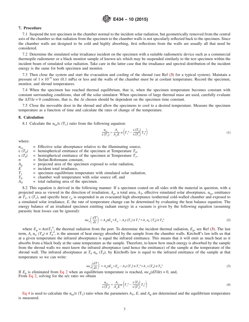
8.1 Calculate the α /ε (T ) ratio from the following equation:
es 1
α A ε T
~ !
es t 0
4 4
5 σ T 2 T (1)
S D
1 0
ε ~T ! A E ε ~T !
1 p 1
where:
α = Effective solar absorptance relative to the illuminating source,
es
ε (T ) = hemispherical emittance of the specimen at Temperature T ,
0 0
ε (T ) = hemispherical emittance of the specimen at Temperature T ,
I 1
σ = Stefan-Boltzmann constant,
A = projected area of the specimen exposed to solar radiation,
p
E = incident total irradiance,
T = specimen equilibrium temperature with simulated solar radiation,
T = chamber wall temperature with solar source off, and
A = total radiating area of the specimen.
T
8.2 This equation is derived in the following manner: If a specimen coated on all sides with the material in question, with a
projected area as viewed in the direction of irradiation, A , a total area, A , effective simulated solar absorptance, α , emittance
p T es
at T , ε (T ), and specific heat c is suspended in an evacuated high absorptance isothermal cold-walled chamber and exposed to
1 1 p
a simulated solar irradiance, E, the rate of temperature change can be determined by evaluating the heat balance equation. The
energy balance of an irradiated specimen emitting radiant energy in a vacuum is given by the following equation (assuming
parasitic heat losses can be ignored):
dT
4 4
mc 5 A σE 1E 2 A ε ~T ! σ T 1A α ~T ! σ T (2)
S D
p p p p t 1 1 t tr 0 0
dt
where E = AεσT , the thermal radiation from the port. To determine the incident thermal radiation, E , see Ref (3). The last
p 2 p
term, A α (T ) σ T , is the amount of heat energy absorbed by the sample from the chamber walls. Kirchoff’s law tells us that
t tr 0 0
at a given temperature the infrared absorptance is equal the infrared emittance. This means that it will emit as much heat as it
absorbs from a black body at the same temperature as the sample. Therefore, to know how much energy is absorbed by the sample
from the shroud walls we must know the infrared absorptance (and hence the emittance) of the sample at the temperature of the
shroud wall. The infrared absorptance at T α (T ), by Kirchoffs law is equal to the infrared emittance of the sample at that
0 tr 0
temperature so we can write:
dT
4 4
mc 5 A σE 1E 2 A ε T σ T 1A ε T σ T (3)
S D ~ ! ~ !
p p p p t 1 1 t 0 0
dt
If E is eliminated from Eq 2 when an equilibrium temperature is reached, mc (dT/dt) = 0, and,
p p
From Eq 2, solving for the α/ε ratio we obtain
α A ε ~T !
es t 0
4 4
5 σ T 2 T (4)
S D
1 0
ε T A E ε T
~ ! ~ !
1 p 1
Eq 4 is used to calculate the α /ε (T ) ratio when the parameters A , E, and A are determined and the equilibrium temperature
es 1 T p
is measured.
E434 − 10 (2015)
8.3 If the source is blocked by the shutter and the specimen looses energy only by radiation, the energy balance equation
becomes:
dT
4 4
mc 5 A ε ~T ! σ T 2 A α ~T ! σ T 1Q 1Q 2 Q (5)
S D
t 1 1 t trα 0 0 ll rg ts
dt
Where Q and Q represent the heat losses from the support leads and the heat lost from the residual gasses in the vacuum
ll g
chamber, respectively. The last term Q is any heat input from the temperature sensor. See Ref (4) and Ref (5) for a treatment
ts
of the lead loss and residual gas heat loss terms.
8.4 If the term T is neglected, and the parasitic heat losses and gains can be ignored, the above equation can be integrated and
expanded into:
m c 1m c 1 1
~ !
s s c c
ε T 5 2 (6)
~ ! S D
1 3 3
3σA Δt T T
t 1 2
where:
m = mass of the substrate,
s
m = mass of the coating,
c
c = thermal capacitance of the substrate,
s
c = thermal capacitance of the coating,
c
T = temperature of the specimen, and
Δt = change in time from T to T and magnitude such that c and c may be assumed constant over small temperature ranges.
1 2 s c
When the temperature decay is recorded with time, then the total hemispherical emittance of the sample can be determined with
Eq 5 or Eq 6. The use of Eq 6 is preferable since Eq 5 involves the experimental determination of two quantities (dT/dt and T ),
thereby introducing more possible errors than in Eq 6.
8.
...
Questions, Comments and Discussion
Ask us and Technical Secretary will try to provide an answer. You can facilitate discussion about the standard in here.