


ASTM D5001-10(2014)
(Test Method)Standard Test Method for Measurement of Lubricity of Aviation Turbine Fuels by the Ball-on-Cylinder Lubricity Evaluator (BOCLE)
Standard Test Method for Measurement of Lubricity of Aviation Turbine Fuels by the Ball-on-Cylinder Lubricity Evaluator (BOCLE)
SIGNIFICANCE AND USE
5.1 Wear due to excessive friction resulting in shortened life of engine components such as fuel pumps and fuel controls has sometimes been ascribed to lack of lubricity in an aviation fuel.
5.2 The relationship of test results to aviation fuel system component distress due to wear has been demonstrated for some fuel/hardware combinations where boundary lubrication is a factor in the operation of the component.
5.3 The wear scar generated in the ball-on-cylinder lubricity evaluator (BOCLE) test is sensitive to contamination of the fluids and test materials, the presence of oxygen and water in the atmosphere, and the temperature of the test. Lubricity measurements are also sensitive to trace materials acquired during sampling and storage. Containers specified in Practice D4306 shall be used.
5.4 The BOCLE test method may not directly reflect operating conditions of engine hardware. For example, some fuels that contain a high content of certain sulfur compounds can give anomalous test results.
SCOPE
1.1 This test method covers assessment of the wear aspects of the boundary lubrication properties of aviation turbine fuels on rubbing steel surfaces.
1.1.1 This test method incorporates two procedures, one using a semi-automated instrument and the second a fully automated instrument. Either of the two instruments may be used to carry out the test.
1.2 The values stated in SI units are to be regarded as standard. No other units of measurement are included in this standard.
1.3 This standard does not purport to address the safety concerns, if any, associated with its use. It is the responsibility of the user of this standard to establish appropriate safety and health practices and determine the applicability of regulatory limitations prior to use.
General Information
Buy Standard
Standards Content (Sample)
NOTICE: This standard has either been superseded and replaced by a new version or withdrawn.
Contact ASTM International (www.astm.org) for the latest information
Designation: D5001 − 10 (Reapproved 2014) An American National Standard
Standard Test Method for
Measurement of Lubricity of Aviation Turbine Fuels by the
Ball-on-Cylinder Lubricity Evaluator (BOCLE)
This standard is issued under the fixed designation D5001; the number immediately following the designation indicates the year of
original adoption or, in the case of revision, the year of last revision.Anumber in parentheses indicates the year of last reapproval.A
superscript epsilon (´) indicates an editorial change since the last revision or reapproval.
This standard has been approved for use by agencies of the U.S. Department of Defense.
1. Scope 2.3 American Iron and Steel Institute Standard:
AISI E-52100Chromium Alloy Steel
1.1 This test method covers assessment of the wear aspects
2.4 ISO Standard:
of the boundary lubrication properties of aviation turbine fuels
ISO 3290-1:2008 Rolling bearings -- Balls -- Part 1: Steel
on rubbing steel surfaces.
balls
1.1.1 This test method incorporates two procedures, one
2.5 Society of Automotive Engineers Standard:
using a semi-automated instrument and the second a fully
SAE 8720Steel
automated instrument. Either of the two instruments may be
used to carry out the test.
3. Terminology
1.2 The values stated in SI units are to be regarded as
3.1 Definitions:
standard. No other units of measurement are included in this
3.1.1 lubricity—qualitative term describing the ability of a
standard.
fluid to minimize friction between, and damage to, surfaces in
1.3 This standard does not purport to address the safety
relative motion under load.
concerns, if any, associated with its use. It is the responsibility
3.1.1.1 Discussion—In this test method, the lubricity of a
of the user of this standard to establish appropriate safety and
fluid is defined in terms of a wear scar, in millimeters,
health practices and determine the applicability of regulatory
produced on a loaded stationary ball from contact with a
limitations prior to use.
fluid-wetted rotating cylindrical test ring operating under
closely defined and controlled conditions.
2. Referenced Documents
3.1.2 wear scar—in the liquid fuels industry, average diam-
eter of a worn and abraded area, measured in two specified
2.1 ASTM Standards:
directions, produced on a test ball under defined conditions.
D4306Practice for Aviation Fuel Sample Containers for
3.1.2.1 Discussion—The wear scar generated by Test
Tests Affected by Trace Contamination
Method D5001 is often referred to as the BOCLE wear scar.
D6708Practice for StatisticalAssessment and Improvement
of Expected Agreement Between Two Test Methods that
3.2 Abbreviations:
Purport to Measure the Same Property of a Material
3.2.1 BOCLE—Ball On Cylinder Lubricity Evaluator
2.2 Military Specification:
3.2.2 HRC—Rockwell Hardness “C” scale.
MIL-I-25017Inhibitor, Corrosion/Lubricity Improver, Fuel
3.2.3 WSD—Wear Scar Diameter
Soluble
4. Summary of Test Method
4.1 Thefluidundertestisplacedinatestreservoirinwhich
This test method is under the jurisdiction of ASTM Committee D02 on
atmospheric air is maintained at 10% relative humidity. A
Petroleum Products, Liquid Fuels, and Lubricants and is the direct responsibility of
non-rotatingsteelballisheldinaverticallymountedchuckand
Subcommittee D02.J0.04 on Additives and Electrical Properties.
forced against the outside diameter of an axially mounted
Current edition approved Oct. 1, 2014. Published November 2014. Originally
approved in 1989. Last previous edition approved in 2010 as D5001–10. DOI:
10.1520/D5001-10R14.
2 4
For referenced ASTM standards, visit the ASTM website, www.astm.org, or Available from American Iron and Steel Institute (AISI), 1140 Connecticut
contact ASTM Customer Service at service@astm.org. For Annual Book of ASTM Ave., NW, Suite 705, Washington, DC 20036, http://www.steel.org.
Standards volume information, refer to the standard’s Document Summary page on Available from International Organization for Standardization (ISO), 1, ch. de
the ASTM website. la Voie-Creuse, Case postale 56, CH-1211, Geneva 20, Switzerland, http://
Available from Standardization Documents Order Desk, DODSSP, Bldg. 4, www.iso.ch.
Section D, 700 Robbins Ave., Philadelphia, PA 19111-5098, http:// Available from Society of Automotive Engineers (SAE), 400 Commonwealth
www.dodssp.daps.mil. Dr., Warrendale, PA 15096-0001, http://www.sae.org.
Copyright © ASTM International, 100 Barr Harbor Drive, PO Box C700, West Conshohocken, PA 19428-2959. United States
D5001 − 10 (2014)
TABLE 1 Standard Operating Conditions
cylindrical steel ring with an applied load. The test ring is
rotated at a fixed speed while being partially immersed in the Fluid Volume 50 ± 1.0 mL
Fluid Temperature 25 ± 1°C
fluid reservoir. This maintains the ring in a wet condition and
Conditioned Air 10 ± 0.2 % relative humidity at 25 ± 1°C
continuously transports the test fluid to the ball/ring interface.
Fluid pretreatment 0.50 L/min flowing through and 3.3 L/min
over the fluid for 15 min
The wear scar generated on the test ball is a measure of the
Fluid test conditions 3.8 L/min flowing over the fluid
lubricatingpropertyofthefluid.Forwearscardiameter(WSD)
Applied Load 1000 g (500 g weight) (± l g)
calibration and standardization, see Section 10. Cylinder Rotational Speed 240±1rpm
Test Duration 30 ± 0.1 min
5. Significance and Use
5.1 Wearduetoexcessivefrictionresultinginshortenedlife
7. Reagents and Materials
ofenginecomponentssuchasfuelpumpsandfuelcontrolshas
7.1 Test Ring, of SAE 8720 steel, having a Rockwell
sometimesbeenascribedtolackoflubricityinanaviationfuel.
hardness “C” scale, (HRC) number of 58 to 62 and a surface
7,10
5.2 The relationship of test results to aviation fuel system
finishof0.56to0.71µmrootmeansquare. Thedimensions
component distress due to wear has been demonstrated for
are given in Fig. 1.
some fuel/hardware combinations where boundary lubrication
7.2 Test Balls, chrome alloy steel, made fromAISI standard
is a factor in the operation of the component.
steelNo.E-52100,withadiameterof12.7mm,Grade5to10.
TheballsaredescribedinISO3290-1:2008.TheHRCshallbe
5.3 Thewearscargeneratedintheball-on-cylinderlubricity
64 to 66, a closer limit than is found in the ISO requirement.
evaluator (BOCLE) test is sensitive to contamination of the
fluids and test materials, the presence of oxygen and water in
7.3 Additional Equipment—Details of additional items of
the atmosphere, and the temperature of the test. Lubricity
test equipment specific to each test method are given in the
measurements are also sensitive to trace materials acquired
appropriate annex.
during sampling and storage. Containers specified in Practice
7.4 Compressed Air (Warning—Compressed gas under
D4306 shall be used.
high pressure. Use with extreme caution in the presence of
combustible material, since the autoignition temperatures of
5.4 The BOCLE test method may not directly reflect oper-
most organic compounds in air are drastically reduced at
ating conditions of engine hardware. For example, some fuels
elevated pressures. See A3.1.), containing less than 0.1 ppm
that contain a high content of certain sulfur compounds can
hydrocarbons and 50 ppm water.
give anomalous test results.
6. Apparatus
Thesolesourceofsupplyoftheapparatusknowntothecommitteeatthistime
is (for the semi-automatic method) Test Rings Part No. F25061, Falex Corp., 2055
6.1 For details of the Ball-On-Cylinder Lubricity Evaluator
Comprehensive Drive,Aurora, IL 60505 and (for the fully automatic method) Test
(BOCLE), apparatus required for each method see: Annex A1
Rings, Part No. ABSRING, PCS Instruments, 78 Stanley Gardens, London, W3
for the semi-automatic method, Annex A2 for the fully
7SZ, U.K.
automatic method.
6.2 Microscope,capableof100×magnificationandsuitable
of measuring the wear scar on the ball to the nearest 0.01 mm.
6.2.1 Method of Measuring the Wear Scar—This may be
either a Glass Slide Micrometer, with a scale ruled in 0.01 mm
7,8
divisions, oradigitalmicrometerandslideassembly,having
7,9
a resolution of at least 0.01 mm.
6.3 Cleaning Bath—Ultrasonic seamless stainless steel tank
with a capacity of 1.9 L and a cleaning power of 40W.
6.4 The test requirements are listed in Table 1.
If you are aware of alternative suppliers, please provide this information to
ASTM International Headquarters. Your comments will receive careful consider-
ation at a meeting of the responsible technical committee, which you may attend.
The sole source of supply of the apparatus known to the committee at this time
is Catalog No. 31-16-99 from Bausch and Lomb, Inc., Bausch & Lomb World
Headquarters,OneBausch&LombPlace,Rochester,NY14604-2701.Acertificate
of traceability from the National Institute of Standards andTechnology is available.
The sole source of supply of the apparatus known to the committee at this time
is Microscope part number ABSMIC from PCS Instruments, 78 Stanley Gardens,
London, W3 7SZ, U.K. A certificate of traceability from the National Institute of
Standards and Technology is available. FIG. 1 Ball-on-Cylinder Test Ring
D5001 − 10 (2014)
7.5 Desiccator, containing a non-indicating drying agent, 8.1.2.1 Place balls in 300 mL beaker. Transfer a sufficient
capable of storing test rings, balls, and hardware. volume ofa1to1 mixture of isooctane and isopropyl alcohol
tothebeakersuchthatthetestballsarecompletelycoveredby
7.6 Gloves, clean, lint-free, cotton, disposable.
the cleaning solvent.
7.7 Wiper, wiping tissue, light duty, lint free, hydrocarbon
NOTE 2—Approximately a five-day supply can be processed at one
free, disposable.
time.
7.8 Isooctane (Warning—Extremely flammable. Harmful
8.1.2.2 Placebeakerinultrasoniccleanerandturnonfor15
if inhaled. Vapors may cause flash fires. See A3.2.), conform-
min.
ing to American Chemical Society (ACS) Reagent/General
8.1.2.3 Repeat the cleaning cycle of 8.1.2.2 with a clean
Purpose Reagent (GPR) grade standards, 95 % purity
beaker and fresh solvent.
minimum, 2,2,4-trimethylpentane.
8.1.2.4 Removeandrinsewithisooctane,dry,andrinsewith
7.9 Isopropyl Alcohol (Warning—Flammable. See A3.3.),
acetone.
conforming to ACS Reagent/GPR grade standards.
8.1.2.5 Dry and store in a desiccator.
7.10 Acetone (Warning—Extremely flammable. Vapors 8.1.3 Reservoir, Reservoir Cover, Ball Chuck, Lock Ring,
may cause flash fire. See A3.4.), conforming toACS Reagent/
Mandrel Assembly (Method A, Semi Automatic Method) Test
GPR grade standards. Ring Assembly (Method B, Fully Automatic Method), and all
other parts which come into direct contact with the test fuel
7.11 Reference Fluids:
(refer to the appropriate annex).
7.11.1 Fluid A—A mixture shall contain 30 mg/kg of a
8.1.3.1 Rinse with isooctane.
specific fuel soluble corrosion inhibitor/lubricity improver
7,11
8.1.3.2 Clean in an ultrasonic cleaner with a 1:1 mixture of
conformingtoMIL-I-25017 (Warning—Flammable.Vapor
7 ,12
isooctane and isopropyl alcohol for 5 min.
harmful. See A3.5.), in fluid B (Warning—Flammable.
8.1.3.3 Removeandrinsewithisooctane,dry,andrinsewith
Vapor harmful. See A3.5.).
acetone.
7.11.2 Fluid B—Shall be a narrow-cut isoparaffinic solvent.
7,12
8.1.3.4 Store in a desiccator until required.
(Warning—Flammable. Vapor harmful. See A3.5.)
8.1.4 Hardware:
7.11.3 The reference fluids shall be stored in epoxy lined
8.1.4.1 The hardware and utensils, that is, any part that
containers or borosilicate glass bottles with aluminum foil or
comesincontactwiththetestfluidshallbecleanedbywashing
PTFE lined insert caps. Borosilicate glass bottles shall be
thoroughly with isooctane and wiped with a wiper.
stored in a dark area.
8.1.4.2 Store parts in desiccator when not in use.
8.1.5 After Test:
8. Sampling, Test Specimens, and Test Units
8.1.5.1 Remove reservoir and test ring.
8.1 Cleaning of Apparatus and Test Components:
8.1.5.2 Disassemble components and clean in an ultrasonic
8.1.1 Test Rings, as Received:
cleaner usinga1to1 mixture of isooctane and isopropyl
8.1.1.1 The test rings shall be partially stripped of any
alcohol for 5 min. Rinse with isooctane, dry, and rinse with
protective coatings by manually rubbing them with rags or
acetone. Reassemble components.
paper towels saturated with isooctane.
8.1.5.3 Dry and store in a desiccator.
8.1.1.2 Place partially cleaned rings in a clean 500 mL
beaker. Transfer a sufficient volume ofa1to1 mixture of
NOTE 3—When testing the same fluid, it is permissible to clean the
isooctane (2,2,4-trimethyl pentane) and isopropyl alcohol to
reservoir by hand. The reservoir is rinsed with isooctane. Wipe with
disposable wiper to remove residual fuel related deposits and test debris.
the beaker such that the test rings are completely covered.
The reservoir is rinsed again with isooctane. Dry and final rinse with
8.1.1.3 Placebeakerinultrasoniccleanerandturnonfor15
acetone, dry.
min.
8.1.5.4 Store parts in desiccator when not in use.
8.1.1.4 Remove test rings and repeat ultrasonic cleaning
8.1.5.5 Semi-Automatic (Method A) Only—Care shall be
cycle of 8.1.1.3 with a clean beaker and fresh solvents.
taken to ensure that the fuel aeration tube is rinsed and dried
8.1.1.5 Handle all clean test rings with clean forceps or
during the cleaning procedure. Store parts in desiccator when
disposable gloves. Remove test rings from beaker and rinse
not in use.
with isooctane, dry, and rinse with acetone.
NOTE 1—Drying operations can be accomplished using a compressed
9. Preparation of Apparatus
air jet at 140 to 210 kPa pressure.
9.1 Use the following procedures, where applicable:
8.1.1.6 Dry and store in a desiccator.
Annex A1 for the semi-automatic method.
8.1.2 Test Balls, as Received.
Annex A2 for the fully automatic method.
10. Calibration and Standardization
Thesolesourceofsupplyoftheapparatusknowntothecommitteeatthistime
isDCI-4AAdditive,InnospecFuelSpecialties,8375SouthWillowStreet,Littleton, 10.1 Visually inspect test balls before each test. Discard
CO 80124.
balls that exhibit pits, corrosion, or surface abnormalities.
Thesolesourceofsupplyoftheapparatusknowntothecommitteeatthistime
isISOPARMSolvent,ExxonCompany,USA,P.O.Box2180,Houston,TX77001. 10.2 Reference Fluids:
D5001 − 10 (2014)
10.2.1 Conduct three tests on each new batch of the refer- 12.1.2 Focus the microscope and adjust the stage such that
ence fluids in accordance with Section 11 using a test ring wear scar is centered within the field of view.
previously standardized by reference fluid testing. 12.1.3 Align the wear scar to either a divisional point of
10.2.2 Repeatthethreetestsifthewearscardiametersdiffer reference on the numerical scale with the mechanical stage
by more than 0.04 mm for Reference FluidAor by more than controls, or the c
...
This document is not an ASTM standard and is intended only to provide the user of an ASTM standard an indication of what changes have been made to the previous version. Because
it may not be technically possible to adequately depict all changes accurately, ASTM recommends that users consult prior editions as appropriate. In all cases only the current version
of the standard as published by ASTM is to be considered the official document.
Designation: D5001 − 10 D5001 − 10 (Reapproved 2014) An American National Standard
Standard Test Method for
Measurement of Lubricity of Aviation Turbine Fuels by the
Ball-on-Cylinder Lubricity Evaluator (BOCLE)
This standard is issued under the fixed designation D5001; the number immediately following the designation indicates the year of
original adoption or, in the case of revision, the year of last revision. A number in parentheses indicates the year of last reapproval. A
superscript epsilon (´) indicates an editorial change since the last revision or reapproval.
This standard has been approved for use by agencies of the U.S. Department of Defense.
1. Scope*Scope
1.1 This test method covers assessment of the wear aspects of the boundary lubrication properties of aviation turbine fuels on
rubbing steel surfaces.
1.1.1 This test method incorporates two procedures, one using a semi-automated instrument and the second a fully automated
instrument. Either of the two instruments may be used to carry out the test.
1.2 The values stated in SI units are to be regarded as standard. No other units of measurement are included in this standard.
1.3 This standard does not purport to address the safety concerns, if any, associated with its use. It is the responsibility of the
user of this standard to establish appropriate safety and health practices and determine the applicability of regulatory limitations
prior to use.
2. Referenced Documents
2.1 ASTM Standards:
D4306 Practice for Aviation Fuel Sample Containers for Tests Affected by Trace Contamination
D6708 Practice for Statistical Assessment and Improvement of Expected Agreement Between Two Test Methods that Purport
to Measure the Same Property of a Material
2.2 Military Specification:
MIL-I-25017 Inhibitor, Corrosion/Lubricity Improver, Fuel Soluble
2.3 American Iron and Steel Institute Standard:
AISI E-52100 Chromium Alloy Steel
2.4 ISO Standard:
ISO 3290-1:2008 Rolling bearings -- Balls -- Part 1: Steel balls
2.5 Society of Automotive Engineers Standard:
SAE 8720 Steel
3. Terminology
3.1 Definitions:
3.1.1 lubricity—qualitative term describing the ability of a fluid to minimize friction between, and damage to, surfaces in
relative motion under load.
This test method is under the jurisdiction of ASTM Committee D02 on Petroleum Products Products, Liquid Fuels, and Lubricants and is the direct responsibility of
Subcommittee D02.J0.04 on Additives and Electrical Properties.
Current edition approved July 1, 2010Oct. 1, 2014. Published July 2010November 2014. Originally approved in 1989. Last previous edition approved in 20082010 as
D5001D5001 – 10.–08. DOI: 10.1520/D5001-10.10.1520/D5001-10R14.
For referenced ASTM standards, visit the ASTM website, www.astm.org, or contact ASTM Customer Service at service@astm.org. For Annual Book of ASTM Standards
volume information, refer to the standard’s Document Summary page on the ASTM website.
Available from Standardization Documents Order Desk, DODSSP, Bldg. 4, Section D, 700 Robbins Ave., Philadelphia, PA 19111-5098, http://www.dodssp.daps.mil.
Available from American Iron and Steel Institute (AISI), 1140 Connecticut Ave., NW, Suite 705, Washington, DC 20036, http://www.steel.org.
Available from International Organization for Standardization (ISO), 1, ch. de la Voie-Creuse, Case postale 56, CH-1211, Geneva 20, Switzerland, http://www.iso.ch.
Available from Society of Automotive Engineers (SAE), 400 Commonwealth Dr., Warrendale, PA 15096-0001, http://www.sae.org.
3.1.1.1 Discussion—
*A Summary of Changes section appears at the end of this standard
Copyright © ASTM International, 100 Barr Harbor Drive, PO Box C700, West Conshohocken, PA 19428-2959. United States
D5001 − 10 (2014)
In this test method, the lubricity of a fluid is defined in terms of a wear scar, in millimeters, produced on a loaded stationary ball
from contact with a fluid-wetted rotating cylindrical test ring operating under closely defined and controlled conditions.
3.1.2 wear scar—in the liquid fuels industry, average diameter of a worn and abraded area, measured in two specified directions,
produced on a test ball under defined conditions.
3.1.2.1 Discussion—
The wear scar generated by Test Method D5001 is often referred to as the BOCLE wear scar.
3.2 Abbreviations:
3.2.1 BOCLE—Ball On Cylinder Lubricity Evaluator
3.2.2 HRC—Rockwell Hardness “C” scale.
3.2.3 WSD—Wear Scar Diameter
4. Summary of Test Method
4.1 The fluid under test is placed in a test reservoir in which atmospheric air is maintained at 10 % relative humidity. A
non-rotating steel ball is held in a vertically mounted chuck and forced against the outside diameter of an axially mounted
cylindrical steel ring with an applied load. The test ring is rotated at a fixed speed while being partially immersed in the fluid
reservoir. This maintains the ring in a wet condition and continuously transports the test fluid to the ball/ring interface. The wear
scar generated on the test ball is a measure of the lubricating property of the fluid. For wear scar diameter (WSD) calibration and
standardization, see Section 10.
5. Significance and Use
5.1 Wear due to excessive friction resulting in shortened life of engine components such as fuel pumps and fuel controls has
sometimes been ascribed to lack of lubricity in an aviation fuel.
5.2 The relationship of test results to aviation fuel system component distress due to wear has been demonstrated for some
fuel/hardware combinations where boundary lubrication is a factor in the operation of the component.
5.3 The wear scar generated in the ball-on-cylinder lubricity evaluator (BOCLE) test is sensitive to contamination of the fluids
and test materials, the presence of oxygen and water in the atmosphere, and the temperature of the test. Lubricity measurements
are also sensitive to trace materials acquired during sampling and storage. Containers specified in Practice D4306 shall be used.
5.4 The BOCLE test method may not directly reflect operating conditions of engine hardware. For example, some fuels that
contain a high content of certain sulfur compounds can give anomalous test results.
6. Apparatus
6.1 For details of the Ball-On-Cylinder Lubricity Evaluator (BOCLE), apparatus required for each method see: Annex A1 for
the semi-automatic method, Annex A2 for the fully automatic method.
6.2 Microscope, capable of 100× magnification and suitable of measuring the wear scar on the ball to the nearest 0.01 mm.
6.2.1 Method of Measuring the Wear Scar—This may be either a Glass Slide Micrometer, with a scale ruled in 0.01 mm
7,8 7,9
divisions, or a digital micrometer and slide assembly, having a resolution of at least 0.01 mm.
6.3 Cleaning Bath—Ultrasonic seamless stainless steel tank with a capacity of 1.9 L and a cleaning power of 40W.
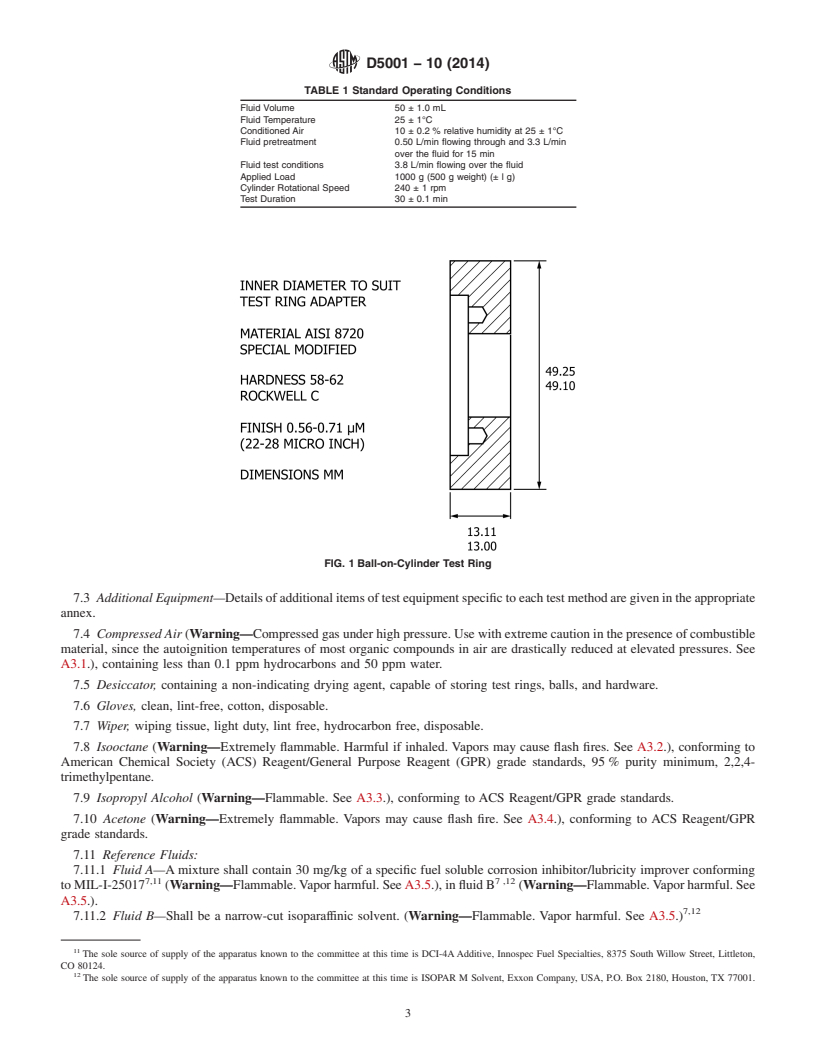
6.4 The test requirements are listed in Table 1.
7. Reagents and Materials
7.1 Test Ring, of SAE 8720 steel, having a Rockwell hardness “C” scale, (HRC) number of 58 to 62 and a surface finish of 0.56
7,10
to 0.71 μm root mean square. The dimensions are given in Fig. 1.
7.2 Test Balls, chrome alloy steel, made from AISI standard steel No. E-52100, with a diameter of 12.7 mm, Grade 5 to 10. The
balls are described in ISO 3290-1:2008. The HRC shall be 64 to 66, a closer limit than is found in the ISO requirement.
If you are aware of alternative suppliers, please provide this information to ASTM International Headquarters. Your comments will receive careful consideration at a
meeting of the responsible technical committee, which you may attend.
The sole source of supply of the apparatus known to the committee at this time is Catalog No. 31-16-99 from Bausch and Lomb, Inc., Bausch & Lomb World
Headquarters, One Bausch & Lomb Place, Rochester, NY 14604-2701. A certificate of traceability from the National Institute of Standards and Technology is available.
The sole source of supply of the apparatus known to the committee at this time is Microscope part number ABSMIC from PCS Instruments, 78 Stanley Gardens, London,
W3 7SZ, U.K. A certificate of traceability from the National Institute of Standards and Technology is available.
The sole source of supply of the apparatus known to the committee at this time is (for the semi-automatic method) Test Rings Part No. F25061, Falex Corp., 2055
Comprehensive Drive, Aurora, IL 60505 and (for the fully automatic method) Test Rings, Part No. ABSRING, PCS Instruments, 78 Stanley Gardens, London, W3 7SZ, U.K.
D5001 − 10 (2014)
TABLE 1 Standard Operating Conditions
Fluid Volume 50 ± 1.0 mL
Fluid Temperature 25 ± 1°C
Conditioned Air 10 ± 0.2 % relative humidity at 25 ± 1°C
Fluid pretreatment 0.50 L/min flowing through and 3.3 L/min
over the fluid for 15 min
Fluid test conditions 3.8 L/min flowing over the fluid
Applied Load 1000 g (500 g weight) (± l g)
Cylinder Rotational Speed 240 ± 1 rpm
Test Duration 30 ± 0.1 min
FIG. 1 Ball-on-Cylinder Test Ring
7.3 Additional Equipment—Details of additional items of test equipment specific to each test method are given in the appropriate
annex.
7.4 Compressed Air (Warning—Compressed gas under high pressure. Use with extreme caution in the presence of combustible
material, since the autoignition temperatures of most organic compounds in air are drastically reduced at elevated pressures. See
A3.1.), containing less than 0.1 ppm hydrocarbons and 50 ppm water.
7.5 Desiccator, containing a non-indicating drying agent, capable of storing test rings, balls, and hardware.
7.6 Gloves, clean, lint-free, cotton, disposable.
7.7 Wiper, wiping tissue, light duty, lint free, hydrocarbon free, disposable.
7.8 Isooctane (Warning—Extremely flammable. Harmful if inhaled. Vapors may cause flash fires. See A3.2.), conforming to
American Chemical Society (ACS) Reagent/General Purpose Reagent (GPR) grade standards, 95 % purity minimum, 2,2,4-
trimethylpentane.
7.9 Isopropyl Alcohol (Warning—Flammable. See A3.3.), conforming to ACS Reagent/GPR grade standards.
7.10 Acetone (Warning—Extremely flammable. Vapors may cause flash fire. See A3.4.), conforming to ACS Reagent/GPR
grade standards.
7.11 Reference Fluids:
7.11.1 Fluid A—A mixture shall contain 30 mg/kg of a specific fuel soluble corrosion inhibitor/lubricity improver conforming
7,11 7 ,12
to MIL-I-25017 (Warning—Flammable. Vapor harmful. See A3.5.), in fluid B (Warning—Flammable. Vapor harmful. See
A3.5.).
7,12
7.11.2 Fluid B—Shall be a narrow-cut isoparaffinic solvent. (Warning—Flammable. Vapor harmful. See A3.5.)
The sole source of supply of the apparatus known to the committee at this time is DCI-4A Additive, Innospec Fuel Specialties, 8375 South Willow Street, Littleton,
CO 80124.
The sole source of supply of the apparatus known to the committee at this time is ISOPAR M Solvent, Exxon Company, USA, P.O. Box 2180, Houston, TX 77001.
D5001 − 10 (2014)
7.11.3 The reference fluids shall be stored in epoxy lined containers or borosilicate glass bottles with aluminum foil or PTFE
lined insert caps. Borosilicate glass bottles shall be stored in a dark area.
8. Sampling, Test Specimens, and Test Units
8.1 Cleaning of Apparatus and Test Components:
8.1.1 Test Rings, as Received:
8.1.1.1 The test rings shall be partially stripped of any protective coatings by manually rubbing them with rags or paper towels
saturated with isooctane.
8.1.1.2 Place partially cleaned rings in a clean 500 mL beaker. Transfer a sufficient volume of a 1 to 1 mixture of isooctane
(2,2,4-trimethyl pentane) and isopropyl alcohol to the beaker such that the test rings are completely covered.
8.1.1.3 Place beaker in ultrasonic cleaner and turn on for 15 min.
8.1.1.4 Remove test rings and repeat ultrasonic cleaning cycle of 8.1.1.3 with a clean beaker and fresh solvents.
8.1.1.5 Handle all clean test rings with clean forceps or disposable gloves. Remove test rings from beaker and rinse with
isooctane, dry, and rinse with acetone.
NOTE 1—Drying operations can be accomplished using a compressed air jet at 140 to 210 kPa pressure.
8.1.1.6 Dry and store in a desiccator.
8.1.2 Test Balls, as Received.
8.1.2.1 Place balls in 300 mL beaker. Transfer a sufficient volume of a 1 to 1 mixture of isooctane and isopropyl alcohol to the
beaker such that the test balls are completely covered by the cleaning solvent.
NOTE 2—Approximately a five-day supply can be processed at one time.
8.1.2.2 Place beaker in ultrasonic cleaner and turn on for 15 min.
8.1.2.3 Repeat the cleaning cycle of 8.1.2.2 with a clean beaker and fresh solvent.
8.1.2.4 Remove and rinse with isooctane, dry, and rinse with acetone.
8.1.2.5 Dry and store in a desiccator.
8.1.3 Reservoir, Reservoir Cover, Ball Chuck, Lock Ring, Mandrel Assembly (Method A, Semi Automatic Method) Test Ring
Assembly (Method B, Fully Automatic Method), and all other parts which come into direct contact with the test fuel (refer to the
appropriate annex).
8.1.3.1 Rinse with isooctane.
8.1.3.2 Clean in an ultrasonic cleaner with a 1:1 mixture of isooctane and isopropyl alcohol for 5 min.
8.1.3.3 Remove and rinse with isooctane, dry, and rinse with acetone.
8.1.3.4 Store in a desiccator until required.
8.1.4 Hardware:
8.1.4.1 The hardware and utensils, that is, any part that comes in contact with the test fluid shall be cleaned by washing
thoroughly with isooctane and wiped with a wiper.
8.1.4.2 Store parts in desiccator when not in use.
8.1.5 After Test:
8.1.5.1 Remove reservoir and test ring.
8.1.5.2 Disassemble components and clean in an ultrasonic cleaner using a 1 to 1 mixture of isooctane and isopropyl alcohol
for 5 min. Rinse with isooctane, dry, and rinse with acetone. Reassemble components.
8.1.5.3 Dry and store in a desiccator.
NOTE 3—When testing the same fluid, it is permissible to clean the reservoir by hand. The reservoir is rinsed with isooctane. Wipe with disposable
wiper to remove residual fuel related deposits and test debris. The reservoir is rinsed again with isooctane. Dry and final rinse with acetone, dry.
8.1.5.4 Store parts in desiccator when not in use.
8.1.5.5 Semi-Automatic (Method A) Only—Care shall be taken to ensure that the fuel aeration tube is rinsed and dried during
the cleaning procedure. Store parts in desiccator when not in use.
9. Preparation of Apparatus
9.1 Use the following procedures, where applicable:
Annex A1 for the semi-automatic method.
Annex A2 for the fully automatic method.
10. Calibration
...
Questions, Comments and Discussion
Ask us and Technical Secretary will try to provide an answer. You can facilitate discussion about the standard in here.