


ASTM G142-98(2016)
(Test Method)Standard Test Method for Determination of Susceptibility of Metals to Embrittlement in Hydrogen Containing Environments at High Pressure, High Temperature, or Both
Standard Test Method for Determination of Susceptibility of Metals to Embrittlement in Hydrogen Containing Environments at High Pressure, High Temperature, or Both
SIGNIFICANCE AND USE
5.1 This test method provides a reliable prediction of the resistance or susceptibility, or both, to loss of material strength and ductility as a result of exposure to hydrogen-containing gaseous environments. This test method is applicable over a broad range of pressures, temperatures, and gaseous environments. The results from this test method can be used to evaluate the effects of material composition, processing, and heat treatment as well as the effects of changes in environment composition, temperature, and pressure. These results may or may not correlate with service experience for particular applications. Furthermore, this test method may not be suitable for the evaluation of high temperature hydrogen attack in steels unless suitable exposure time at the test conditions has taken place prior to the initiation of tensile testing to allow for the development of internal blistering, decarburization or cracking, or both.
SCOPE
1.1 This test method covers a procedure for determination of tensile properties of metals in high pressure or high temperature, or both, gaseous hydrogen-containing environments. It includes accommodations for the testing of either smooth or notched specimens.
1.2 This test method applies to all materials and product forms including, but not restricted to, wrought and cast materials.
1.3 The values stated in SI units are to be regarded as standard. The values given in parentheses are for information only.
1.4 This standard does not purport to address all of the safety concerns, if any, associated with its use. It is the responsibility of the user of this standard to establish appropriate safety and health practices and determine the applicability of regulatory limitations prior to use.
General Information
Buy Standard
Standards Content (Sample)
NOTICE: This standard has either been superseded and replaced by a new version or withdrawn.
Contact ASTM International (www.astm.org) for the latest information
Designation: G142 − 98 (Reapproved 2016)
Standard Test Method for
Determination of Susceptibility of Metals to Embrittlement in
Hydrogen Containing Environments at High Pressure, High
Temperature, or Both
This standard is issued under the fixed designation G142; the number immediately following the designation indicates the year of
original adoption or, in the case of revision, the year of last revision. A number in parentheses indicates the year of last reapproval. A
superscript epsilon (´) indicates an editorial change since the last revision or reapproval.
1. Scope G129 Practice for Slow Strain Rate Testing to Evaluate the
Susceptibility of Metallic Materials to Environmentally
1.1 This test method covers a procedure for determination
Assisted Cracking
of tensile properties of metals in high pressure or high
2.2 Military Standard:
temperature, or both, gaseous hydrogen-containing environ-
MIL-P-27201B Propellant, Hydrogen
ments. It includes accommodations for the testing of either
smooth or notched specimens.
3. Terminology
1.2 This test method applies to all materials and product
3.1 Definitions:
forms including, but not restricted to, wrought and cast
3.1.1 control test, n—a mechanical test conducted in an
materials.
environment that does not produce embrittlement of a test
1.3 The values stated in SI units are to be regarded as
material.
standard. The values given in parentheses are for information
3.1.2 hydrogen embrittlement, n—hydrogen induced crack-
only.
ing or severe loss of ductility caused by the presence of
1.4 This standard does not purport to address all of the
hydrogen in the metal.
safety concerns, if any, associated with its use. It is the
3.1.3 Other definitions and terminology related to testing
responsibility of the user of this standard to establish appro-
can be found in Terminology G15.
priate safety and health practices and determine the applica-
bility of regulatory limitations prior to use.
4. Summary of Test Method
2. Referenced Documents
4.1 Specimens of selected materials are exposed to a gas-
2.1 ASTM Standards: eoushydrogencontainingenvironmentathighpressureorhigh
temperature, or both, while being pulled to failure in uniaxial
D1193 Specification for Reagent Water
E4 Practices for Force Verification of Testing Machines tension. The susceptibility to hydrogen embrittlement is evalu-
E8 Test Methods for Tension Testing of Metallic Materials ated through the determination of standard mechanical prop-
E691 Practice for Conducting an Interlaboratory Study to erties in tension (that is, yield strength, ultimate tensile
Determine the Precision of a Test Method strength, notched tensile strength, reduction in area or
G15 Terminology Relating to Corrosion and Corrosion Test- elongation, or both). Comparison of these mechanical proper-
ing (Withdrawn 2010) ties determined in a hydrogen-containing environment to those
G111 Guide for Corrosion Tests in High Temperature or determined in a non-embrittling environment (control test)
High Pressure Environment, or Both providesageneralindexofsusceptibilitytocrackingversusthe
material’s normal mechanical behavior.
This test method is under the jurisdiction of ASTM Committee G01 on
5. Significance and Use
Corrosion of Metals and is the direct responsibility of Subcommittee G01.06 on
Environmentally Assisted Cracking.
5.1 This test method provides a reliable prediction of the
Current edition approved May 1, 2016. Published May 2016. Originally
resistance or susceptibility, or both, to loss of material strength
approved in 1996. Last previous edition approved in 2011 as G142 – 98 (2011).
and ductility as a result of exposure to hydrogen-containing
DOI: 10.1520/G0142-98R16.
For referenced ASTM standards, visit the ASTM website, www.astm.org, or
gaseous environments. This test method is applicable over a
contact ASTM Customer Service at service@astm.org. For Annual Book of ASTM
Standards volume information, refer to the standard’s Document Summary page on
the ASTM website.
3 4
The last approved version of this historical standard is referenced on Available from Standardization Documents Order Desk, DODSSP, Bldg. 4,
www.astm.org. Section D, 700 Robbins Ave., Philadelphia, PA 19111-5098
Copyright © ASTM International, 100 Barr Harbor Drive, PO Box C700, West Conshohocken, PA 19428-2959. United States
G142 − 98 (2016)
broad range of pressures, temperatures, and gaseous environ-
ments. The results from this test method can be used to
evaluate the effects of material composition, processing, and
heat treatment as well as the effects of changes in environment
composition, temperature, and pressure. These results may or
may not correlate with service experience for particular appli-
cations. Furthermore, this test method may not be suitable for
the evaluation of high temperature hydrogen attack in steels
unless suitable exposure time at the test conditions has taken
place prior to the initiation of tensile testing to allow for the
developmentofinternalblistering,decarburizationorcracking,
or both.
6. Apparatus
6.1 Since this test method is intended to be conducted at
high pressures and may also involve high temperatures, the
apparatus must be constructed to safely contain the test
environment while being resistant to the embrittling effects of
hydrogen. Secondly, the test apparatus must be capable of
allowing introduction of the test gas, removal of air from the
test cell, and accurate performance of the tension test on the
test specimen. In cases where the tests are conducted at
elevated temperatures, the apparatus must provide for heating
of the specimen and the test environment in direct contact with
the specimen.
6.2 Fig. 1 shows a schematic representation of a typical test
cell designed to conduct HP/HT gaseous hydrogen embrittle-
ment experiments. The typical components include:
6.2.1 Metal Test Cell—The test cell should be constructed
from materials that have proven to have high resistance to
hydrogen embrittlement under the conditions. A list of poten-
tial materials of construction is shown in Fig. 2. Materials
with high values of tensile ratios (environment versus a control
environment) should be used. Materials with low values of this
parameter should be avoided.
6.2.2 Closure and Seal—To facilitate operation of the test
cell and tension testing, the closure should provide for rapid
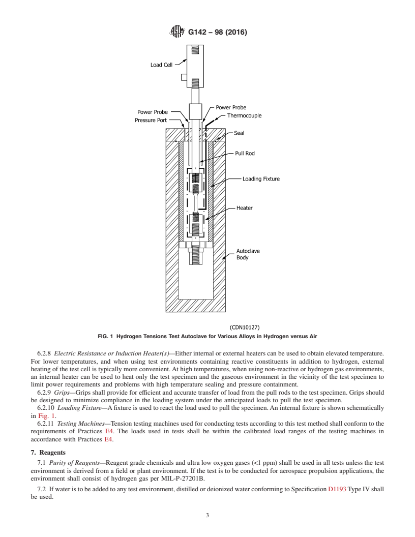
FIG. 1 Hydrogen Tensions Test Autoclave for Various Alloys in
opening and closing of the test cell and reliable sealing
Hydrogen versus Air
capabilities for hydrogen. This can include either metallic or
nonmetallic materials with high resistance to hydrogen em-
brittlement and degradation.
provide electrical isolation from the test cell and internal
6.2.3 Gas Port(s)—The gas port should be designed to
fixtures, and maintain a seal to prevent leakage of the test
promote flow and circulation of the gaseous test environments,
environment. If external heaters are used, no electric feed-
inert gas purging and evacuation as required to produce the
throughs would be required for testing.
intended test environment. Usually two ports are used so that
6.2.5 Tensile Feed-Through(s)—To apply tensile loading to
flow-through capabilities are attained to facilitate these func-
the test specimen it is necessary to have feed-through(s) which
tions.
provide linear motion and transmission of loads from an
6.2.4 Electrical Feed-Throughs—If very high temperature
external source. Care must be taken to design such feed-
conditions are required it may be advantageous to utilize an
throughs to have low friction to minimize errors due to friction
internal heater to heat the test specimen and the gaseous
losses when using externally applied loads. These are usually
environment in the immediate vicinity of the specimen.
designed to incorporate thermoplastic or elastomeric materials,
Therefore, a feed-through would be needed to reach an internal
or both. If elevated temperature tests are being conducted, then
resistance or induction heater. These feed-throughs must also
extreme care must be used in the selection of these materials to
alsoresistdeteriorationandlossofmechanicalpropertiesatthe
test temperature.
Kane, R. D., “High Temperature and High Pressure,” Corrosion Tests and
6.2.6 Pull Rod—The pull rod works in combination with the
Standards, Baboian, Robert, editor, ASTM, West Conshohocken, PA.
tensile feed-through to provide for loading of the test speci-
Metals Handbook, Vol 9, Corrosion, 9th Edition, ASM International, Metals
Park, OH, 1987, p. 1104. men. It is usually attached to a tensile testing machine on one
G142 − 98 (2016)
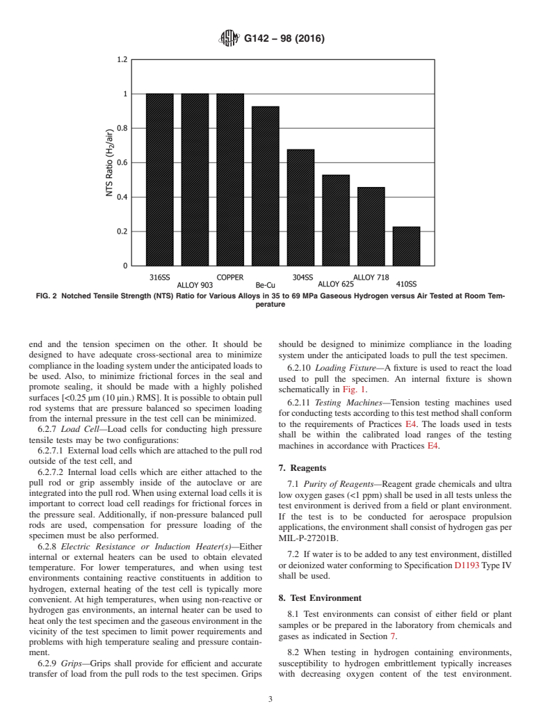
FIG. 2 Notched Tensile Strength (NTS) Ratio for Various Alloys in 35 to 69 MPa Gaseous Hydrogen versus Air Tested at Room Tem-
perature
end and the tension specimen on the other. It should be should be designed to minimize compliance in the loading
designed to have adequate cross-sectional area to minimize system under the anticipated loads to pull the test specimen.
complianceintheloadingsystemundertheanticipatedloadsto
6.2.10 Loading Fixture—A fixture is used to react the load
be used. Also, to minimize frictional forces in the seal and
used to pull the specimen. An internal fixture is shown
promote sealing, it should be made with a highly polished
schematically in Fig. 1.
surfaces [<0.25 µm (10 µin.) RMS]. It is possible to obtain pull
6.2.11 Testing Machines—Tension testing machines used
rod systems that are pressure balanced so specimen loading
forconductingtestsaccordingtothistestmethodshallconform
from the internal pressure in the test cell can be minimized.
to the requirements of Practices E4. The loads used in tests
6.2.7 Load Cell—Load cells for conducting high pressure
shall be within the calibrated load ranges of the testing
tensile tests may be two configurations:
machines in accordance with Practices E4.
6.2.7.1 External load cells which are attached to the pull rod
outside of the test cell, and
7. Reagents
6.2.7.2 Internal load cells which are either attached to the
pull rod or grip assembly inside of the autoclave or are
7.1 Purity of Reagents—Reagent grade chemicals and ultra
integrated into the pull rod.When using external load cells it is
low oxygen gases (<1 ppm) shall be used in all tests unless the
important to correct load cell readings for frictional forces in
test environment is derived from a field or plant environment.
the pressure seal. Additionally, if non-pressure balanced pull
If the test is to be conducted for aerospace propulsion
rods are used, compensation for pressure loading of the
applications, the environment shall consist of hydrogen gas per
specimen must be also performed.
MIL-P-27201B.
6.2.8 Electric Resistance or Induction Heater(s)—Either
7.2 If water is to be added to any test environment, distilled
internal or external heaters can be used to obtain elevated
ordeionizedwaterconformingtoSpecificationD1193TypeIV
temperature. For lower temperatures, and when using test
shall be used.
environments containing reactive constituents in addition to
hydrogen, external heating of the test cell is typically more
8. Test Environment
convenient. At high temperatures, when using non-reactive or
hydrogen gas environments, an internal heater can be used to
8.1 Test environments can consist of either field or plant
heat only the test specimen and the gaseous environment in the
samples or be prepared in the laboratory from chemicals and
vicinity of the test specimen to limit power requirements and
gases as indicated in Section 7.
problems with high temperature sealing and pressure contain-
ment. 8.2 When testing in hydrogen containing environments,
susceptibility to hydrogen embrittlement typically increases
6.2.9 Grips—Grips shall provide for efficient and accurate
transfer of load from the pull rods to the test specimen. Grips with decreasing oxygen content of the test environment.
G142 − 98 (2016)
Therefore, strict procedures for deaeration shall be followed
and periodically qualified for oxygen content as discussed in
Sections 9 and 11.
8.3 For purposes of standardization, suggested standardized
pressuresforhydrogengastestingshallbe7MPa,35MPa,and
69 MPa. However, for materials evaluation for specific
applications,thetestpressureshouldbeequaltoorgreaterthan
that which represents the service conditions.
9. Sampling
9.1 The procedure for sampling mill products is typically
covered in product or other specifications and is outside the
scope of this document.
9.2 Sampling of the test environment is recommended to
confirm that the test environment is in conformance with this
test method and attains the intended test conditions. Such
sampling shall be conducted immediately prior to and after
testing. The frequency of environmental sampling shall be as
required to cover applicable product, purchase or in-house
testingspecifications,orboth.Asaminimumrequirementtobe
in compliance with this test method, however, sampling of the
test environment shall be conducted at the start of testing and
againwhenanyelementofthetestprocedureortestsystemhas
been changed or modified.
10. Test Specimens
10.1 Tension specimens shall be used for evaluation of
FIG. 3 Standard Tension Specimens (a) Smooth and (b) Notched
hydrogen embrittlement.These specimens shall conform to the
dimensions and guidelines provided in Test Methods E8.
However, in some cases, the material size, configuration, and
form or the confines of various test cells may limit the actual
11.2.1 Low Resistance—Low Alloy Steel: UNS G43400
dimensions of the test specimen. In such cases, the specimen
(austenitize at 900°C for 1 h plus water quench and temper at
geometry and dimensions shall be fully described.Take care to
454°C for 2 h).
only compare the results obtained from similar specimens.
11.2.2 Intermediate Resistance—Nickel Base Alloy: UNS
N07718 (solution annealed at 954°C for 1 h plus air cool; age
10.2 For purposes of standardizing the evaluation of mate-
at 718°C for 8 h plus furnace cool to 620°C hold for 8 h plus
rials according to this test method, two standard test specimens
air cool).
shall be used: standard smooth tension specimen, and standard
11.2.3 High Resistance—Stainless Steels: A 286—AMS
notched tensile specimen. The dimensions of these specimens
5737(solutionannealedat893°Cfor1hpluswaterquenchand
are given in Fig. 3a and Fig. 3b.
aged at 721°C for 16 h plus air cool).
10.3 Specimens shall be machined to have a minimal
amount of cold work on the gage or notch surfaces.Total metal
12. Test Procedure
removedinthelasttwopassesshallbelimitedtoatotalof0.05
12.1 Follow the basic guidelines for high pressure/high
mmandhaveasurfacefinishof0.25µm(10µin
...
This document is not an ASTM standard and is intended only to provide the user of an ASTM standard an indication of what changes have been made to the previous version. Because
it may not be technically possible to adequately depict all changes accurately, ASTM recommends that users consult prior editions as appropriate. In all cases only the current version
of the standard as published by ASTM is to be considered the official document.
Designation: G142 − 98 (Reapproved 2011) G142 − 98 (Reapproved 2016)
Standard Test Method for
Determination of Susceptibility of Metals to Embrittlement in
Hydrogen Containing Environments at High Pressure, High
Temperature, or Both
This standard is issued under the fixed designation G142; the number immediately following the designation indicates the year of
original adoption or, in the case of revision, the year of last revision. A number in parentheses indicates the year of last reapproval. A
superscript epsilon (´) indicates an editorial change since the last revision or reapproval.
1. Scope
1.1 This test method covers a procedure for determination of tensile properties of metals in high pressure or high temperature,
or both, gaseous hydrogen-containing environments. It includes accommodations for the testing of either smooth or notched
specimens.
1.2 This test method applies to all materials and product forms including, but not restricted to, wrought and cast materials.
1.3 The values stated in SI units are to be regarded as standard. The values given in parentheses are for information only.
1.4 This standard does not purport to address all of the safety concerns, if any, associated with its use. It is the responsibility
of the user of this standard to establish appropriate safety and health practices and determine the applicability of regulatory
limitations prior to use.
2. Referenced Documents
2.1 ASTM Standards:
D1193 Specification for Reagent Water
E4 Practices for Force Verification of Testing Machines
E8 Test Methods for Tension Testing of Metallic Materials
E691 Practice for Conducting an Interlaboratory Study to Determine the Precision of a Test Method
G15 Terminology Relating to Corrosion and Corrosion Testing (Withdrawn 2010)
G111 Guide for Corrosion Tests in High Temperature or High Pressure Environment, or Both
G129 Practice for Slow Strain Rate Testing to Evaluate the Susceptibility of Metallic Materials to Environmentally Assisted
Cracking
2.2 Military Standard:
MIL-P-27201B Propellant, Hydrogen
3. Terminology
3.1 Definitions:
3.1.1 control test, n—a mechanical test conducted in an environment that does not produce embrittlement of a test material.
3.1.2 hydrogen embrittlement, n—hydrogen induced cracking or severe loss of ductility caused by the presence of hydrogen in
the metal.
3.1.3 Other definitions and terminology related to testing can be found in Terminology G15.
4. Summary of Test Method
4.1 Specimens of selected materials are exposed to a gaseous hydrogen containing environment at high pressure or high
temperature, or both, while being pulled to failure in uniaxial tension. The susceptibility to hydrogen embrittlement is evaluated
This test method is under the jurisdiction of ASTM Committee G01 on Corrosion of Metals and is the direct responsibility of Subcommittee G01.06 on Environmentally
Assisted Cracking.
Current edition approved March 1, 2011May 1, 2016. Published April 2011May 2016. Originally approved in 1996. Last previous edition approved in 20042011 as
G142–98(2004).G142 – 98 (2011). DOI: 10.1520/G0142-98R11.10.1520/G0142-98R16.
For referenced ASTM standards, visit the ASTM website, www.astm.org, or contact ASTM Customer Service at service@astm.org. For Annual Book of ASTM Standards
volume information, refer to the standard’s Document Summary page on the ASTM website.
The last approved version of this historical standard is referenced on www.astm.org.
Available from Standardization Documents Order Desk, DODSSP, Bldg. 4, Section D, 700 Robbins Ave., Philadelphia, PA 19111-5098
Copyright © ASTM International, 100 Barr Harbor Drive, PO Box C700, West Conshohocken, PA 19428-2959. United States
G142 − 98 (2016)
through the determination of standard mechanical properties in tension (that is, yield strength, ultimate tensile strength, notched
tensile strength, reduction in area or elongation, or both). Comparison of these mechanical properties determined in a
hydrogen-containing environment to those determined in a non-embrittling environment (control test) provides a general index of
susceptibility to cracking versus the material’s normal mechanical behavior.
5. Significance and Use
5.1 This test method provides a reliable prediction of the resistance or susceptibility, or both, to loss of material strength and
ductility as a result of exposure to hydrogen-containing gaseous environments. This test method is applicable over a broad range
of pressures, temperatures, and gaseous environments. The results from this test method can be used to evaluate the effects of
material composition, processing, and heat treatment as well as the effects of changes in environment composition, temperature,
and pressure. These results may or may not correlate with service experience for particular applications. Furthermore, this test
method may not be suitable for the evaluation of high temperature hydrogen attack in steels unless suitable exposure time at the
test conditions has taken place prior to the initiation of tensile testing to allow for the development of internal blistering,
decarburization or cracking, or both.
6. Apparatus
6.1 Since this test method is intended to be conducted at high pressures and may also involve high temperatures, the apparatus
must be constructed to safely contain the test environment while being resistant to the embrittling effects of hydrogen. Secondly,
the test apparatus must be capable of allowing introduction of the test gas, removal of air from the test cell, and accurate
performance of the tension test on the test specimen. In cases where the tests are conducted at elevated temperatures, the apparatus
must provide for heating of the specimen and the test environment in direct contact with the specimen.
6.2 Fig. 1 shows a schematic representation of a typical test cell designed to conduct HP/HT gaseous hydrogen embrittlement
experiments. The typical components include:
6.2.1 Metal Test Cell—The test cell should be constructed from materials that have proven to have high resistance to hydrogen
embrittlement under the conditions. A list of potential materials of construction is shown in Fig. 2. Materials with high values of
tensile ratios (environment versus a control environment) should be used. Materials with low values of this parameter should be
avoided.
6.2.2 Closure and Seal—To facilitate operation of the test cell and tension testing, the closure should provide for rapid opening
and closing of the test cell and reliable sealing capabilities for hydrogen. This can include either metallic or nonmetallic materials
with high resistance to hydrogen embrittlement and degradation.
6.2.3 Gas Port(s)—The gas port should be designed to promote flow and circulation of the gaseous test environments, inert gas
purging and evacuation as required to produce the intended test environment. Usually two ports are used so that flow-through
capabilities are attained to facilitate these functions.
6.2.4 Electrical Feed-Throughs—If very high temperature conditions are required it may be advantageous to utilize an internal
heater to heat the test specimen and the gaseous environment in the immediate vicinity of the specimen. Therefore, a feed-through
would be needed to reach an internal resistance or induction heater. These feed-throughs must also provide electrical isolation from
the test cell and internal fixtures, and maintain a seal to prevent leakage of the test environment. If external heaters are used, no
electric feed-throughs would be required for testing.
6.2.5 Tensile Feed-Through(s)—To apply tensile loading to the test specimen it is necessary to have feed-through(s) which
provide linear motion and transmission of loads from an external source. Care must be taken to design such feed-throughs to have
low friction to minimize errors due to friction losses when using externally applied loads. These are usually designed to incorporate
thermoplastic or elastomeric materials, or both. If elevated temperature tests are being conducted, then extreme care must be used
in the selection of these materials to also resist deterioration and loss of mechanical properties at the test temperature.
6.2.6 Pull Rod—The pull rod works in combination with the tensile feed-through to provide for loading of the test specimen.
It is usually attached to a tensile testing machine on one end and the tension specimen on the other. It should be designed to have
adequate cross-sectional area to minimize compliance in the loading system under the anticipated loads to be used. Also, to
minimize frictional forces in the seal and promote sealing, it should be made with a highly polished surfaces [<0.25 μm (10 μin.)
RMS]. It is possible to obtain pull rod systems that are pressure balanced so specimen loading from the internal pressure in the
test cell can be minimized.
6.2.7 Load Cell—Load cells for conducting high pressure tensile tests may be two configurations:
6.2.7.1 External load cells which are attached to the pull rod outside of the test cell, and
6.2.7.2 Internal load cells which are either attached to the pull rod or grip assembly inside of the autoclave or are integrated into
the pull rod. When using external load cells it is important to correct load cell readings for frictional forces in the pressure seal.
Additionally, if non-pressure balanced pull rods are used, compensation for pressure loading of the specimen must be also
performed.
Kane, R. D., “High Temperature and High Pressure,” Corrosion Tests and Standards, Baboian, Robert, editor, ASTM, West Conshohocken, PA.
Metals Handbook, Vol 9, Corrosion, 9th Edition, ASM International, Metals Park, OH, 1987, p. 1104.
G142 − 98 (2016)
FIG. 1 Hydrogen Tensions Test Autoclave for Various Alloys in Hydrogen versus Air
6.2.8 Electric Resistance or Induction Heater(s)—Either internal or external heaters can be used to obtain elevated temperature.
For lower temperatures, and when using test environments containing reactive constituents in addition to hydrogen, external
heating of the test cell is typically more convenient. At high temperatures, when using non-reactive or hydrogen gas environments,
an internal heater can be used to heat only the test specimen and the gaseous environment in the vicinity of the test specimen to
limit power requirements and problems with high temperature sealing and pressure containment.
6.2.9 Grips—Grips shall provide for efficient and accurate transfer of load from the pull rods to the test specimen. Grips should
be designed to minimize compliance in the loading system under the anticipated loads to pull the test specimen.
6.2.10 Loading Fixture—A fixture is used to react the load used to pull the specimen. An internal fixture is shown schematically
in Fig. 1.
6.2.11 Testing Machines—Tension testing machines used for conducting tests according to this test method shall conform to the
requirements of Practices E4. The loads used in tests shall be within the calibrated load ranges of the testing machines in
accordance with Practices E4.
7. Reagents
7.1 Purity of Reagents—Reagent grade chemicals and ultra low oxygen gases (<1 ppm) shall be used in all tests unless the test
environment is derived from a field or plant environment. If the test is to be conducted for aerospace propulsion applications, the
environment shall consist of hydrogen gas per MIL-P-27201B.
7.2 If water is to be added to any test environment, distilled or deionized water conforming to Specification D1193 Type IV shall
be used.
G142 − 98 (2016)
FIG. 2 Notched Tensile Strength (NTS) Ratio for Various Alloys in 35 to 69 MPa Gaseous Hydrogen versus Air Tested at Room Tem-
perature
8. Test Environment
8.1 Test environments can consist of either field or plant samples or be prepared in the laboratory from chemicals and gases as
indicated in Section 7.
8.2 When testing in hydrogen containing environments, susceptibility to hydrogen embrittlement typically increases with
decreasing oxygen content of the test environment. Therefore, strict procedures for deaeration shall be followed and periodically
qualified for oxygen content as discussed in Sections 9 and 11.
8.3 For purposes of standardization, suggested standardized pressures for hydrogen gas testing shall be 7 MPa, 35 MPa, and
69 MPa. However, for materials evaluation for specific applications, the test pressure should be equal to or greater than that which
represents the service conditions.
9. Sampling
9.1 The procedure for sampling mill products is typically covered in product or other specifications and is outside the scope of
this document.
9.2 Sampling of the test environment is recommended to confirm that the test environment is in conformance with this test
method and attains the intended test conditions. Such sampling shall be conducted immediately prior to and after testing. The
frequency of environmental sampling shall be as required to cover applicable product, purchase or in-house testing specifications,
or both. As a minimum requirement to be in compliance with this test method, however, sampling of the test environment shall
be conducted at the start of testing and again when any element of the test procedure or test system has been changed or modified.
10. Test Specimens
10.1 Tension specimens shall be used for evaluation of hydrogen embrittlement. These specimens shall conform to the
dimensions and guidelines provided in Test Methods E8. However, in some cases, the material size, configuration, and form or the
confines of various test cells may limit the actual dimensions of the test specimen. In such cases, the specimen geometry and
dimensions shall be fully described. Take care to only compare the results obtained from similar specimens.
10.2 For purposes of standardizing the evaluation of materials according to this test method, two standard test specimens shall
be used: standard smooth tension specimen, and standard notched tensile specimen. The dimensions of these specimens are given
in Fig. 3a and Fig. 3b.
10.3 Specimens shall be machined to have a minimal amount of cold work on the gage or notch surfaces. Total metal removed
in the last two passes shall be limited to a total of 0.05 mm and have a surface finish of 0.25 μm (10 μin.) or better. The method
of final machining of the gage section should be by grinding (not turning) to avoid localized grooves and cold work
...
Questions, Comments and Discussion
Ask us and Technical Secretary will try to provide an answer. You can facilitate discussion about the standard in here.