


ASTM E881-92(2015)
(Practice)Standard Practice for Exposure of Solar Collector Cover Materials to Natural Weathering Under Conditions Simulating Stagnation Mode
Standard Practice for Exposure of Solar Collector Cover Materials to Natural Weathering Under Conditions Simulating Stagnation Mode
SIGNIFICANCE AND USE
4.1 This practice describes a weathering box test fixture and establishes limits for the heat loss coefficients. Uniform exposure guidelines are provided to minimize the variables encountered during outdoor exposure testing.
4.2 Since the combination of elevated temperature and solar radiation may cause some solar collector cover materials to degrade more rapidly than either exposure alone, a weathering box that elevates the temperature of the cover materials is used.
4.3 This practice may be used to assist in the evaluation of solar collector cover materials in the stagnation mode. No single temperature or procedure can duplicate the range of temperatures and environmental conditions to which cover materials may be exposed during stagnation conditions. To assist in evaluation of solar collector cover materials in the operational mode, Practice E782 should be used. Insufficient data exist to obtain exact correlation between the behavior of materials exposed in accordance with this practice and actual in-service performance.
4.4 This practice may also be useful in comparing the performance of different materials at one site or the performance of the same material at different sites, or both.
4.5 Means of evaluating the effects of weathering are provided in Practice E765, and in other ASTM test methods that evaluate material properties.
4.6 Exposures of the type described in this practice may be used to evaluate the stability of solar collector cover materials when exposed outdoors to the varied influences that comprise weather. Exposure conditions are complex and changeable. Important factors are material temperature, climate, time of year, presence of industrial pollution, etc. Generally, because it is difficult to define or measure precisely the factors influencing degradation due to weathering, results of outdoor exposure tests must be taken as indicative only. Repeated exposure testing at different seasons over a period of more than one year is req...
SCOPE
1.1 This practice covers a procedure for the exposure of solar collector cover materials to the natural weather environment at elevated temperatures that approximate stagnation conditions in solar collectors having a combined back and edge loss coefficient of less than 1.5 W/(m2 · °C).
1.2 This practice is suitable for exposure of both glass and plastic solar collector cover materials. Provisions are made for exposure of single and double cover assemblies to accommodate the need for exposure of both inner and outer solar collector cover materials.
1.3 This practice does not apply to cover materials for evacuated collectors, photovoltaic cells, flat-plate collectors having a combined back and edge loss coefficient greater than 1.5 W/(m2 ·° C), or flat-plate collectors whose design incorporates means for limiting temperatures during stagnation.
1.4 This standard does not purport to address all of the safety concerns, if any, associated with its use. It is the responsibility of the user of this standard to establish appropriate safety and health practices and determine the applicability of regulatory limitations prior to use.
General Information
Buy Standard
Standards Content (Sample)
NOTICE: This standard has either been superseded and replaced by a new version or withdrawn.
Contact ASTM International (www.astm.org) for the latest information
Designation: E881 − 92 (Reapproved 2015)
Standard Practice for
Exposure of Solar Collector Cover Materials to Natural
Weathering Under Conditions Simulating Stagnation Mode
This standard is issued under the fixed designation E881; the number immediately following the designation indicates the year of
original adoption or, in the case of revision, the year of last revision.Anumber in parentheses indicates the year of last reapproval.A
superscript epsilon (´) indicates an editorial change since the last revision or reapproval.
1. Scope E765Practice for Evaluation of Cover Materials for Flat
Plate Solar Collectors (Withdrawn 1991)
1.1 This practice covers a procedure for the exposure of
E772Terminology of Solar Energy Conversion
solar collector cover materials to the natural weather environ-
E782Practice for Exposure of Cover Materials for Solar
ment at elevated temperatures that approximate stagnation
CollectorstoNaturalWeatheringUnderConditionsSimu-
conditionsinsolarcollectorshavingacombinedbackandedge
2 lating Operational Mode
loss coefficient of less than 1.5 W/(m ·°C).
G7Practice for Natural Weathering of Materials
1.2 This practice is suitable for exposure of both glass and 4
2.2 Other Documents:
plastic solar collector cover materials. Provisions are made for
Federal Specification HH-I-558B,Amendment 3, Insulation
exposure of single and double cover assemblies to accommo-
Blocks,Boards,Felts,Sleeving(PipeandTubeCovering),
date the need for exposure of both inner and outer solar
and Pipe Fitting CoveringThermal (Mineral Fiber, Indus-
collector cover materials.
trial Type) August 1976
1.3 This practice does not apply to cover materials for
3. Terminology
evacuated collectors, photovoltaic cells, flat-plate collectors
having a combined back and edge loss coefficient greater than
3.1 Definitions:
1.5 W/(m ·°C), or flat-plate collectors whose design incorpo-
3.1.1 For definitions of terms used in this practice, refer to
rates means for limiting temperatures during stagnation.
Terminology E772.
1.4 This standard does not purport to address all of the
4. Significance and Use
safety concerns, if any, associated with its use. It is the
responsibility of the user of this standard to establish appro- 4.1 Thispracticedescribesaweatheringboxtestfixtureand
priate safety, health, and environmental practices and deter- establishes limits for the heat loss coefficients. Uniform expo-
mine the applicability of regulatory limitations prior to use. sureguidelinesareprovidedtominimizethevariablesencoun-
1.5 This international standard was developed in accor- tered during outdoor exposure testing.
dance with internationally recognized principles on standard-
4.2 Sincethecombinationofelevatedtemperatureandsolar
ization established in the Decision on Principles for the
radiation may cause some solar collector cover materials to
Development of International Standards, Guides and Recom-
degrade more rapidly than either exposure alone, a weathering
mendations issued by the World Trade Organization Technical
boxthatelevatesthetemperatureofthecovermaterialsisused.
Barriers to Trade (TBT) Committee.
4.3 This practice may be used to assist in the evaluation of
solar collector cover materials in the stagnation mode. No
2. Referenced Documents
single temperature or procedure can duplicate the range of
2.1 ASTM Standards:
temperatures and environmental conditions to which cover
D1435Practice for Outdoor Weathering of Plastics
materials may be exposed during stagnation conditions. To
assist in evaluation of solar collector cover materials in the
operational mode, Practice E782 should be used. Insufficient
This practice is under the jurisdiction of ASTM Committee E44 on Solar,
data exist to obtain exact correlation between the behavior of
GeothermalandOtherAlternativeEnergySourcesandisthedirectresponsibilityof
materials exposed in accordance with this practice and actual
Subcommittee E44.20 on Optical Materials for Solar Applications.
in-service performance.
Current edition approved March 1, 2015. Published April 2015. Originally
approved in 1982. Last previous edition approved in 2009 as E881–92 (2009).
DOI: 10.1520/E0881-92R15.
2 3
For referenced ASTM standards, visit the ASTM website, www.astm.org, or The last approved version of this historical standard is referenced on
contact ASTM Customer Service at service@astm.org. For Annual Book of ASTM www.astm.org.
Standards volume information, refer to the standard’s Document Summary page on Federal Specification HH-I-558B has several classes of insulation material
the ASTM website. intended for high-temperature use.
Copyright © ASTM International, 100 Barr Harbor Drive, PO Box C700, West Conshohocken, PA 19428-2959. United States
E881 − 92 (2015)
4.4 This practice may also be useful in comparing the 5.1.2 Boxes that meet the requirements of 5.1.1 are de-
performance of different materials at one site or the perfor- scribed in Table 1. Fig. 1 and Fig. 2 illustrate the weathering
mance of the same material at different sites, or both. box test fixtures. Although Fig. 1 shows a square box, any
shape is permitted if the requirements in 5.1.1 are met.
4.5 Means of evaluating the effects of weathering are
Appendix X1 of this practice describes the method for deter-
provided in Practice E765, and in other ASTM test methods
mining the combined back and edge loss coefficient.
that evaluate material properties.
5.2 Contents of the Weathering Box Test Fixture: (1) a box,
4.6 Exposures of the type described in this practice may be
(2) insulation, (3) absorber, (4) box top, (5) spacer, (6) glazing
used to evaluate the stability of solar collector cover materials
frame, and (7) adhesive tapes.
when exposed outdoors to the varied influences that comprise
5.2.1 Theboxmayhaveanydimensionsandbemadeofany
weather. Exposure conditions are complex and changeable.
material as long as the requirements in 5.1.1 are met. A weep
Important factors are material temperature, climate, time of
hole shall be drilled at the lower end of the bottom of the box
year,presenceofindustrialpollution,etc.Generally,becauseit
to provide drainage and to minimize moisture accumulation.
isdifficulttodefineormeasurepreciselythefactorsinfluencing
degradation due to weathering, results of outdoor exposure
NOTE 2—It is desirable that the box and box top be made of a material
tests must be taken as indicative only. Repeated exposure
that will be unaffected by the exposure environment.Ametal resistant to
testingatdifferentseasonsoveraperiodofmorethanoneyear
corrosion encountered in the environment would be suitable. If wood is
used, it should be painted or treated on the exterior to make it resistant to
is required to confirm exposure tests at any one location.
moisture. In certain climates only rot-resistant wood should be used to
Control samples must always be used in weathering tests for
minimize deterioration during exposure.
comparative analysis.
5.2.2 The insulation shall be a material suitable for use at a
5. Weathering Box Test Fixture high temperature (for example, 150°C (302°F)).
5.1 Test Fixture Requirements:
NOTE 3—Insulation materials having resins or binders should not be
5.1.1 The weathering box test fixture shall be constructed
used because elevated temperatures may cause the resin or binder to
deteriorate and outgas. Outgassing products condense on the cover
such that the combined back and edge loss coefficient is less
2 2
material causing changes in the solar transmittance of the solar collector
than 1.5 W/(m ·°C) (0.264 Btu/(ft ·h·°F)) (Note 1). (The
cover material.
methodfordeterminingthiscoefficientisoutlinedinAppendix
X1ofthispractice.)Thedistancebetweentheabsorberandthe 5.2.3 The absorber shall be of an adequate size to cover the
interior surface of the weathering box aperture. The absorber
closestcoverplateshallbebetween13and38mm(0.5and1.5
shall have a flat black nonselective coating having an absorp-
in.). For a double-cover exposure the separation between the
tance not less than 0.90 after exposure.
inner and outer cover shall be between 13 and 38 mm (0.5 and
1.5in.).Notmorethan10%oftheabsorberplateareashallbe
5.2.4 Theboxtopshallbeofanadequatesizetofitoverthe
shadedwhenthesunisata30°anglewiththeplaneofthefront box.
surface of the exposure box.
NOTE 4—The box top is intended to protect the edges of the test
NOTE 1—A good flat-plate solar collector has a combined back and specimen in contact with the box from reaching excessively high
edge loss coefficient of less than about 1.5 W/(m ·°C) (0.264 Btu/ temperatures, to minimize exposure of the adhesive tape to sunlight, and
(ft ·h·°F). to minimize moisture penetration into the exposure test fixture.
TABLE 1 Examples of Weathering Box Test Fixtures with Combined Heat Loss Coefficient for Back and Edge Losses Less than
2 2
1.5 W/(m ·°C) (0.264 Btu/(ft ·h·°F))
Example 1 Example 2
Box material steel aluminum
Insulation material glass fiber glass fiber
l, length of aperture inside edge insulation 0.25 m (9.8 in.) 0.61 m (24 in.)
w, width of aperture inside edge insulation 0.13 m (5.2 in.) 0.61 m (24 in.)
h, distance from top of absorber to bottom of cover 0.013 m (0.5 in.) 0.038 m (1.5 in.)
plate
2 2 2 2
A , area of aperture of test fixture A =(l × w) 0.033 m (51 in. ) 0.372 m (576 in. )
a a
2 2 2 2
A , area of back insulation A =(l × w) 0.033 m (51 in. ) 0.372 m (576 in. )
b b
2 2 2 2
A , area of edge insulation A =2(l + w)h 0.01 m (15 in. ) 0.093 m (144 in. )
e e
d , thickness of back insulation 0.077 m (3 in.) 0.05 m (2 in.)
b
d , thickness of box 0.001 m (0.04 in.) 0.002 m (0.08 in.)
c
d , thickness of edge insulation 0.013 m (0.5 in.) 0.025 m (1 in.)
e
2 2
K , conductivity of back insulation 0.038 W/(m·°C) (0.22 Btu/(ft ·h·°F)) 0.038 W/(m·°C) (0.022 Btu/(ft ·h·°F))
b
2 2
K , conductivity of box 43 W/(m·°C) (24.9 Btu/(ft ·h·°F) 204 W/(m·°C) (118 Btu/(ft ·h·°F))
c
2 2
K , conductivity of edge insulation 0.038 W/(m·°C) (0.022 Btu/(ft ·h·°F)) 0.038 W/(m·°C) (0.022 Btu/(ft ·h·°F))
e
A /A 11
b a
A /A 0.305 0.25
e a
2 2 2 2
d /K 2.03 m ·°C/W (11.4 (ft ·h·°F)/Btu) 1.32 m ·°C/W (7.5 (ft ·h·°F)/Btu)
b b
−5 2 −4 2 −6 2 −5 2
d /K 2.33 × 10 m ·°C/W (1.32 × 10 (ft ·h·°F)/Btu) 9.8 × 10 m ·°C/W (5.6 × 10 (ft ·h·°F)/Btu)
c c
2 2 2 2
d /K 0.342 m ·°C/W (1.94 (ft ·h·°F)/Btu) 0.658 m ·°C/W (3.74 (ft ·h·°F)/Btu)
e e
2 2 2 2
U , back + U , edge 1.38 W/(m ·°C) (0.243 Btu/(ft ·h·°F)) 1.14 W/(m ·°C) (0.201 Btu/(ft ·h·°F))
L L
E881 − 92 (2015)
FIG. 1 Top View of Weathering Box Test Fixture
FIG. 2 Assembled Weathering Box Test Fixture
5.2.5 The glazing frame is intended to hold the cover plate 5.2.6 The spacer shall provide a separation of 13 to 38 mm
material. The glazing frame shall have dimensions similar to (0.5to1.5in.)betweentheabsorberandtheclosestcoverplate.
the perimeter of the box. For a double-cover exposure the
Exact dimensions of the spacer are related to the requirements
frame shall provide a separation between the two cover plates
in 5.1.1.
ofnotlessthan13mm(0.5in.)orgreaterthan38mm(1.5in.).
NOTE 5—Certain designs of weathering boxes may eliminate the need
Exact dimensions of the frame are related to the requirements
for the spacer.
in 5.1.1. A vent hole may be drilled at one end of the glazing
frame to provide drainage and to minimize moisture accumu-
lation.
E881 − 92 (2015)
TABLE 2 Variable-Angle Rack Adjustment Schedule Using Four
5.2.7 The adhesive tapes shall be stable when exposed to
A,B
Changes Per Year
moisture and elevated temperatures. They shall be compatible
Calendar Period
with the specific materials from which the box, glazing frame,
Rack Tilt Angle, °
Dates Days of Year
box top, and cover plate are made.
Latitude ±2.5 3/2 to 4/11 61 to 101
5.2.8 Organic materials are potential sources of outgassing
Latitude − 16) ±2.5 4/12 to 8/31 102 to 243
andshallbeeliminatedfromtheinterioroftheweatheringbox
Latitude ±2.5 9/1 to 10/10 244 to 283
where possible. For example, metallic parts shall be cleaned to (Latitude + 16) ±2.5 10/11 to 3/1 284 to 60
A
remove traces of grease or other foreign matter. Other possible This exposure schedule may be used in both northern and southern hemi-
spheres.Thelatitudeinthesouthernhemisphereisnegative.Positiverackangles
sources of outgassing include coatings and sealants. Test
face south.
fixture components containing organic materials (for example, B
Theincidentangleofbeamradiation(θ)atsolarnoonforasouth-facingcollector
absorber coatings or insulation) shall be heated in an oven at is#8°.
150°C (302°F) for 24 h before the test fixture is assembled.
Thisshouldminimizeoutgassingthatresultsfromdeterioration
of the organic components exposed to elevated temperatures.
face south. Choose the angles so that the weathering boxes are
5.3 Test Specimen:
never closer to the horizontal than by 5°. Other variable
5.3.1 Thetestspecimenshallbeofanadequatesizetocover
exposure schedules requiring more than four adjustments per
the aperture of the box or glazing frame and to permit suitable
year may be used. The method for determining the variable
attachment.
angle exposure schedule is described in Appendix X2 of this
practice.
NOTE 6—Adequate allowances should be made for materials that will
undergo dimensional changes due to temperature.
6.3 When a number of weathering boxes are exposed
5.3.2 The test specimen identification marks shall not inter-
simultaneously,mounttheboxessidebysidewiththesidesnot
fere with either the exposure or the subsequent testing.
touching.
5.4 Sample Mounting:
6.4 Do not clean the solar collector cover materials during
5.4.1 Rigid and Semirigid Glazings:
exposure.
5.4.1.1 Lay the test specimen for single cover exposure
6.5 Visually inspect the test specimens at intervals of not
directly on either the spacer or the glazing frames. If used, the
more than one month. Record all changes in appearance.
frame is then placed on the spacer in the weathering box (see
Fig. 2).
7. Report
5.4.1.2 Lay the test specimen for inner cover exposure of a
7.1 The report shall include the following:
double cover assembly on the spacer or attach it to the glazing
7.1.1 Description of the weathering box test fixture and its
framebeforetheglazingframeisplacedinthebox(seeFig.2).
calculated combined back and edge loss coefficient,
5.4.1.3 Lay the test specimen for outer cover exposure of a
7.1.2 Whether the solar collector cover materials are ex-
doublecoverassemblyonthetopoftheglazingframe(seeFig.
posed as a single- or double-cover configuration and whether
2).
the test specimen was the inner or outer cover,
5.4.2 Films—Placefilmtestspecimensontheglazingframe
7.1.3 Complete identification of the solar collector outer
usingadhesivetransf
...
This document is not an ASTM standard and is intended only to provide the user of an ASTM standard an indication of what changes have been made to the previous version. Because
it may not be technically possible to adequately depict all changes accurately, ASTM recommends that users consult prior editions as appropriate. In all cases only the current version
of the standard as published by ASTM is to be considered the official document.
Designation: E881 − 92 (Reapproved 2009) E881 − 92 (Reapproved 2015)
Standard Practice for
Exposure of Solar Collector Cover Materials to Natural
Weathering Under Conditions Simulating Stagnation Mode
This standard is issued under the fixed designation E881; the number immediately following the designation indicates the year of
original adoption or, in the case of revision, the year of last revision. A number in parentheses indicates the year of last reapproval. A
superscript epsilon (´) indicates an editorial change since the last revision or reapproval.
1. Scope
1.1 This practice covers a procedure for the exposure of solar collector cover materials to the natural weather environment at
elevated temperatures that approximate stagnation conditions in solar collectors having a combined back and edge loss coefficient
of less than 1.5 W/(m · °C).
1.2 This practice is suitable for exposure of both glass and plastic solar collector cover materials. Provisions are made for
exposure of single and double cover assemblies to accommodate the need for exposure of both inner and outer solar collector cover
materials.
1.3 This practice does not apply to cover materials for evacuated collectors, photovoltaic cells, flat-plate collectors having a
combined back and edge loss coefficient greater than 1.5 W/(m ·° C), or flat-plate collectors whose design incorporates means for
limiting temperatures during stagnation.
1.4 This standard does not purport to address all of the safety concerns, if any, associated with its use. It is the responsibility
of the user of this standard to establish appropriate safety and health practices and determine the applicability of regulatory
limitations prior to use.
2. Referenced Documents
2.1 ASTM Standards:
D1435 Practice for Outdoor Weathering of Plastics
E765 Practice for Evaluation of Cover Materials for Flat Plate Solar Collectors (Withdrawn 1991)
E772 Terminology of Solar Energy Conversion
E782 Practice for Exposure of Cover Materials for Solar Collectors to Natural Weathering Under Conditions Simulating
Operational Mode
G7 Practice for Atmospheric Environmental Exposure Testing of Nonmetallic Materials
2.2 Other Documents:
Federal Specification HH-I-558B, Amendment 3, Insulation Blocks, Boards, Felts, Sleeving (Pipe and Tube Covering), and Pipe
Fitting Covering Thermal (Mineral Fiber, Industrial Type) August 1976
3. Terminology
3.1 Definitions:
3.1.1 For definitions of terms used in this practice, refer to Terminology E772.
4. Significance and Use
4.1 This practice describes a weathering box test fixture and establishes limits for the heat loss coefficients. Uniform exposure
guidelines are provided to minimize the variables encountered during outdoor exposure testing.
This practice is under the jurisdiction of ASTM Committee E44 on Solar, Geothermal and Other Alternative Energy Sources and is the direct responsibility of
Subcommittee E44.05 on Solar Heating and Cooling Systems and Materials.
Current edition approved April 1, 2009March 1, 2015. Published June 2009April 2015. Originally approved in 1982. Last previous edition approved in 20032009 as
E881–92(2003).E881–92(2009). DOI: 10.1520/E0881-92R09.10.1520/E0881-92R15.
For referenced ASTM standards, visit the ASTM website, www.astm.org, or contact ASTM Customer Service at service@astm.org. For Annual Book of ASTM Standards
volume information, refer to the standard’s Document Summary page on the ASTM website.
The last approved version of this historical standard is referenced on www.astm.org.
Federal Specification HH-I-558B has several classes of insulation material intended for high-temperature use.
Copyright © ASTM International, 100 Barr Harbor Drive, PO Box C700, West Conshohocken, PA 19428-2959. United States
E881 − 92 (2015)
4.2 Since the combination of elevated temperature and solar radiation may cause some solar collector cover materials to degrade
more rapidly than either exposure alone, a weathering box that elevates the temperature of the cover materials is used.
4.3 This practice may be used to assist in the evaluation of solar collector cover materials in the stagnation mode. No single
temperature or procedure can duplicate the range of temperatures and environmental conditions to which cover materials may be
exposed during stagnation conditions. To assist in evaluation of solar collector cover materials in the operational mode, Practice
E782 should be used. Insufficient data exist to obtain exact correlation between the behavior of materials exposed in accordance
with this practice and actual in-service performance.
4.4 This practice may also be useful in comparing the performance of different materials at one site or the performance of the
same material at different sites, or both.
4.5 Means of evaluating the effects of weathering are provided in Practice E765, and in other ASTM test methods that evaluate
material properties.
4.6 Exposures of the type described in this practice may be used to evaluate the stability of solar collector cover materials when
exposed outdoors to the varied influences that comprise weather. Exposure conditions are complex and changeable. Important
factors are material temperature, climate, time of year, presence of industrial pollution, etc. Generally, because it is difficult to
define or measure precisely the factors influencing degradation due to weathering, results of outdoor exposure tests must be taken
as indicative only. Repeated exposure testing at different seasons over a period of more than one year is required to confirm
exposure tests at any one location. Control samples must always be used in weathering tests for comparative analysis.
5. Weathering Box Test Fixture
5.1 Test Fixture Requirements:
5.1.1 The weathering box test fixture shall be constructed such that the combined back and edge loss coefficient is less than 1.5
2 2
W/(m · °C) (0.264 Btu/(ft · h · °F)) (Note 1). (The method for determining this coefficient is outlined in Appendix X1 of this
practice.) The distance between the absorber and the closest cover plate shall be between 13 and 38 mm (0.5 and 1.5 in.). For a
double-cover exposure the separation between the inner and outer cover shall be between 13 and 38 mm (0.5 and 1.5 in.). Not more
than 10 % of the absorber plate area shall be shaded when the sun is at a 30° angle with the plane of the front surface of the
exposure box.
2 2
NOTE 1—A good flat-plate solar collector has a combined back and edge loss coefficient of less than about 1.5 W/(m · °C) (0.264 Btu/(ft · h·°F).
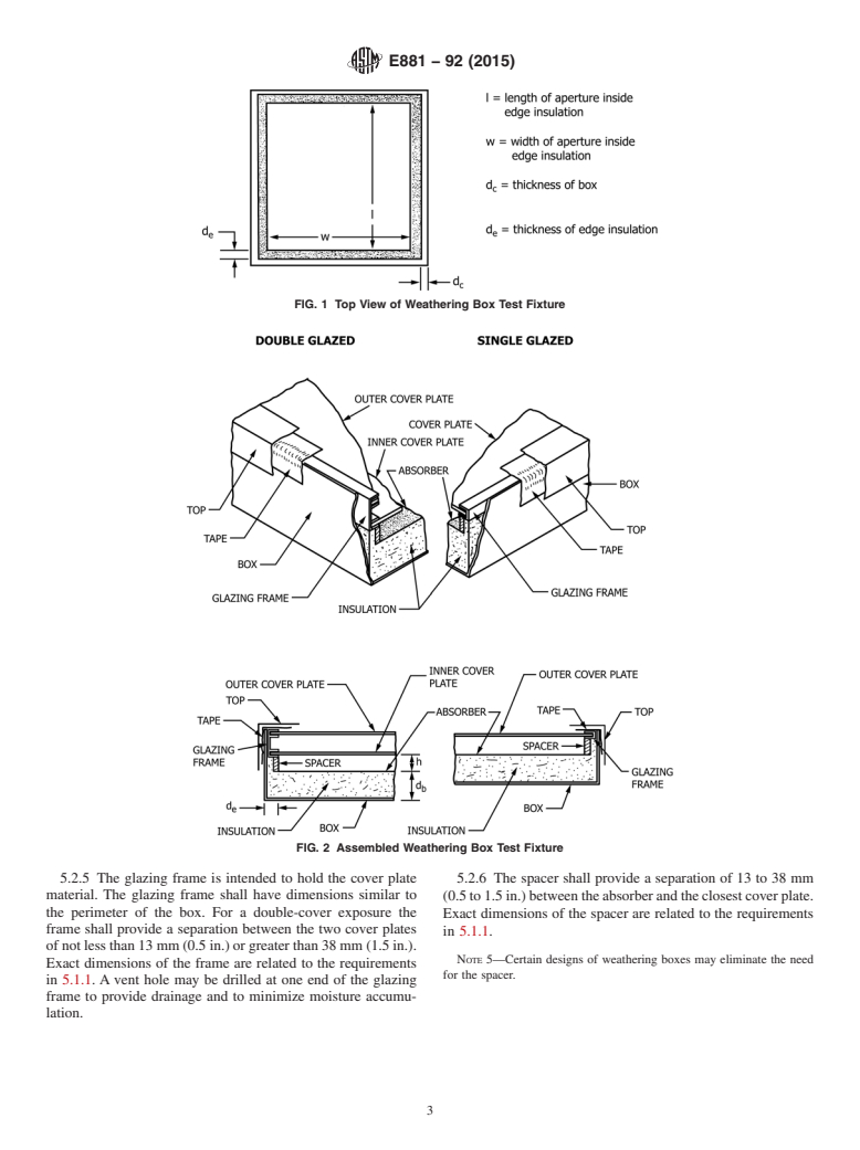
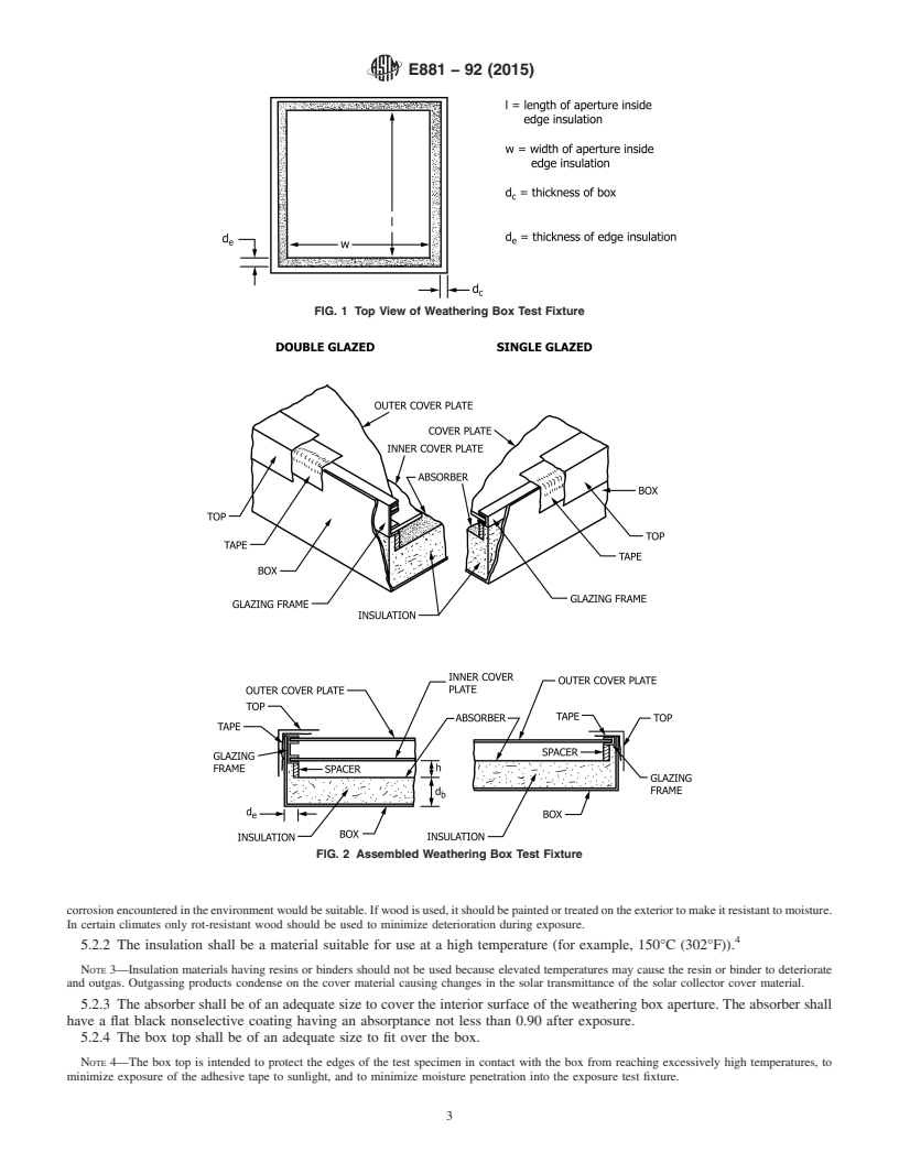
5.1.2 Boxes that meet the requirements of 5.1.1 are described in Table 1. Fig. 1 and Fig. 2 illustrate the weathering box test
fixtures. Although Fig. 1 shows a square box, any shape is permitted if the requirements in 5.1.1 are met. Appendix X1 of this
practice describes the method for determining the combined back and edge loss coefficient.
5.2 Contents of the Weathering Box Test Fixture: (1) a box, (2) insulation, (3) absorber, (4) box top, (5) spacer, (6) glazing frame,
and (7) adhesive tapes.
5.2.1 The box may have any dimensions and be made of any material as long as the requirements in 5.1.1 are met. A weep hole
shall be drilled at the lower end of the bottom of the box to provide drainage and to minimize moisture accumulation.
NOTE 2—It is desirable that the box and box top be made of a material that will be unaffected by the exposure environment. A metal resistant to
TABLE 1 Examples of Weathering Box Test Fixtures with Combined Heat Loss Coefficient for Back and Edge Losses Less than
2 2
1.5 W/(m ·°C) (0.264 Btu/(ft ·h·°F))
Example 1 Example 2
Box material steel aluminum
Insulation material glass fiber glass fiber
l, length of aperture inside edge insulation 0.25 m (9.8 in.) 0.61 m (24 in.)
w, width of aperture inside edge insulation 0.13 m (5.2 in.) 0.61 m (24 in.)
h, distance from top of absorber to bottom of cover 0.013 m (0.5 in.) 0.038 m (1.5 in.)
plate
2 2 2 2
A , area of aperture of test fixture A = (l × w) 0.033 m (51 in. ) 0.372 m (576 in. )
a a
2 2 2 2
A , area of back insulation A = (l × w) 0.033 m (51 in. ) 0.372 m (576 in. )
b b
2 2 2 2
A , area of edge insulation A = 2(l + w) h 0.01 m (15 in. ) 0.093 m (144 in. )
e e
d , thickness of back insulation 0.077 m (3 in.) 0.05 m (2 in.)
b
d , thickness of box 0.001 m (0.04 in.) 0.002 m (0.08 in.)
c
d , thickness of edge insulation 0.013 m (0.5 in.) 0.025 m (1 in.)
e
2 2
K , conductivity of back insulation 0.038 W/(m·°C) (0.22 Btu/(ft ·h·°F)) 0.038 W/(m·°C) (0.022 Btu/(ft ·h·°F))
b
2 2
K , conductivity of box 43 W/(m·°C) (24.9 Btu/(ft ·h·°F) 204 W/(m·°C) (118 Btu/(ft ·h·°F))
c
2 2
K , conductivity of edge insulation 0.038 W/(m·°C) (0.022 Btu/(ft ·h·°F)) 0.038 W/(m·°C) (0.022 Btu/(ft ·h·°F))
e
A /A 1 1
b a
A /A 0.305 0.25
e a
2 2 2 2
d /K 2.03 m ·°C/W (11.4 (ft ·h·°F)/Btu) 1.32 m ·°C/W (7.5 (ft ·h·°F)/Btu)
b b
− 5 2 −4 2 − 6 2 −5 2
d /K 2.33 × 10 m ·°C/W (1.32 × 10 (ft ·h·°F)/Btu) 9.8 × 10 m ·°C/W (5.6 × 10 (ft ·h·°F)/Btu)
c c
2 2 2 2
d /K 0.342 m ·°C/W (1.94 (ft ·h·°F)/Btu) 0.658 m ·°C/W (3.74 (ft ·h·°F)/Btu)
e e
2 2 2 2
U , back + U , edge 1.38 W/(m ·°C) (0.243 Btu/(ft ·h·°F)) 1.14 W/(m ·°C) (0.201 Btu/(ft ·h·°F))
L L
E881 − 92 (2015)
FIG. 1 Top View of Weathering Box Test Fixture
FIG. 2 Assembled Weathering Box Test Fixture
corrosion encountered in the environment would be suitable. If wood is used, it should be painted or treated on the exterior to make it resistant to moisture.
In certain climates only rot-resistant wood should be used to minimize deterioration during exposure.
5.2.2 The insulation shall be a material suitable for use at a high temperature (for example, 150°C (302°F)).
NOTE 3—Insulation materials having resins or binders should not be used because elevated temperatures may cause the resin or binder to deteriorate
and outgas. Outgassing products condense on the cover material causing changes in the solar transmittance of the solar collector cover material.
5.2.3 The absorber shall be of an adequate size to cover the interior surface of the weathering box aperture. The absorber shall
have a flat black nonselective coating having an absorptance not less than 0.90 after exposure.
5.2.4 The box top shall be of an adequate size to fit over the box.
NOTE 4—The box top is intended to protect the edges of the test specimen in contact with the box from reaching excessively high temperatures, to
minimize exposure of the adhesive tape to sunlight, and to minimize moisture penetration into the exposure test fixture.
E881 − 92 (2015)
5.2.5 The glazing frame is intended to hold the cover plate material. The glazing frame shall have dimensions similar to the
perimeter of the box. For a double-cover exposure the frame shall provide a separation between the two cover plates of not less
than 13 mm (0.5 in.) or greater than 38 mm (1.5 in.). Exact dimensions of the frame are related to the requirements in 5.1.1. A
vent hole may be drilled at one end of the glazing frame to provide drainage and to minimize moisture accumulation.
5.2.6 The spacer shall provide a separation of 13 to 38 mm (0.5 to 1.5 in.) between the absorber and the closest cover plate.
Exact dimensions of the spacer are related to the requirements in 5.1.1.
NOTE 5—Certain designs of weathering boxes may eliminate the need for the spacer.
5.2.7 The adhesive tapes shall be stable when exposed to moisture and elevated temperatures. They shall be compatible with
the specific materials from which the box, glazing frame, box top, and cover plate are made.
5.2.8 Organic materials are potential sources of outgassing and shall be eliminated from the interior of the weathering box where
possible. For example, metallic parts shall be cleaned to remove traces of grease or other foreign matter. Other possible sources
of outgassing include coatings and sealants. Test fixture components containing organic materials (for example, absorber coatings
or insulation) shall be heated in an oven at 150°C (302°F) for 24 h before the test fixture is assembled. This should minimize
outgassing that results from deterioration of the organic components exposed to elevated temperatures.
5.3 Test Specimen:
5.3.1 The test specimen shall be of an adequate size to cover the aperture of the box or glazing frame and to permit suitable
attachment.
NOTE 6—Adequate allowances should be made for materials that will undergo dimensional changes due to temperature.
5.3.2 The test specimen identification marks shall not interfere with either the exposure or the subsequent testing.
5.4 Sample Mounting:
5.4.1 Rigid and Semirigid Glazings:
5.4.1.1 Lay the test specimen for single cover exposure directly on either the spacer or the glazing frames. If used, the frame
is then placed on the spacer in the weathering box (see Fig. 2).
5.4.1.2 Lay the test specimen for inner cover exposure of a double cover assembly on the spacer or attach it to the glazing frame
before the glazing frame is placed in the box (see Fig. 2).
5.4.1.3 Lay the test specimen for outer cover exposure of a double cover assembly on the top of the glazing frame (see Fig. 2).
5.4.2 Films—Place film test specimens on the glazing frame using adhesive transfer tape to hold the test specimen taut. It is
essential that uniform tensioning be obtained prior to applying the tape. Then place the frame in the box similar to 5.4.1.1, 5.4.1.2,
and 5.4.1.3.
5.5 Assembly of Weathering Box:
5.5.1 Slide the various parts of the weathering box test fixture into position. The outer glazing must be roughly flush with the
top side of the box. The position of an inner glazing, if used, shall be nearest the bottom of the box.
5.5.2 After assembly, seal the frame and outer glazing in place with an adhesive tape to prevent moisture intrusion. Place the
box top on the box (see Fig. 2).
6. Natural Weathering Exposure
6.1 Mount the weathering boxes in a backed condition using 13-mm (0.5-in.) exterior grade plywood on weathering racks such
as those described in Practice D1435. The racks shall be capable of having the angles adjusted and have their axis of rotation on
an east-west line.
6.2 Use a variable angle exposure to maximize solar radiation incident upon the weathering box. Adjust the racks according to
the schedule given in Table 2. Positive rack angles face south. Choose the angles so that the weathering boxes are never closer
to the horizontal than by 5°. Other vari
...
Questions, Comments and Discussion
Ask us and Technical Secretary will try to provide an answer. You can facilitate discussion about the standard in here.