


ASTM D3633/D3633M-12(2019)
(Test Method)Standard Test Method for Electrical Resistivity of Membrane-Pavement Systems
Standard Test Method for Electrical Resistivity of Membrane-Pavement Systems
SIGNIFICANCE AND USE
4.1 This test method for measuring the electrical resistivity of water-barrier membrane-pavement systems may be interpreted to indicate the effectiveness of such systems.
4.2 This test method is predicated on the fact that an electrical connection between the surface of the pavement and the reinforcing steel in the concrete pavement cannot be made through an impermeable water-barrier membrane.
4.3 This test method may be used for acceptance when the accepting agency specifies the minimum resistance value desired.
SCOPE
1.1 This test method covers the measurement of the electrical resistivity of water-barrier membrane-pavement systems when applied to concrete bridge decks.
1.2 Measurements shall be performed on the bituminous pavement surface covering the water-barrier membrane.
1.3 This test method utilizes a measure of electrical resistance between the saturated top surface of the water-barrier membrane and the reinforcing steel embedded in the concrete bridge deck.
1.4 The values measured represent the electrical resistance obtained with the equipment and procedures stated herein and do not necessarily agree or correlate with those using other equipment or procedures.
1.5 Units—The values stated in either SI units or inch-pound units are to be regarded separately as standard. The values stated in each system may not be exact equivalents; therefore, each system shall be used independently of the other. Combining values from the two systems may result in nonconformance with the standard.
1.6 This standard does not purport to address all of the safety concerns, if any, associated with its use. It is the responsibility of the user of this standard to establish appropriate safety, health, and environmental practices and determine the applicability of regulatory limitations prior to use.
1.7 This international standard was developed in accordance with internationally recognized principles on standardization established in the Decision on Principles for the Development of International Standards, Guides and Recommendations issued by the World Trade Organization Technical Barriers to Trade (TBT) Committee.
General Information
Buy Standard
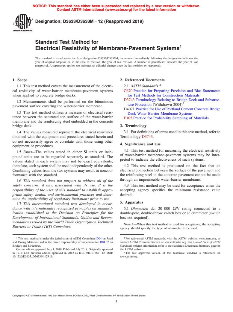
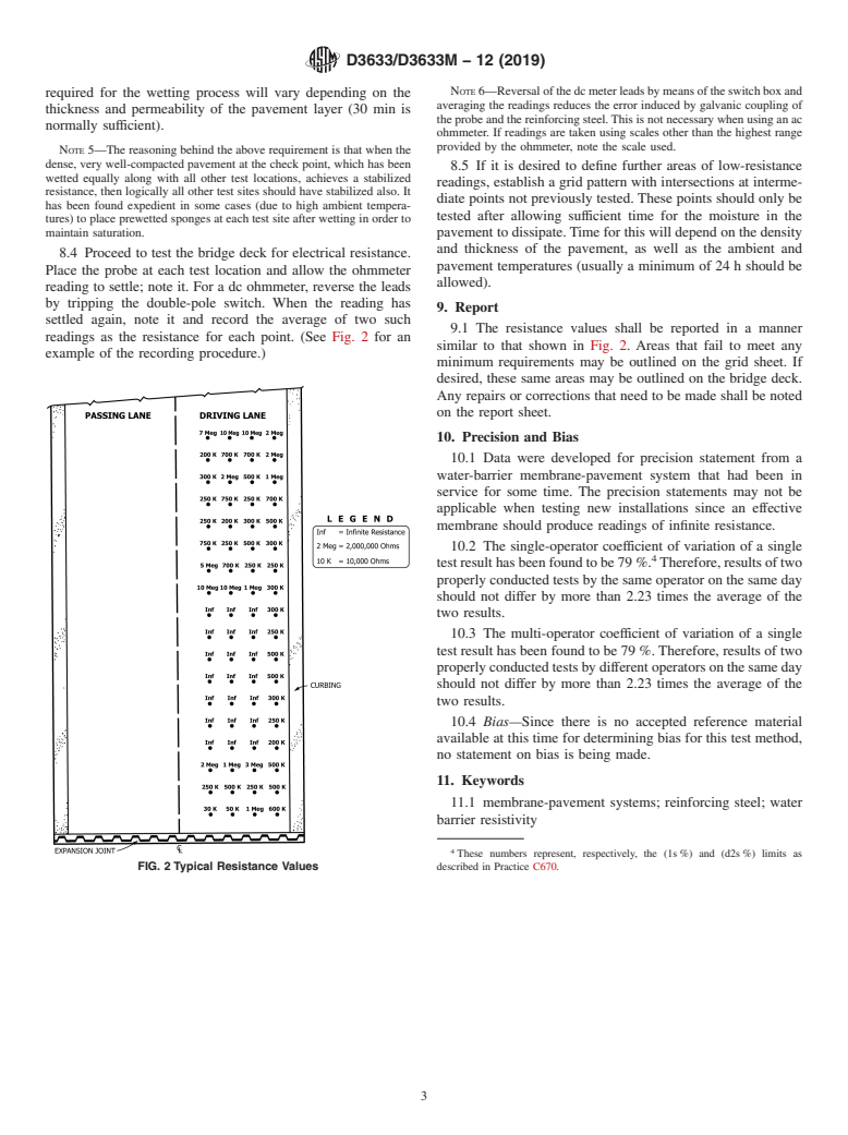
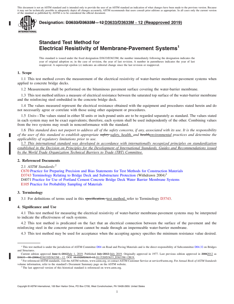
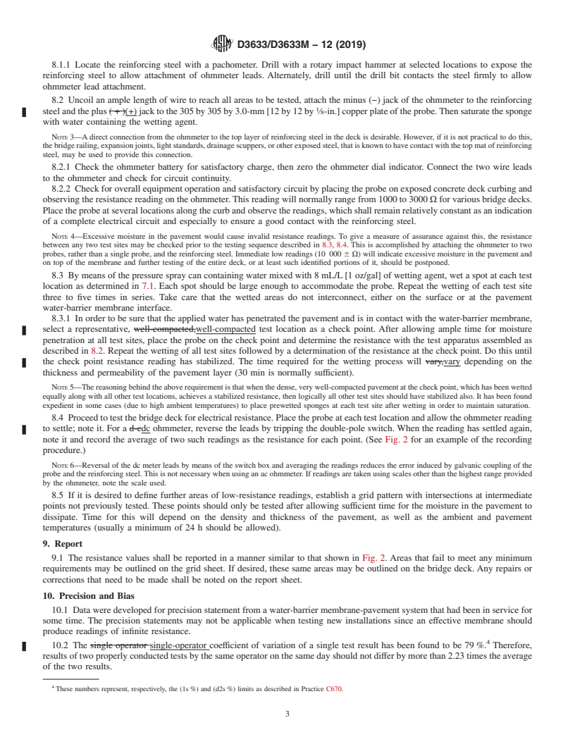
Standards Content (Sample)
NOTICE: This standard has either been superseded and replaced by a new version or withdrawn.
Contact ASTM International (www.astm.org) for the latest information
Designation: D3633/D3633M − 12 (Reapproved 2019)
Standard Test Method for
Electrical Resistivity of Membrane-Pavement Systems
This standard is issued under the fixed designation D3633/D3633M; the number immediately following the designation indicates the
year of original adoption or, in the case of revision, the year of last revision. A number in parentheses indicates the year of last
reapproval. A superscript epsilon (´) indicates an editorial change since the last revision or reapproval.
1. Scope 2. Referenced Documents
1.1 This test method covers the measurement of the electri- 2.1 ASTM Standards:
cal resistivity of water-barrier membrane-pavement systems C670 Practice for Preparing Precision and Bias Statements
when applied to concrete bridge decks. for Test Methods for Construction Materials
D3743 Terminology Relating to Bridge Deck and Substruc-
1.2 Measurements shall be performed on the bituminous
ture Protection (Withdrawn 2004)
pavement surface covering the water-barrier membrane.
D4071 Practice for Use of Portland Cement Concrete Bridge
1.3 This test method utilizes a measure of electrical resis-
Deck Water Barrier Membrane Systems
tance between the saturated top surface of the water-barrier
E105 Practice for Probability Sampling of Materials
membrane and the reinforcing steel embedded in the concrete
3. Terminology
bridge deck.
1.4 The values measured represent the electrical resistance 3.1 For definitions of terms used in this test method, refer to
Terminology D3743.
obtained with the equipment and procedures stated herein and
do not necessarily agree or correlate with those using other
4. Significance and Use
equipment or procedures.
4.1 This test method for measuring the electrical resistivity
1.5 Units—The values stated in either SI units or inch-
of water-barrier membrane-pavement systems may be inter-
pound units are to be regarded separately as standard. The
preted to indicate the effectiveness of such systems.
values stated in each system may not be exact equivalents;
4.2 This test method is predicated on the fact that an
therefore, each system shall be used independently of the other.
electrical connection between the surface of the pavement and
Combining values from the two systems may result in noncon-
formance with the standard. the reinforcing steel in the concrete pavement cannot be made
through an impermeable water-barrier membrane.
1.6 This standard does not purport to address all of the
safety concerns, if any, associated with its use. It is the
4.3 This test method may be used for acceptance when the
responsibility of the user of this standard to establish appro- accepting agency specifies the minimum resistance value
priate safety, health, and environmental practices and deter-
desired.
mine the applicability of regulatory limitations prior to use.
5. Apparatus
1.7 This international standard was developed in accor-
dance with internationally recognized principles on standard- 5.1 Ohmmeter, dc, 20 000 Ω/V rating connected to a
ization established in the Decision on Principles for the
double-pole, double-throw switch box or ac ohmmeter (switch
Development of International Standards, Guides and Recom- box not required).
mendations issued by the World Trade Organization Technical
NOTE 1—When this test method is used for acceptance, the accepting
Barriers to Trade (TBT) Committee.
agency should specify the type of ohmmeter to be used.
1 2
This test method is under the jurisdiction of ASTM Committee D04 on Road For referenced ASTM standards, visit the ASTM website, www.astm.org, or
and Paving Materials and is the direct responsibility of Subcommittee D04.32 on contact ASTM Customer Service at service@astm.org. For Annual Book of ASTM
Bridges and Structures. Standards volume information, refer to the standard’s Document Summary page on
Current edition approved July 1, 2019. Published July 2019. Originally approved the ASTM website.
in 1977. Last previous edition approved in 2012 as D3633/D3633M – 12. DOI: The last approved version of this historical standard is referenced on
10.1520/D3633_D3633M-12R19. www.astm.org.
Copyright © ASTM International, 100 Barr Harbor Drive, PO Box C700, West Conshohocken, PA 19428-2959. United States
D3633/D3633M − 12 (2019)
5.2 Insulated Wire, No. 18, Belden test probewire or equiva- similar method, that will ensure that the bridge deck area to be
lent. Two spools, minimum 38 m [125 ft]. tested will be adequately represented.
5.3 Copper Plate, 305 by 305 by 3.0 mm [12 by 12 by
8. Procedure
⁄8 in.], with the means for connecting the ohmmeter lead and
8.1 Prepare the surface to be tested by removing all foreign
a wooden handle approximately 1 m [39 in.] in length.
material by sweeping or scraping, or both. Do not use water to
5.4 Polyurethane Sponge, 305 by 305 by 13 mm [12 by 12
clean. The surface shall be dry and clean before testing.
by ⁄2 in.], to be attached to the copper plate with rubber bands
8.1.1 Locate the reinforcing steel with a pachometer. Drill
or other suitable means. When assembled, this apparatus is
with a rotary impact hammer at selected locations to expose the
called the probe.
reinforcing steel to allow attachment of ohmmeter leads.
5.5 Pressure Spray Can, 12-L [3-gal] capacity, with a hose
Alternately, drill until the drill bit contacts the steel firmly to
and spray nozzle.
allow ohmmeter lead attachment.
8.2 Uncoil an ample length of wire to reach all areas to be
6. Reagent
tested, attach the minus (−) jack of the ohmmeter to the
6.1 A wetting agent which, when added to the water, will
reinforcing steel and the plus (+) jack to the 305 by 305 by
break the surface tension and promote the penetration of the
3.0-mm [12 by 12 by ⁄8-in.] copper plate of the probe. Then
water through the bituminous pavement.
saturate the sponge with water containing the wetting agent.
NOTE 2—An example of a wetting agent is a super-saturated solution of
NOTE 3—A direct connection from the ohmmeter to the top layer of
cupric sulfate crystals in warm water to which is added 19 mL/gal of
reinforcing steel in the deck is desirable. However, if it is not practical to
dioctyl sodium sulfo-succinate (tradename “Aerosol” OT Clear, 10 %).
do this, the bridge railing, expansion joints, light standards, drainage
When ambient test site temperature is below 50 °F [10 °C], add 15 % by
scuppers, or other exposed steel, that is known to have contact with the top
volume of either isopropyl or denatured alcohol to prevent clouding of the
mat of reinforcing steel, may be used to provide this connection.
wetting agent. Clouding of the wetting agent may inhibit penetration.
8.2.1 Check the ohmmeter battery for satisfactory charge,
then zero the ohmmeter dial indicator. Connect the two wire
7. Sampling
leads to the ohmmeter and check for circuit continuity.
7.1 Determine locations on the bridge deck to be tested by
8.2.2 Check for overall equipment operation and satisfac-
using either a grid pattern similar
...
This document is not an ASTM standard and is intended only to provide the user of an ASTM standard an indication of what changes have been made to the previous version. Because
it may not be technically possible to adequately depict all changes accurately, ASTM recommends that users consult prior editions as appropriate. In all cases only the current version
of the standard as published by ASTM is to be considered the official document.
Designation: D3633/D3633M − 12 D3633/D3633M − 12 (Reapproved 2019)
Standard Test Method for
Electrical Resistivity of Membrane-Pavement Systems
This standard is issued under the fixed designation D3633/D3633M; the number immediately following the designation indicates the
year of original adoption or, in the case of revision, the year of last revision. A number in parentheses indicates the year of last
reapproval. A superscript epsilon (´) indicates an editorial change since the last revision or reapproval.
1. Scope
1.1 This test method covers the measurement of the electrical resistivity of water-barrier membrane-pavement systems when
applied to concrete bridge decks.
1.2 Measurements shall be performed on the bituminous pavement surface covering the water-barrier membrane.
1.3 This test method utilizes a measure of electrical resistance between the saturated top surface of the water-barrier membrane
and the reinforcing steel embedded in the concrete bridge deck.
1.4 The values measured represent the electrical resistance obtained with the equipment and procedures stated herein and do
not necessarily agree or correlate with those using other equipment or procedures.
1.5 Units—The values stated in either SI units or inch-pound units are to be regarded separately as standard. The values stated
in each system may not be exact equivalents; therefore, each system shall be used independently of the other. Combining values
from the two systems may result in nonconformance with the standard.
1.6 This standard does not purport to address all of the safety concerns, if any, associated with its use. It is the responsibility
of the user of this standard to establish appropriate safety safety, health, and healthenvironmental practices and determine the
applicability of regulatory limitations prior to use.
1.7 This international standard was developed in accordance with internationally recognized principles on standardization
established in the Decision on Principles for the Development of International Standards, Guides and Recommendations issued
by the World Trade Organization Technical Barriers to Trade (TBT) Committee.
2. Referenced Documents
2.1 ASTM Standards:
C670 Practice for Preparing Precision and Bias Statements for Test Methods for Construction Materials
D3743 Terminology Relating to Bridge Deck and Substructure Protection (Withdrawn 2004)
D4071 Practice for Use of Portland Cement Concrete Bridge Deck Water Barrier Membrane Systems
E105 Practice for Probability Sampling of Materials
3. Terminology
3.1 For definitions of terms used in this specification, test method, refer to Terminology D3743.
4. Significance and Use
4.1 This test method for measuring the electrical resistivity of water-barrier membrane-pavement systems may be interpreted
to indicate the effectiveness of such systems.
4.2 This test method is predicated on the fact that an electrical connection between the surface of the pavement and the
reinforcing steel in the concrete pavement cannot be made through an impermeable water-barrier membrane.
4.3 This test method may be used for acceptance when the accepting agency specifies the minimum resistance value desired.
This test method is under the jurisdiction of ASTM Committee D04 on Road and Paving Materials and is the direct responsibility of Subcommittee D04.32 on Bridges
and Structures.
Current edition approved June 1, 2012July 1, 2019. Published July 2012 July 2019. Originally approved in 1977. Last previous edition approved in 20062012 as
D3633 – 98 (2006).D3633/D3633M – 12. DOI: 10.1520/D3633-12.10.1520/D3633_D3633M-12R19.
For referenced ASTM standards, visit the ASTM website, www.astm.org, or contact ASTM Customer Service at service@astm.org. For Annual Book of ASTM Standards
volume information, refer to the standard’s Document Summary page on the ASTM website.
The last approved version of this historical standard is referenced on www.astm.org.
Copyright © ASTM International, 100 Barr Harbor Drive, PO Box C700, West Conshohocken, PA 19428-2959. United States
D3633/D3633M − 12 (2019)
5. Apparatus
5.1 Ohmmeter, dc, 20 000 Ω/V rating connected to a double-pole, double-throw switch box or ac ohmmeter (switch box not
required).
NOTE 1—When this test method is used for acceptance, the accepting agency should specify the type of ohmmeter to be used.
5.2 Insulated Wire, No. 18, Belden test probewire or equivalent. Two spools, minimum 38 m [125 ft].
5.3 Copper Plate, 305 by 305 by 3.0 mm [12 by 12 by ⁄8 in.], in.], with the means for connecting the ohmmeter lead and a
wooden handle approximately 1 m [39 in.] in length.
5.4 Polyurethane Sponge, 305 by 305 by 13 mm [12 by 12 by ⁄2 in.], to be attached to the copper plate with rubber bands or
other suitable means. When assembled, this apparatus is called the probe.
5.5 Pressure Spray Can, 12-L [3-gal] capacity, with a hose and spray nozzle.
6. Reagent
6.1 A wetting agent which, when added to the water, will break the surface tension and promote the penetration of the water
through the bituminous pavement.
NOTE 2—An example of a wetting agent is a super-saturated solution of cupric sulfate crystals in warm water to which is added 19 mL/gal of dioctyl
sodium sulfo-succinate (Tradename(tradename “Aerosol” OT Clear, 10 %). When ambient test site temperature is below 50°F [10°C],50 °F [10 °C], add
15 % by volume of either isopropyl or denatured alcohol to prevent clouding of the wetting agent. Clouding of the wetting agent may inhibit penetration.
7. Sampling
7.1 Determine locations on the bridge deck to be tested by using either a grid pattern similar to that illustrated in Fig. 1 or by
a random location system, based upon Practice E105 or a similar method, that will ensure that the bridge deck area to be tested
will be adequately represented.
8. Procedure
8.1 Prepare the surface to be tested by removing all foreign material by sweeping or scraping, or both. Do not use water to clean.
The surface shall be dry and clean before testing.
FIG. 1 Layout for Test Grid
D3633/D3633M − 12 (2019)
8.1.1 Locate the reinforcing steel with a pachometer. Drill with a rotary impact hammer at selected locations to expose the
reinforcing steel to allow attachment of ohmmeter leads. Alternately, drill until the drill bit contacts the steel firmly to allow
ohmmeter lead attachment.
8.2 Uncoil an ample length of wire to reach all areas to be tested, attach the minus (−) jack of the ohmmeter to the reinforcing
steel and the plus ( + )(+) jack to the 305 by 305 by 3.0-mm [12 by 12 by ⁄8-in.] copper plate of the probe. Then saturate the sponge
with water containing the wetting agent.
NOTE 3—A direct connection from the ohmmeter to the top layer of reinforcing steel in the deck is desirable. However, if it is not practical to do this,
the bridge railing, expansion joints, light standards, dr
...
Questions, Comments and Discussion
Ask us and Technical Secretary will try to provide an answer. You can facilitate discussion about the standard in here.