


ASTM G38-01(2013)
(Practice)Standard Practice for Making and Using C-Ring Stress-Corrosion Test Specimens
Standard Practice for Making and Using C-Ring Stress-Corrosion Test Specimens
SIGNIFICANCE AND USE
4.1 The C-ring is a versatile, economical specimen for quantitatively determining the susceptibility to stress-corrosion cracking of all types of alloys in a wide variety of product forms. It is particularly suitable for making transverse tests of tubing and rod and for making short-transverse tests of various products as illustrated for plate in Fig. 1.
SCOPE
1.1 This practice covers the essential features of the design and machining, and procedures for stressing, exposing, and inspecting C-ring type of stress-corrosion test specimens. An analysis is given of the state and distribution of stress in the C-ring.
1.2 Specific considerations relating to the sampling process and to the selection of appropriate test environments are outside the scope of this practice.
1.3 The values stated in SI units are to be regarded as standard. The values given in parentheses are for information only.
1.4 This standard does not purport to address all of the safety concerns, if any, associated with its use. It is the responsibility of the user of this standard to establish appropriate safety and health practices and determine the applicability of regulatory limitations prior to use.
General Information
Standards Content (Sample)
NOTICE: This standard has either been superseded and replaced by a new version or withdrawn.
Contact ASTM International (www.astm.org) for the latest information
Designation: G38 − 01 (Reapproved 2013)
Standard Practice for
Making and Using C-Ring Stress-Corrosion Test Specimens
ThisstandardisissuedunderthefixeddesignationG38;thenumberimmediatelyfollowingthedesignationindicatestheyearoforiginal
adoptionor,inthecaseofrevision,theyearoflastrevision.Anumberinparenthesesindicatestheyearoflastreapproval.Asuperscript
epsilon (´) indicates an editorial change since the last revision or reapproval.
This standard has been approved for use by agencies of the U.S. Department of Defense.
1. Scope cracking of all types of alloys in a wide variety of product
forms. It is particularly suitable for making transverse tests of
1.1 This practice covers the essential features of the design
tubingandrodandformakingshort-transversetestsofvarious
and machining, and procedures for stressing, exposing, and
products as illustrated for plate in Fig. 1.
inspecting C-ring type of stress-corrosion test specimens. An
analysis is given of the state and distribution of stress in the
5. Sampling
C-ring.
5.1 Test specimens shall be taken from a location and with
1.2 Specific considerations relating to the sampling process
an orientation so that they adequately represent the material to
and to the selection of appropriate test environments are
be tested.
outside the scope of this practice.
5.2 In testing thick sections that have a directional grain
1.3 The values stated in SI units are to be regarded as
structure, it is essential that the C-ring be oriented in the
standard. The values given in parentheses are for information
section so that the direction of principal stress (parallel to the
only.
stressing bolt) is in the direction of minimum resistance to
1.4 This standard does not purport to address all of the
stress-corrosion cracking. For example, in the case of alumi-
safety concerns, if any, associated with its use. It is the
numalloys (1), thisistheshort-transversedirectionrelativeto
responsibility of the user of this standard to establish appro-
the grain structure. If the ring is not so oriented it will tend to
priate safety and health practices and determine the applica-
crack off-center at a location where the stress is unknown.
bility of regulatory limitations prior to use.
6. Specimen Design
2. Referenced Documents
6.1 Sizes for C-rings may be varied over a wide range, but
2.1 NACE Document: 5
C-ringswithanoutsidediameterlessthanabout16mm( ⁄8in.)
NACE TM0177–96Laboratory Testing of Metals for Resis-
are not recommended because of increased difficulties in
tance to Sulfide Stress Cracking and Stress Corrosion
machining and decreased precision in stressing. The dimen-
Cracking in H S Environments
2 sions of the ring can affect the stress state, and these consid-
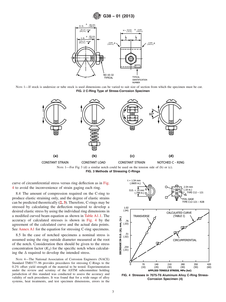
erations are discussed in Section 7.Atypical shop drawing for
3. Summary of Practice
the manufacture of a C-ring is shown in Fig. 2.
3.1 This practice involves the preparation of and the quan-
titative stressing of a C-ring stress-corrosion test specimen by
7. Stress Considerations
application of a bending load. Characteristics of the stress
7.1 The stress of principal interest in the C-ring specimen is
system and the distribution of stresses are discussed. Guidance
the circumferential stress. It should be recognized that this
is given for methods of exposure and inspection.
stressisnotuniform (2, 3).First,thereisagradientthroughthe
thickness, varying from a maximum tension on one surface to
4. Significance and Use
amaximumcompressionontheoppositesurface.Secondly,the
4.1 The C-ring is a versatile, economical specimen for
stress varies around the circumference of the C-ring from zero
quantitativelydeterminingthesusceptibilitytostress-corrosion
at each bolt hole to a maximum at the middle of the arc
opposite the stressing bolt; the nominal stress is present only
This practice is under the jurisdiction ofASTM Committee G01 on Corrosion
alongalineacrosstheringatthemiddleofthearc.Thus,when
of Metals and is the direct responsibility of Subcommittee G01.06 on Environmen-
the specimen is stressed by measuring the strain on the tension
tally Assisted Cracking.
surface of the C-ring, the strain gage should be positioned at
CurrenteditionapprovedMay1,2013.PublishedJuly2013.Originallyapproved
in 1973. Last previous edition approved in 2007 as G38-01 (2007). DOI:
10.1520/G0038-01R13.
AvailablefromNationalAssociationofCorrosionEngineers(NACE),P.O.Box Theboldfacenumbersinparenthesesrefertothelistofreferencesattheendof
218340, Houston, TX 77218–8340. this practice.
Copyright © ASTM International, 100 Barr Harbor Drive, PO Box C700, West Conshohocken, PA 19428-2959. United States
G38 − 01 (2013)
addition, the circumferential stress at the root of the notch will
be greater than the nominal stress and generally may be
expected to be in the plastic range.
7.4 The possibility of residual stress should always be
considered, especially when C-rings are machined from prod-
ucts that contain appreciable residual stress or when C-rings
over about 6.35 mm ( ⁄4 in.) thick are heat treated after being
machined. It is generally not advisable to heat treat finish-
machined C-rings because of the likelihood of developing
residual stresses in the ring.
NOTE 1—When specimens are exposed to corrosive media at elevated
temperatures, the possibility of relaxation of stress during the exposure
period should be investigated. Relaxation can be estimated from known
creep data for both the ring and the stressing bolt.
7.5 AnadvantageoftheC-ringisthatitcanbestressedwith
high precision and bias by application of a measured deflec-
tion.Thesourcesoferrorinstressingarethosethatareinherent
with the use of measuring instruments (micrometers, strain
gages, etc.) as discussed in 7.2 – 7.4 and Annex A1.
7.6 The calculated stress applies only to the state of stress
before initiation of cracks. Once cracking has initiated the
stress at the tip of the crack, as well as in uncracked areas, has
changed.
8. Stressing Methods
8.1 The C-ring, as generally used, is a constant-strain
specimen with tensile stress produced on the exterior of the
ring by tightening a bolt centered on the diameter of the ring.
FIG. 1 Sampling Procedure for Testing Various Products
However,anearlyconstantloadcanbedevelopedbytheuseof
a calibrated spring placed on the loading bolt. C-rings also can
be stressed in the reverse direction by spreading the ring and
the middle of the arc in order to indicate the maximum strain.
creatingatensilestressontheinsidesurface.Thesemethodsof
Thirdly,thecircumferentialstressmayvaryacrossthewidthof
stressing are illustrated in Fig. 3. Proper choice of a minimum
the ring, the extent of the variation depending on the width-
bolt diameter or a spring constant is, of course, required to
to-thickness and diameter-to-thickness ratios of the C-ring. In
assure achieving true constant strain or constant load stressing.
general,whenloadedasshowninFig.3(a,b),thetensilestress
8.2 The most accurate stressing procedure is to attach
on the outer surface will be greater at the extreme edge than at
circumferential and transverse electrical strain gages to the
thecenter,whilewhenloadedasshowninFig.3(c),thetensile
surfacestressedintensionandtotightentheboltuntilthestrain
stress on the inner surface will be less at the edge than at the
measurements indicate the desired circumferential stress. The
center (4).
circumferential(σ )andtransverse(σ ),stressesarecalculated
C T
7.2 Another characteristic of the stress system in the C-ring
as follows:
is the presence of biaxial stresses; that is, transverse as well as
σ 5 E/~1 2 µ !·~ε 1µε !, and
C C T
circumferential stresses are developed on the critical test
σ 5 E/ 1 2 µ · ε 1µε
~ ! ~ !
T T C
section.The transverse stress will vary from a maximum at the
mid-widthtozeroattheedges,andwillbethesamesignasthe
where:
circumferential stress. In general, the transverse stress may be
E = Young’s modulus of elasticity,
expected to decrease with decreasing width to thickness and
µ = Poisson’s ratio,
increasingdiametertothicknessratios.Anexampleisshownin
ε = circumferential strain, and
C
Fig. 4 where the transverse tensile stress at the mid-width of a
ε = transverse strain.
T
19.00 mm (0.748 in.) outside diameter by 1.537 mm (0.0605 NOTE2—Whenusingelectricalstraingageswiththin-walledC-rings,a
correction should be allowed for the displacement of the gage from the
in.)thickby19.0mm(0.75in.)wideC-ringofaluminumalloy
surface of the ring. All traces of the gage and the adhesive must be
7075-T6 was equal to about one third of the circumferential
removed from the C-ring before it is exposed.
tensile stress. In this example the circumferential stress was
NOTE 3—Stresses may be calculated from measured strains using the
uniform over most of the width of the C-ring; measurements
modulus of elasticity, provided the stresses and strains do not exceed the
were not made at the extreme edge.
proportional limit.
7.3 In the case of the notched C-ring (Fig. 3(d)) a triaxial 8.3 When several rings of the same alloy and dimensions
stress state is present adjacent to the root of the notch (5).In are to be loaded, it is convenient to determine a calibration
G38 − 01 (2013)
NOTE 1—If stock is undersize or tube stock is used dimensions can be varied to suit size of section from which the specimen must be cut.
FIG. 2 C-Ring Type of Stress-Corrosion Specimen
NOTE 1—For Fig 3 (d) a similar notch could be used on the tension side of (b) or (c).
FIG. 3 Methods of Stressing C-Rings
curve of circumferential stress versus ring deflection as in Fig.
4 to avoid the inconvenience of strain gaging each ring.
8.4 The amount of compression required on the C-ring to
produce elastic straining only, and the degree of elastic strains
canbepredictedtheoretically (2, 3).Therefore,C-ringsmaybe
stressed by calculating the deflection required to develop a
desiredelasticstressbyusingtheindividualringdimensionsin
a modified curved beam equation as shown in TableA1.1.The
accuracy of calculated stresses is shown in Fig. 4 by the
agreement of the calculated curve and the actual data points.
See AnnexA1 for the equation for stressing C-ring specimens.
8.5 In the case of notched specimens a nominal stress is
assumed using the ring outside diameter measured at the root
of the notch. Consideration then should be given to the stress
concentration factor (K ) for the specific notch when calculat-
T
ing the ∆ required to develop the intended stress.
NOTE 4—The National Association of Corrosion Engineers (NACE)
Standard TM0177–96 provides procedures for stressing C-Rings to the
0.2% offset yield strength of the material to be tested. Experimentation
under the review and scrutiny of the ASTM subcommittee holding
jurisdiction of this standard was conducted to assess the accuracy and
FIG. 4 Stresses in 7075-T6 Aluminum Alloy C-Ring Stress-
validity of such procedures. It was found that for a wide range of alloy
Corrosion Specimen (4)
systems, heat treatments, and test specimen dimensions, errors in the
G38 − 01 (2013)
FIG. 5 Protection Against Galvanic Effects
target strain associated with the 0.2% offset yield strength occurred which
12. Exposure Methods
wouldbeofsignificance.However,itwasalsodeterminedthatinallcases
the actual strain realized following the procedures exceeded that associ- 12.1 The C-ring, because of its small size and the simple
ated with the 0.2% offset yield stress, rendering results following such
methods of stressing, can be exposed to almost any kind of
procedures conservative from an engineering analysis standpoint.
corrosiveenvironment (6).Thespecimensshouldbesupported
insuchawaythatnothingexceptthecorrosivemediumcomes
9. Machining
in contact with the critically stressed area. No part of an
9.1 When rings are machined from solid stock, precautions
exposure rack should be allowed to touch the surface or the
should be taken to avoid practices that overheat, plastically
edges of the critically stressed region.
deform, or develop residual stress in the metal surface.
12.2 Care must be exercised to avoid galvanic effects
Machining should be done in stages so that the final cut leaves
betweentheC-ring,thestressingbolt,andexposureracks.Itis
theprincipalsurfacewithacleanfinishof0.7µm(30µin.)rms
essential also to prevent crevice corrosion that could develop
or better. Necessary machining sequences, type of tool, feed
corrosion products between ring and bolt and alter the stress in
rate, etc., depend upon the alloy and temper of the test piece.
the C-ring. Protection can readily be applied by means of
Lapping, mechanical polishing, and similar operations that
suitable coatings or by insulating bushing as shown in Fig. 5.
produce flow of the metal should be avoided.
Consideration must be given to the selection of coatings or
10. Surface Preparation insulators that will neither contaminate the corroding medium
nor be deteriorated by it. An insulating bushing, for example,
10.1 A high-quality machined surface is the most desirable
that would deteriorate or creep, and thus allow the stress in the
for corrosion test purposes unless one wants to test the
specimen to decrease, would be unsatisfactory.
as-fabricated surface of a tube or bar; it should, of course, be
degreased before exposing the specimen. In order to remove
NOTE 5—Specimens should be placed in the intended corrosive
heat treat films or thin layers of surface metal that may have
environment as soon as possible after being stressed, as some alloys may
become distorted during machining, chemical or electrochemi-
crack in moderately humid air.
cal etches may be used. The choice of such a treatment will NOTE 6—Hemispheric glazed ceramic insulators (S-151 Steatite) are
excellentforuseoutdoorsandinneutralaqueoussolutions. Beeswax,and
depend upon the alloy of the test piece. Care should be
other adherent wax-type coatings, are suitable for room temperature tests
exercised to choose an etchant that will not selectively attack
in aqueous solutions. For tests in acidic or alkaline solutions, fast drying
constituents in the metal or will not deposit undesirable
vinyl-type lacquers have been used successfully; an example is an
residues on the surface. Etching or pickling should not be used
electroplaters stop-off.
for alloys that may undergo hydrogen embrittlement.
12.3 Determination of cracking time is a subjective proce-
10.2 It is generally the best procedure to complete the
dure involving visual examination that under some conditions
surface preparation before the C-ring is stressed except for a
canbeverydifficult,asnotedinSection13,anddependsonthe
possible final degreasing of the critically stressed area.
skill and experience
...
Questions, Comments and Discussion
Ask us and Technical Secretary will try to provide an answer. You can facilitate discussion about the standard in here.