


ASTM E781-86(2015)
(Practice)Standard Practice for Evaluating Absorptive Solar Receiver Materials When Exposed to Conditions Simulating Stagnation in Solar Collectors With Cover Plates
Standard Practice for Evaluating Absorptive Solar Receiver Materials When<brk/> Exposed to Conditions Simulating Stagnation in Solar<brk/> Collectors With Cover Plates
SIGNIFICANCE AND USE
4.1 Although this practice is intended for evaluating solar absorber materials and coatings used in flat-plate collectors, no single procedure can duplicate the wide range of temperatures and environmental conditions to which these materials may be exposed during in-service conditions.
4.2 This practice is intended as a screening test for absorber materials and coatings. All conditions are chosen to be representative of those encountered in solar collectors with single cover plates and with no added means of limiting the temperature during stagnation conditions.
4.3 This practice uses exposure in a simulated collector with a single cover plate. Although collectors with additional cover plates will produce higher temperatures at stagnation, this procedure is considered to provide adequate thermal testing for most applications.
Note 1: Mathematical modelling has shown that a selective absorber, single glazed flat-plate solar collector can attain absorber plate stagnation temperatures as high as 226°C (437°F) with an ambient temperature of 37.8°C (100°F) and zero wind velocity; and a double glazed one as high as 245°C (482°F) under these conditions. The same configuration solar collector with a nonselective absorber can attain absorber stagnation temperatures as high as 146°C (284°F), if single glazed, and 185°C (360°F), if double glazed, with the same environmental conditions, (see “Performance Criteria for Solar Heating and Cooling Systems in Commercial Buildings,” NBS Technical Note 11874).
4.4 This practice evaluates the thermal stability of absorber materials. It does not evaluate the moisture stability of absorber materials used in actual solar collectors exposed outdoors. Moisture intrusion into solar collectors is a frequent occurrence in addition to condensation caused by diurnal breathing.
4.5 This practice differentiates between the testing of spectrally selective absorbers and nonselective absorbers.
4.5.1 Testing Spectrally Selective Absor...
SCOPE
1.1 This practice covers a test procedure for evaluating absorptive solar receiver materials and coatings when exposed to sunlight under cover plate(s) for long durations. This practice is intended to evaluate the exposure resistance of absorber materials and coatings used in flat-plate collectors where maximum nonoperational stagnation temperatures will be approximately 200°C (392°F).
1.2 This practice shall not apply to receiver materials used in solar collectors without covers (unglazed) or in evacuated collectors, that is, those that use a vacuum to suppress convective and conductive thermal losses.
1.3 The values stated in SI units are to be regarded as the standard.
1.4 This standard does not purport to address all of the safety concerns, if any, associated with its use. It is the responsibility of the user of this standard to establish appropriate safety and health practices and determine the applicability of regulatory limitations prior to use.
General Information
Buy Standard
Standards Content (Sample)
NOTICE: This standard has either been superseded and replaced by a new version or withdrawn.
Contact ASTM International (www.astm.org) for the latest information
Designation: E781 − 86 (Reapproved 2015)
Standard Practice for
Evaluating Absorptive Solar Receiver Materials When
Exposed to Conditions Simulating Stagnation in Solar
Collectors with Cover Plates
This standard is issued under the fixed designation E781; the number immediately following the designation indicates the year of
original adoption or, in the case of revision, the year of last revision. A number in parentheses indicates the year of last reapproval. A
superscript epsilon (´) indicates an editorial change since the last revision or reapproval.
1. Scope D1898 Practice for Sampling of Plastics (Withdrawn 1998)
E408 Test Methods for Total Normal Emittance of Surfaces
1.1 This practice covers a test procedure for evaluating
Using Inspection-Meter Techniques
absorptive solar receiver materials and coatings when exposed
E434 Test Method for Calorimetric Determination of Hemi-
to sunlight under cover plate(s) for long durations. This
spherical Emittance and the Ratio of Solar Absorptance to
practice is intended to evaluate the exposure resistance of
Hemispherical Emittance Using Solar Simulation
absorber materials and coatings used in flat-plate collectors
E772 Terminology of Solar Energy Conversion
where maximum nonoperational stagnation temperatures will
E903 Test Method for Solar Absorptance, Reflectance, and
be approximately 200°C (392°F).
Transmittance of Materials Using Integrating Spheres
1.2 This practice shall not apply to receiver materials used
E962
in solar collectors without covers (unglazed) or in evacuated
collectors, that is, those that use a vacuum to suppress
3. Terminology
convective and conductive thermal losses.
3.1 Definitions:
1.3 The values stated in SI units are to be regarded as the
3.1.1 See Terminology E772 for definitions.
standard.
4. Significance and Use
1.4 This standard does not purport to address all of the
4.1 Although this practice is intended for evaluating solar
safety concerns, if any, associated with its use. It is the
absorber materials and coatings used in flat-plate collectors, no
responsibility of the user of this standard to establish appro-
single procedure can duplicate the wide range of temperatures
priate safety, health, and environmental practices and deter-
and environmental conditions to which these materials may be
mine the applicability of regulatory limitations prior to use.
exposed during in-service conditions.
1.5 This international standard was developed in accor-
dance with internationally recognized principles on standard-
4.2 This practice is intended as a screening test for absorber
ization established in the Decision on Principles for the
materials and coatings. All conditions are chosen to be repre-
Development of International Standards, Guides and Recom-
sentative of those encountered in solar collectors with single
mendations issued by the World Trade Organization Technical
cover plates and with no added means of limiting the tempera-
Barriers to Trade (TBT) Committee.
ture during stagnation conditions.
4.3 This practice uses exposure in a simulated collector with
2. Referenced Documents
a single cover plate. Although collectors with additional cover
2.1 ASTM Standards:
plates will produce higher temperatures at stagnation, this
B537 Practice for Rating of Electroplated Panels Subjected
procedure is considered to provide adequate thermal testing for
to Atmospheric Exposure
most applications.
NOTE 1—Mathematical modelling has shown that a selective absorber,
single glazed flat-plate solar collector can attain absorber plate stagnation
This practice is under the jurisdiction of ASTM Committee E44 on Solar,
temperatures as high as 226°C (437°F) with an ambient temperature of
Geothermal and Other Alternative Energy Sources and is the direct responsibility of
37.8°C (100°F) and zero wind velocity; and a double glazed one as high
Subcommittee E44.20 on Optical Materials for Solar Applications.
as 245°C (482°F) under these conditions. The same configuration solar
Current edition approved March 1, 2015. Published April 2015. Originally
collector with a nonselective absorber can attain absorber stagnation
approved in 1981. Last previous edition approved in 2009 as E781 – 86 (2009).
temperatures as high as 146°C (284°F), if single glazed, and 185°C
DOI: 10.1520/E0781-86R15.
For referenced ASTM standards, visit the ASTM website, www.astm.org, or
contact ASTM Customer Service at service@astm.org. For Annual Book of ASTM
Standards volume information, refer to the standard’s Document Summary page on The last approved version of this historical standard is referenced on
the ASTM website. www.astm.org.
Copyright © ASTM International, 100 Barr Harbor Drive, PO Box C700, West Conshohocken, PA 19428-2959. United States
E781 − 86 (2015)
(360°F), if double glazed, with the same environmental conditions, (see
eliminating contamination of the cover plate and the samples
“Performance Criteria for Solar Heating and Cooling Systems in Com-
during actual testing periods and is especially important where
mercial Buildings,” NBS Technical Note 1187 ).
coatings employing organic components are used. If the cover
4.4 This practice evaluates the thermal stability of absorber
plate is in place during this outgassing procedure, it shall be
materials. It does not evaluate the moisture stability of absorber
cleaned before the box is put into service in order to restore its
materials used in actual solar collectors exposed outdoors.
original transmittance.
Moisture intrusion into solar collectors is a frequent occurrence
5.2 Cover Plate—The box shall have a single cover plate
in addition to condensation caused by diurnal breathing.
that is glazed and hinged to provide access.
4.5 This practice differentiates between the testing of spec-
5.2.1 Two types of cover plate materials may be used:
trally selective absorbers and nonselective absorbers.
5.2.1.1 Type I—Tempered low-iron glass with spectral char-
4.5.1 Testing Spectrally Selective Absorber Coatings and
acteristics approximating those shown in Fig. 2.
Materials—Spectrally selective solar absorptive coatings and
5.2.1.2 Type II—Alternative types of solar transmitting glass
materials require testing in a covered enclosure that contains a
or plastic materials might be used for the cover plate if the
selectively coated sample mounting plate, such that the enclo-
absorber is to be used under that material.
sure and mounting plate simulate the temperature conditions of
5.2.2 The solar-weighted transmittance values of the cover
a selective flat-plate collector exposed under stagnation condi-
plate test patches (5.2.3 and 5.2.4) shall remain above the
tions.
indicated percentage of their initial values in the following
4.5.2 Testing Nonselective Coatings and Materials—
wavelength regions:
Spectrally nonselective solar absorptive coatings and materials
300 to 400 nm − 90 %
require testing in a covered enclosure that contains a nonse-
400 to 2100 nm − 95 %
lective coated sample mounting plate, such that the enclosure
5.2.3 An easily removable test patch of the cover material
and mounting plate simulate the temperature conditions of a
measuring 50 by 50 mm (2 by 2 in.) shall be fastened onto the
covered, nonselective flat-plate collector exposed under stag-
inner surface of the transparent cover plate in or near one lower
nation conditions.
corner. By periodically measuring the transmittance of this test
patch, an indication of the effect of any condensable effluents
5. Test Apparatus
on the cover material can be monitored.
5.1 Test Enclosure—(Fig. 1), consisting of a box that ap-
5.2.4 An easily removable specimen of the cover plate
proximates the dimensions of a typical flat-plate solar collector
material measuring 50 by 50 mm (2 by 2 in.) should also be
and shall have minimum dimensions of 0.75 by 1.5 by 0.1 m
mounted directly on an exterior upper corner of the cover plate
(29 by 60 by 4 in.) deep. The box should be constructed of
to monitor the effects of atmospheric contamination and
materials that are impervious to moisture. Wood should not be
ultraviolet degradation. These effects are generally more severe
used for construction of the box. Care shall be taken to prevent
for plastic materials than for glass.
water leakage at joints, seams, and seals.
5.3 Seals—A seal that does not outgas at the stagnation
5.1.1 Pre-Exposure of Test Box—Prior to use, the test
temperature should be used to make the box weather-resistant.
apparatus shall be placed in an operational environment where
5.4 Insulation—The bottom and sides of the enclosure shall
all components are allowed to equilibrate at the stagnation
be insulated to have a thermal conductance of less than 0.515
temperature for a sufficient length of time to allow for
2 2
W/(m ·K)(0.091 Btu/(h·ft ·°F)), that is, an R value of 11 or
outgassing of the components. This procedure may aid in
greater with materials that do not outgas at the stagnation
temperature.
Available from U.S. Government Printing Office Superintendent of Documents, 5.5 Sample Mounting Plate—A metallic mounting plate
732 N. Capitol St., NW, Mail Stop: SDE, Washington, DC 20401, http://
with lateral dimensions approximately the same as the internal
www.access.gpo.gov.
FIG. 1 Typical Cross Section of Exposure Test Apparatus
E781 − 86 (2015)
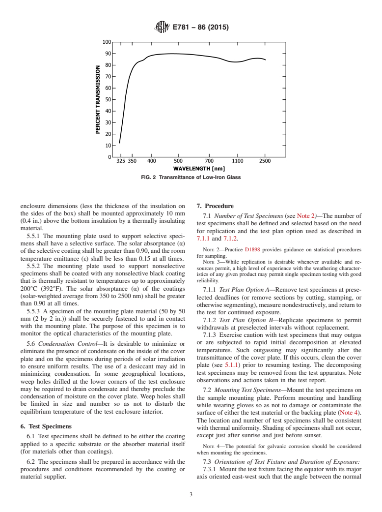
FIG. 2 Transmittance of Low-Iron Glass
enclosure dimensions (less the thickness of the insulation on 7. Procedure
the sides of the box) shall be mounted approximately 10 mm
7.1 Number of Test Specimens (see Note 2)—The number of
(0.4 in.) above the bottom insulation by a thermally insulating
test specimens shall be defined and selected based on the need
material.
for replication and the test plan option used as described in
5.5.1 The mounting plate used to support select
...
This document is not an ASTM standard and is intended only to provide the user of an ASTM standard an indication of what changes have been made to the previous version. Because
it may not be technically possible to adequately depict all changes accurately, ASTM recommends that users consult prior editions as appropriate. In all cases only the current version
of the standard as published by ASTM is to be considered the official document.
Designation: E781 − 86 (Reapproved 2009) E781 − 86 (Reapproved 2015)
Standard Practice for
Evaluating Absorptive Solar Receiver Materials When
Exposed to Conditions Simulating Stagnation in Solar
Collectors With Cover Plates
This standard is issued under the fixed designation E781; the number immediately following the designation indicates the year of
original adoption or, in the case of revision, the year of last revision. A number in parentheses indicates the year of last reapproval. A
superscript epsilon (´) indicates an editorial change since the last revision or reapproval.
1. Scope
1.1 This practice covers a test procedure for evaluating absorptive solar receiver materials and coatings when exposed to
sunlight under cover plate(s) for long durations. This practice is intended to evaluate the exposure resistance of absorber materials
and coatings used in flat-plate collectors where maximum nonoperational stagnation temperatures will be approximately 200°C
(392°F).
1.2 This practice shall not apply to receiver materials used in solar collectors without covers (unglazed) or in evacuated
collectors, that is, those that use a vacuum to suppress convective and conductive thermal losses.
1.3 The values stated in SI units are to be regarded as the standard.
1.4 This standard does not purport to address all of the safety concerns, if any, associated with its use. It is the responsibility
of the user of this standard to establish appropriate safety and health practices and determine the applicability of regulatory
limitations prior to use.
2. Referenced Documents
2.1 ASTM Standards:
B537 Practice for Rating of Electroplated Panels Subjected to Atmospheric Exposure
D1898 Practice for Sampling of Plastics (Withdrawn 1998)
E408 Test Methods for Total Normal Emittance of Surfaces Using Inspection-Meter Techniques
E434 Test Method for Calorimetric Determination of Hemispherical Emittance and the Ratio of Solar Absorptance to
Hemispherical Emittance Using Solar Simulation
E772 Terminology of Solar Energy Conversion
E903 Test Method for Solar Absorptance, Reflectance, and Transmittance of Materials Using Integrating Spheres
E962
3. Terminology
3.1 Definitions:
3.1.1 See Terminology E772 for definitions.
4. Significance and Use
4.1 Although this practice is intended for evaluating solar absorber materials and coatings used in flat-plate collectors, no single
procedure can duplicate the wide range of temperatures and environmental conditions to which these materials may be exposed
during in-service conditions.
4.2 This practice is intended as a screening test for absorber materials and coatings. All conditions are chosen to be
representative of those encountered in solar collectors with single cover plates and with no added means of limiting the temperature
during stagnation conditions.
This practice is under the jurisdiction of ASTM Committee E44 on Solar, Geothermal and Other Alternative Energy Sources and is the direct responsibility of
Subcommittee E44.05 on Solar Heating and Cooling Systems and Materials.
Current edition approved April 1, 2009March 1, 2015. Published June 2009April 2015. Originally approved in 1981. Last previous edition approved in 20032009 as
E781–86(2003).E781–86(2009). DOI: 10.1520/E0781-86R09.10.1520/E0781-86R15.
For referenced ASTM standards, visit the ASTM website, www.astm.org, or contact ASTM Customer Service at service@astm.org. For Annual Book of ASTM Standards
volume information, refer to the standard’s Document Summary page on the ASTM website.
The last approved version of this historical standard is referenced on www.astm.org.
Copyright © ASTM International, 100 Barr Harbor Drive, PO Box C700, West Conshohocken, PA 19428-2959. United States
E781 − 86 (2015)
4.3 This practice uses exposure in a simulated collector with a single cover plate. Although collectors with additional cover
plates will produce higher temperatures at stagnation, this procedure is considered to provide adequate thermal testing for most
applications.
NOTE 1—Mathematical modelling has shown that a selective absorber, single glazed flat-plate solar collector can attain absorber plate stagnation
temperatures as high as 226°C (437°F) with an ambient temperature of 37.8°C (100°F) and zero wind velocity; and a double glazed one as high as 245°C
(482°F) under these conditions. The same configuration solar collector with a nonselective absorber can attain absorber stagnation temperatures as high
as 146°C (284°F), if single glazed, and 185°C (360°F), if double glazed, with the same environmental conditions, (see “Performance Criteria for Solar
Heating and Cooling Systems in Commercial Buildings,” NBS Technical Note 1187 ).
4.4 This practice evaluates the thermal stability of absorber materials. It does not evaluate the moisture stability of absorber
materials used in actual solar collectors exposed outdoors. Moisture intrusion into solar collectors is a frequent occurrence in
addition to condensation caused by diurnal breathing.
4.5 This practice differentiates between the testing of spectrally selective absorbers and nonselective absorbers.
4.5.1 Testing Spectrally Selective Absorber Coatings and Materials—Spectrally selective solar absorptive coatings and
materials require testing in a covered enclosure that contains a selectively coated sample mounting plate, such that the enclosure
and mounting plate simulate the temperature conditions of a selective flat-plate collector exposed under stagnation conditions.
4.5.2 Testing Nonselective Coatings and Materials—Spectrally nonselective solar absorptive coatings and materials require
testing in a covered enclosure that contains a nonselective coated sample mounting plate, such that the enclosure and mounting
plate simulate the temperature conditions of a covered, nonselective flat-plate collector exposed under stagnation conditions.
5. Test Apparatus
5.1 Test Enclosure—(Fig. 1), consisting of a box that approximates the dimensions of a typical flat-plate solar collector and shall
have minimum dimensions of 0.75 by 1.5 by 0.1 m (29 by 60 by 4 in.) deep. The box should be constructed of materials that are
impervious to moisture. Wood should not be used for construction of the box. Care shall be taken to prevent water leakage at joints,
seams, and seals.
5.1.1 Pre-Exposure of Test Box—Prior to use, the test apparatus shall be placed in an operational environment where all
components are allowed to equilibrate at the stagnation temperature for a sufficient length of time to allow for outgassing of the
components. This procedure may aid in eliminating contamination of the cover plate and the samples during actual testing periods
and is especially important where coatings employing organic components are used. If the cover plate is in place during this
outgassing procedure, it shall be cleaned before the box is put into service in order to restore its original transmittance.
5.2 Cover Plate—The box shall have a single cover plate that is glazed and hinged to provide access.
5.2.1 Two types of cover plate materials may be used:
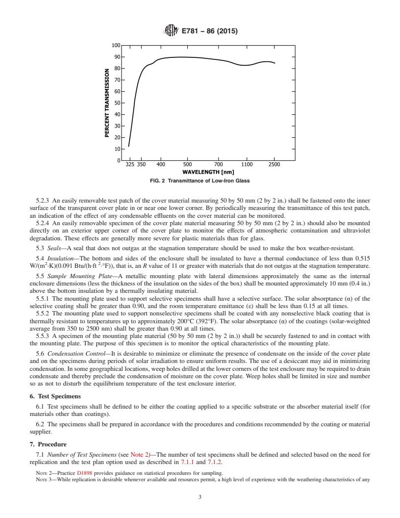
5.2.1.1 Type I—Tempered low-iron glass with spectral characteristics approximating those shown in Fig. 2.
5.2.1.2 Type II—Alternative types of solar transmitting glass or plastic materials might be used for the cover plate if the absorber
is to be used under that material.
5.2.2 The solar-weighted transmittance values of the cover plate test patches (5.2.3 and 5.2.4) shall remain above the indicated
percentage of their initial values in the following wavelength regions:
300 to 400 nm − 90 %
400 to 2100 nm − 95 %
Available from U.S. Government Printing Office Superintendent of Documents, 732 N. Capitol St., NW, Mail Stop: SDE, Washington, DC 20401, http://
www.access.gpo.gov.
FIG. 1 Typical Cross Section of Exposure Test Apparatus
E781 − 86 (2015)
FIG. 2 Transmittance of Low-Iron Glass
5.2.3 An easily removable test patch of the cover material measuring 50 by 50 mm (2 by 2 in.) shall be fastened onto the inner
surface of the transparent cover plate in or near one lower corner. By periodically measuring the transmittance of this test patch,
an indication of the effect of any condensable effluents on the cover material can be monitored.
5.2.4 An easily removable specimen of the cover plate material measuring 50 by 50 mm (2 by 2 in.) should also be mounted
directly on an exterior upper corner of the cover plate to monitor the effects of atmospheric contamination and ultraviolet
degradation. These effects are generally more severe for plastic materials than for glass.
5.3 Seals—A seal that does not outgas at the stagnation temperature should be used to make the box weather-resistant.
5.4 Insulation—The bottom and sides of the enclosure shall be insulated to have a thermal conductance of less than 0.515
2 2
W/(m ·K)(0.091 Btu/(h·ft ·°F)), that is, an R value of 11 or greater with materials that do not outgas at the stagnation temperature.
5.5 Sample Mounting Plate—A metallic mounting plate with lateral dimensions approximately the same as the internal
enclosure dimensions (less the thickness of the insulation on the sides of the box) shall be mounted approximately 10 mm (0.4 in.)
above the bottom insulation by a thermally insulating material.
5.5.1 The mounting plate used to support selective specimens shall have a selective surface. The solar absorptance (α) of the
selective coating shall be greater than 0.90, and the room temperature emittance (ε) shall be less tha
...
Questions, Comments and Discussion
Ask us and Technical Secretary will try to provide an answer. You can facilitate discussion about the standard in here.