


ASTM D7739-11(2016)
(Practice)Standard Practice for Thermal Oxidative Stability Measurement via Quartz Crystal Microbalance
Standard Practice for Thermal Oxidative Stability Measurement via Quartz Crystal Microbalance
SIGNIFICANCE AND USE
3.1 The tendency of a jet fuel to resist the formation of deposits at elevated temperature is indicative of its oxidative thermal stability. This practice provides a technique for the simultaneous determination of deposit formation and oxygen consumption during the thermal oxidation of jet fuels and other hydrocarbon liquids. The practice can be used to evaluate the thermal stability of fuels and to determine the efficacy of additives in inhibiting deposition or slowing oxidation, or both. A test temperature of 140 °C and run length up to 16 h has been found to be effective for the relative evaluation of fuels and fuel additives. This practice has also been employed for other hydrocarbon liquids, such as gasoline and diesel fuels, but additional safety issues may need to be addressed by the user.
SCOPE
1.1 This laboratory practice covers the quantitative determination of surface deposits produced during the thermal oxidation of gas turbine fuels by monitoring the oscillation frequency of a quartz crystal during thermal exposure. In this practice, “thermal oxidative stability” refers to the tendency of a fuel to resist surface deposit formation during heating.
1.2 The values stated in SI units are to be regarded as the standard. The values given in parentheses are for information only.
1.3 This standard does not purport to address all of the safety concerns, if any, associated with its use. It is the responsibility of the user of this standard to establish appropriate safety and health practices and determine the applicability of regulatory limitations prior to use.
General Information
Buy Standard
Standards Content (Sample)
NOTICE: This standard has either been superseded and replaced by a new version or withdrawn.
Contact ASTM International (www.astm.org) for the latest information
Designation: D7739 − 11 (Reapproved 2016) An American National Standard
Standard Practice for
Thermal Oxidative Stability Measurement via Quartz Crystal
Microbalance
This standard is issued under the fixed designation D7739; the number immediately following the designation indicates the year of
original adoption or, in the case of revision, the year of last revision. A number in parentheses indicates the year of last reapproval. A
superscript epsilon (´) indicates an editorial change since the last revision or reapproval.
1. Scope 3. Significance and Use
1.1 This laboratory practice covers the quantitative determi-
3.1 The tendency of a jet fuel to resist the formation of
nation of surface deposits produced during the thermal oxida-
deposits at elevated temperature is indicative of its oxidative
tion of gas turbine fuels by monitoring the oscillation fre-
thermal stability. This practice provides a technique for the
quency of a quartz crystal during thermal exposure. In this
simultaneous determination of deposit formation and oxygen
practice, “thermal oxidative stability” refers to the tendency of
consumptionduringthethermaloxidationofjetfuelsandother
a fuel to resist surface deposit formation during heating.
hydrocarbon liquids. The practice can be used to evaluate the
1.2 The values stated in SI units are to be regarded as the thermal stability of fuels and to determine the efficacy of
standard. The values given in parentheses are for information additivesininhibitingdepositionorslowingoxidation,orboth.
only.
Atesttemperatureof140 °Candrunlengthupto16 hhasbeen
found to be effective for the relative evaluation of fuels and
1.3 This standard does not purport to address all of the
fuel additives. This practice has also been employed for other
safety concerns, if any, associated with its use. It is the
hydrocarbon liquids, such as gasoline and diesel fuels, but
responsibility of the user of this standard to establish appro-
additional safety issues may need to be addressed by the user.
priate safety and health practices and determine the applica-
bility of regulatory limitations prior to use.
4. Apparatus
2. Summary of Practice
4.1 All dimensions without tolerance limits are nominal
2.1 A quartz crystal, fitted with gold electrodes, is fully values.
immersed in test fuel contained within a reactor. An oscillator
4.2 Reactor—A T316, 100 mL stainless steel reactor cylin-
circuit, connected to the crystal, supplies energy to excite the
der with an internal diameter of 5.23 cm (2.06 in.) and a depth
quartz crystal and monitors its resonant frequency (nominally
3,4
of 4.93 cm (1.94 in.). A T316 stainless steel reactor head
5 MHz) over time via a computer interface. The reactor is
with several openings (for example, gas inlet via dip tube, gas
equipped with a magnetic stir bar, pressure gauge/transducer,
release fitted with a dial gauge or pressure transducer,
oxygen sensor (not recommended for certain test conditions,
thermocouple, safety rupture disk, frequency signal
see 4.11), and thermocouple to monitor and control test
connection, sleeve for oxygen concentration probe). A
conditions. Prior to testing, the fuel is bubbled with the test gas
0.952 cm( ⁄8 in.)holeisdrilledinthecenterofthereactorhead
for 30 min to equilibrate.After equilibration, the reactor vessel
to accommodate the frequency signal connectors. This hole
is isolated and raised to test temperature and pressure. As
shall have a 0.952 cm ( ⁄8 in.) clearance from any adjacent
deposits accumulate on the crystal surface during the run, the
opening.
crystal frequency decreases. The shift in resonance frequency
can be quantitatively related, in real time, to surface deposit
4.3 SMACoaxial ConnectorAssembly—This assembly pro-
accumulation via a variation of the Sauerbrey equation.
vides the electronic connection through the reactor head to the
quartzcrystalandconsistsofseveralkeyparts(seeFig.1).The
cable from the oscillator (see 4.6) connects to a subminiature
This practice is under the jurisdiction of ASTM Committee D02 on Petroleum
Products, Liquid Fuels, and Lubricants and is the direct responsibility of Subcom-
mittee D02.J0.03 on Combustion and Thermal Properties.
Current edition approved April 1, 2016. Published May 2016. Originally The sole source of supply of the apparatus (Parr Instrument cylinder model
approved in 2011. Last previous edition approved in 2011 as D7739 – 11. DOI: #452HC8 (100 mL)) known to the committee at this time is Parr Instrument
10.1520/D7739-11R16. Company, 211 Fifty-Third St., Moline, IL 61265-1770.
2 4
Klavetter, E. A., Martin, S. J., and Wessendorf, K. O., “Monitoring Jet Fuel If you are aware of alternative suppliers, please provide this information to
Thermal Stability Using a Quartz Crystal Microbalance,” Energy & Fuels, Vol 3, ASTM International Headquarters. Your comments will receive careful consider-
1993, pp. 582-588. ation at a meeting of the responsible technical committee, which you may attend.
Copyright © ASTM International, 100 Barr Harbor Drive, PO Box C700, West Conshohocken, PA 19428-2959. United States
D7739 − 11 (2016)
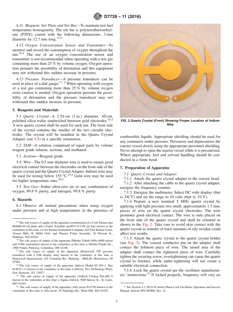
FIG. 1 SMA Coaxial Connector Assembly
5,4
version A (SMA) adapter plug. The SMA adapter plug the frequency controlling element of the oscillator.The adapter
6,4
connects to two male SMA connectors. The male SMA is based on a design by the Sandia National Laboratories and
10,4
connectors are first welded together, and then laser welded in may be purchased commercially. The insulator between the
7,4
place on both sides of the reactor head. Amating set of SMA adapter and the coaxial conductor pin may be fashioned by
11,4
connectors (male and female) was not used since these were machining or carefully fracturing ceramic tubing.
notavailablein0.952 cm( ⁄8 in.)diameter.Thethreadedendof
4.7 Oscillator—A phase lock oscillator that measures the
the SMAconnector on the bottom of the reactor head connects
frequency of the quartz crystal and provides a DC voltage
to the Quartz Crystal Adapter (see 4.5).
signal proportional to the conductance of the crystal. Suitable
12,4
4.4 ReactorHeater—Openbottombandheaterusedtobring for quartz crystals with a resonance frequency of 5 MHz.
8,4
test fuel to temperature.
4.8 FrequencyCounter—Tomeasurethefrequencyfromthe
13,4
4.5 Heater Controller—Proportional-integral-derivative oscillator. Frequency resolution shall be 60.1 Hz.
(PID) controller for regulating the open bottom reactor band
4.9 Multimeter/Data Acquisition System (DAS)—Measures
9,4
heater. A second heater controller may be used as a high
the conductance voltage, pressure, temperature, and other
temperature safety cut-off should the outside skin temperature 14,4
monitored parameters and transmits data to a computer.
of the reactor exceed a preset limit.
4.10 Thermocouples—K-type used to measure test fuel
4.6 Quartz Crystal Adapter—Required to both properly
temperature and outside reactor skin temperature (if so
align the quartz crystal and suspend the quartz crystal in the
equipped).
test fuel. Proper installation of the quartz crystal in the adapter
will complete an electrical circuit in which the quartz crystal is
The sole source of supply of the apparatus (part numbers 950132, 950133,
The sole source of supply of the apparatus (Part No. 3037M-1) known to the 950135 through 950138) known to the committee at this time is Raytheon Ktech,
committee at this time is Coaxial Components Corp., 10 Davinci Dr., Bohemia, NY 1300 Eubank Blvd. SE, Albuquerque, NM 87123.
11716-2601. The sole source of supply of the apparatus (Part No. R1201) known to the
The sole source of supply of the apparatus (Part No. 9251000) known to the committee at this time is Scientific Instrument Services, Inc., 1027 Old York Road.
committee at this time is Insulator Seal Inc., 6460 Parkland Dr., Sarasota, FL Ringoes, NJ 08551-1054.
34243-4036. The sole source of supply of the apparatus (Inficon PLO-10i phase lock
The sole source of supply of the apparatus (laser welding) known to the oscillator) known to the committee at this time is Inficon, Two Technology Place,
committee at this time is Precision Joining Technologies, Miamisburg, OH. East Syracuse, NY 13057.
8 13
The sole source of supply of the apparatus (Parr Instruments Model A2235 The sole source of supply of the apparatus (Agilent Models #53131A or
HC2EB, 110 VAC and A865HC11EB) known to the committee at this time is Parr 53181A) known to the committee at this time is Agilent Technologies, Inc., 5301
Instrument Company, 211 Fifty-Third St., Moline, IL 61265-1770. Stevens Creek Blvd., Santa Clara, CA 95051.
9 14
The sole source of supply of the apparatus (Eurotherm 2216E, Cal 9500P, and The sole source of supply of the apparatus (Keithley Model #2700) known to
Parr 4842 controllers) known to the committee at this time is Parr Instrument the committee at this time is Keithley Instruments, Inc., 28775 Aurora Rd.,
Company, 211 Fifty-Third St., Moline, IL 61265-1770. Cleveland, OH 44139.
D7739 − 11 (2016)
4.11 MagneticStirPlateandStirBar—To maintain test fuel
temperature homogeneity. The stir bar is polytetrafluoroethyl-
ene (PTFE) coated with the following dimensions, 3 mm
15,4
diameter by 12.7 mm long.
4.12 Oxygen Concentration Sensor and Transmitter—To
monitor and record the consumption of oxygen throughout the
16,4
run. The use of an oxygen concentration sensor and
transmitter is not recommended when operating with a test gas
containing more than 25 % by volume oxygen. Oxygen opera-
tion presents the possibility of detonation and this equipment
may not withstand this sudden increase in pressure.
4.13 Pressure Transducer—A pressure transducer can be
17, 4
used in place of a dial gauge. When operating with oxygen
or a test gas containing more than 25 % by volume oxygen
extra caution is needed. Oxygen operation presents the possi-
bility of detonation and the pressure transducer may not
withstand this sudden increase in pressure.
5. Reagents and Materials
5.1 Quartz Crystal—A 2.54 cm (1 in.) diameter, AT-cut,
18,4
polished silica wafer sandwiched between gold electrodes. FIG. 2 Quartz Crystal (Front) Showing Proper Location of Indium
Wire
Anew quartz crystal shall be used for each run. The front side
of the crystal contains the smaller of the two circular elec-
trodes. The crystal will be installed in the Quartz Crystal
combustible liquids. Appropriate shielding should be used for
Adapter (see 4.5) in a specific orientation.
any containers
...
This document is not an ASTM standard and is intended only to provide the user of an ASTM standard an indication of what changes have been made to the previous version. Because
it may not be technically possible to adequately depict all changes accurately, ASTM recommends that users consult prior editions as appropriate. In all cases only the current version
of the standard as published by ASTM is to be considered the official document.
Designation: D7739 − 11 D7739 − 11 (Reapproved 2016) An American National Standard
Standard Practice for
Thermal Oxidative Stability Measurement via Quartz Crystal
Microbalance
This standard is issued under the fixed designation D7739; the number immediately following the designation indicates the year of
original adoption or, in the case of revision, the year of last revision. A number in parentheses indicates the year of last reapproval. A
superscript epsilon (´) indicates an editorial change since the last revision or reapproval.
1. Scope
1.1 This laboratory practice covers the quantitative determination of surface deposits produced during the thermal oxidation of
gas turbine fuels by monitoring the oscillation frequency of a quartz crystal during thermal exposure. In this practice, “thermal
oxidative stability” refers to the tendency of a fuel to resist surface deposit formation during heating.
1.2 The values stated in SI units are to be regarded as the standard. The values given in parentheses are for information only.
1.3 This standard does not purport to address all of the safety concerns, if any, associated with its use. It is the responsibility
of the user of this standard to establish appropriate safety and health practices and determine the applicability of regulatory
limitations prior to use.
2. Summary of Practice
2.1 A quartz crystal, fitted with gold electrodes, is fully immersed in test fuel contained within a reactor. An oscillator circuit,
connected to the crystal, supplies energy to excite the quartz crystal and monitors its resonant frequency (nominally 5 MHz)
5 MHz) over time via a computer interface. The reactor is equipped with a magnetic stir bar, pressure gauge/transducer, oxygen
sensor (not recommended for certain test conditions, see 4.11), and thermocouple to monitor and control test conditions. Prior to
testing, the fuel is bubbled with the test gas for 30 min 30 min to equilibrate. After equilibration, the reactor vessel is isolated and
raised to test temperature and pressure. As deposits accumulate on the crystal surface during the run, the crystal frequency
decreases. The shift in resonance frequency can be quantitatively related, in real time, to surface deposit accumulation via a
variation of the Sauerbrey equation.
3. Significance and Use
3.1 The tendency of a jet fuel to resist the formation of deposits at elevated temperature is indicative of its oxidative thermal
stability. This practice provides a technique for the simultaneous determination of deposit formation and oxygen consumption
during the thermal oxidation of jet fuels and other hydrocarbon liquids. The practice can be used to evaluate the thermal stability
of fuels and to determine the efficacy of additives in inhibiting deposition or slowing oxidation, or both. A test temperature of
140°C140 °C and run length up to 16 h 16 h has been found to be effective for the relative evaluation of fuels and fuel additives.
This practice has also been employed for other hydrocarbon liquids, such as gasoline and diesel fuels, but additional safety issues
may need to be addressed by the user.
4. Apparatus
4.1 All dimensions without tolerance limits are nominal values.
4.2 Reactor—A T316, 100 mL 100 mL stainless steel reactor cylinder with an internal diameter of 5.23 cm (2.06 in.) 5.23 cm
3,4
(2.06 in.) and a depth of 4.93 cm (1.94 in.).4.93 cm (1.94 in.). A T316 stainless steel reactor head with several openings (for
example, gas inlet via dip tube, gas release fitted with a dial gauge or pressure transducer, thermocouple, safety rupture disk,
This practice is under the jurisdiction of ASTM Committee D02 on Petroleum Products Products, Liquid Fuels, and Lubricants and is the direct responsibility of
Subcommittee D02.J0.03 on Combustion and Thermal Properties.
Current edition approved June 1, 2011April 1, 2016. Published August 2011May 2016. Originally approved in 2011. Last previous edition approved in 2011 as D7739 – 11.
DOI: 10.1520/D7739–11.10.1520/D7739-11R16.
Klavetter, E. A., Martin, S. J., and Wessendorf, K. O., “Monitoring Jet Fuel Thermal Stability Using a Quartz Crystal Microbalance,” Energy & Fuels, Vol 3, 1993, pp.
582-588.
The sole source of supply of the apparatus (Parr Instrument cylinder model #452HC8 (100 mL)) known to the committee at this time is Parr Instrument Company, 211
Fifty-Third St., Moline, IL 61265-1770.
If you are aware of alternative suppliers, please provide this information to ASTM International Headquarters. Your comments will receive careful consideration at a
meeting of the responsible technical committee, which you may attend.
Copyright © ASTM International, 100 Barr Harbor Drive, PO Box C700, West Conshohocken, PA 19428-2959. United States
D7739 − 11 (2016)
FIG. 1 SMA Coaxial Connector Assembly
frequency signal connection, sleeve for oxygen concentration probe). A 0.952 cm0.952 cm ( ⁄8 (3/8 in.) in.) hole is drilled in the
center of the reactor head to accommodate the frequency signal connectors. This hole shall have a 0.952 cm0.952 cm ( ⁄8 (3/8 in.)
in.) clearance from any adjacent opening.
4.3 SMA Coaxial Connector Assembly—This assembly provides the electronic connection through the reactor head to the quartz
crystal and consists of several key parts (see Fig. 1). The cable from the oscillator (see 4.6) connects to a subminiature version
5,4 6,4
A (SMA) adapter plug. The SMA adapter plug connects to two male SMA connectors. The male SMA connectors are first
7,4
welded together, and then laser welded in place on both sides of the reactor head. A mating set of SMA connectors (male and
female) was not used since these were not available in 0.952 cm0.952 cm ( ⁄8 (3/8 in.) in.) diameter. The threaded end of the SMA
connector on the bottom of the reactor head connects to the Quartz Crystal Adapter (see 4.5).
8,4
4.4 Reactor Heater—Open bottom band heater used to bring test fuel to temperature.
9,4
4.5 Heater Controller—Proportional-integral-derivative (PID) controller for regulating the open bottom reactor band heater.
A second heater controller may be used as a high temperature safety cut-off should the outside skin temperature of the reactor
exceed a preset limit.
4.6 Quartz Crystal Adapter—Required to both properly align the quartz crystal and suspend the quartz crystal in the test fuel.
Proper installation of the quartz crystal in the adapter will complete an electrical circuit in which the quartz crystal is the frequency
controlling element of the oscillator. The adapter is based on a design by the Sandia National Laboratories and may be purchased
10,4
commercially. The insulator between the adapter and the coaxial conductor pin may be fashioned by machining or carefully
11,4
fracturing ceramic tubing.
The sole source of supply of the apparatus (Part No. 3037M-1) known to the committee at this time is Coaxial Components Corp., 10 Davinci Dr., Bohemia, NY
11716-2601.
The sole source of supply of the apparatus (Part No. 9251000) known to the committee at this time is Insulator Seal Inc., 6460 Parkland Dr., Sarasota, FL 34243-4036.
The sole source of supply of the apparatus (laser welding) known to the committee at this time is Precision Joining Technologies, Miamisburg, OH.
The sole source of supply of the apparatus (Parr Instruments Model A2235 HC2EB, 110 VAC and A865HC11EB) known to the committee at this time is Parr Instrument
Company, 211 Fifty-Third St., Moline, IL 61265-1770.
The sole source of supply of the apparatus (Eurotherm 2216E, Cal 9500P, and Parr 4842 controllers) known to the committee at this time is Parr Instrument Company,
211 Fifty-Third St., Moline, IL 61265-1770.
The sole source of supply of the apparatus (part numbers 950132, 950133, 950135 through 950138) known to the committee at this time is Raytheon Ktech, 1300 Eubank
Blvd. SE, Albuquerque, NM 87123.
The sole source of supply of the apparatus (Part No. R1201) known to the committee at this time is Scientific Instrument Services, Inc., 1027 Old York Road. Ringoes,
NJ 08551-1054.
D7739 − 11 (2016)
4.7 Oscillator—A phase lock oscillator that measures the frequency of the quartz crystal and provides a DC voltage signal
12,4
proportional to the conductance of the crystal. Suitable for quartz crystals with a resonance frequency of 5 MHz.
13,4
4.8 Frequency Counter—To measure the frequency from the oscillator. Frequency resolution shall be 60.1 Hz.60.1 Hz.
4.9 Multimeter/Data Acquisition System (DAS)—Measures the conductance voltage, pressure, temperature, and other monitored
14,4
parameters and transmits data to a computer.
4.10 Thermocouples—K-type used to measure test fuel temperature and outside reactor skin temperature (if so equipped).
4.11 Magnetic Stir Plate and Stir Bar—To maintain test fuel temperature homogeneity. The stir bar is polytetrafluoroethylene
15,4
(PTFE) coated with the following dimensions, 3 mm 3 mm diameter by 12.7 mm 12.7 mm long.
16,4
4.12 Oxygen Concentration Sensor and Transmitter—To monitor and record the consumption of oxygen throughout the run.
The use of an oxygen concentration sensor and transmitter is not recommended when operating with a test gas containing more
than 25 vol% 25 % by volume oxygen. Oxygen operation presents the possibility of detonation and this equipment may not
withstand this sudden increase in pressure.
17, 4
4.13 Pressure Transducer—A pressure transducer can be used in place of a dial gauge. When operating with oxygen or a
test gas containing more than 25 vol% 25 % by volume oxygen extra caution is needed. Oxygen operation presents the possibility
of detonation and the pressure transducer may not withstand this sudden increase in pressure.
5. Reagents and Materials
5.1 Quartz Crystal—A 2.54 cm (1 in.) 2.54 cm (1 in.) diameter, AT-cut, polished silica wafer sandwiched between gold
18,4
electrodes. A new quartz crystal shall be used for each run. The front side of the crystal contains the smaller of the two circular
electrodes. The crystal will be installed in the Quartz Crystal Adapter (see 4.5) in a specific orientation.
5.2 TAM—A solution comprised of equal parts by volume reagent grade toluene, acetone, and methanol.
5.3 Acetone—Reagent grade
5.4 Wire—The 0.5 mm 0.5 mm diameter wire is used to ensure good electrical contact between the electrodes on the front side
19,4
of the quartz crystal and the Quartz Crystal Adapter. Indium wire may be used for testing below 155°C.155 °C. Gold wire may
20,4
be used for higher temperature runs.
5.5 Test Gas—Either ultra-zero air or any combination of oxygen, 99.8%99.8 % purity, and nitrogen, 99.8%99.8 % purity.
6. Hazards
6.1 Observe all normal precautions
...
Questions, Comments and Discussion
Ask us and Technical Secretary will try to provide an answer. You can facilitate discussion about the standard in here.