


ASTM D3948-14(2018)
(Test Method)Standard Test Method for Determining Water Separation Characteristics of Aviation Turbine Fuels by Portable Separometer
Standard Test Method for Determining Water Separation Characteristics of Aviation Turbine Fuels by Portable Separometer
SIGNIFICANCE AND USE
5.1 This test method provides a measure of the presence of surfactants in aviation turbine fuels. Like Test Methods D2550 and D3602, this test method can detect carryover traces of refinery treating residues in fuel as produced. They can also detect surface active substances added to or picked up by the fuel during handling from point of production to point of use. Certain additives can also have an adverse effect on the rating. Some of these substances affect the ability of filter separators to separate free water from the fuel.
5.2 The Micro-Separometer has a measurement range from 50 to 100. Values obtained outside of those limits are undefined and invalid. In the event a value greater than 100 is obtained, there is a good probability that light transmittance was reduced by material contained in the fuel used to set the 100 reference level. The material was subsequently removed during the coalescing portion of the test, thus, the processed fuel had a higher light transmittance than the fuel sample used to obtain the 100 reference level resulting in the final rating measuring in excess of 100.
5.3 Test Mode A function of the separometer will give approximately the same rating for Jet A, Jet A-1, MIL JP-5, MIL JP-7, and MIL JP-8 fuels as Test Methods D2550 and D3602. Using Mode A water separation characteristic ratings of Jet B and MIL JP-4 fuels will not necessarily be equivalent to Test Method D2550 but will give approximately the same rating as Test Method D3602. All Micro-Separometers have Test Mode A capability.
5.4 The Test Mode B option is used to determine water separation ratings for MIL JP-4 fuels containing fuel system corrosion and icing inhibitors. These ratings are approximately the same as those obtained using Test Method D2550.
5.5 Selection of Mode A or Mode B depends on the specific fuel and specification requirement. Table 1 identifies the recommended test method for various fuels.
5.6 The basic difference between Modes A and B is...
SCOPE
1.1 This test method covers a rapid portable means for field and laboratory use to rate the ability of aviation turbine fuels to release entrained or emulsified water when passed through fiberglass coalescing material.
1.2 The procedure section of this test method contains two different modes of test equipment operation. The primary difference between the modes of operation is the rate of fuel flow through the fiberglass coalescing material. Test method selection is dependent on the particular fuel to be tested.
1.3 The values stated in SI units are to be regarded as standard. The values given in parentheses after SI units are provided for information only and are not considered standard.
1.4 This standard does not purport to address all of the safety concerns, if any, associated with its use. It is the responsibility of the user of this standard to establish appropriate safety, health, and environmental practices and determine the applicability of regulatory limitations prior to use.
1.5 This international standard was developed in accordance with internationally recognized principles on standardization established in the Decision on Principles for the Development of International Standards, Guides and Recommendations issued by the World Trade Organization Technical Barriers to Trade (TBT) Committee.
General Information
Buy Standard
Standards Content (Sample)
NOTICE: This standard has either been superseded and replaced by a new version or withdrawn.
Contact ASTM International (www.astm.org) for the latest information
Designation: D3948 − 14 (Reapproved 2018) An American National Standard
Standard Test Method for
Determining Water Separation Characteristics of Aviation
Turbine Fuels by Portable Separometer
This standard is issued under the fixed designation D3948; the number immediately following the designation indicates the year of
original adoption or, in the case of revision, the year of last revision. A number in parentheses indicates the year of last reapproval. A
superscript epsilon (´) indicates an editorial change since the last revision or reapproval.
This standard has been approved for use by agencies of the U.S. Department of Defense.
1. Scope of Aviation Turbine Fuels (Withdrawn 1989)
D3602 Test Method for Water Separation Characteristics of
1.1 This test method covers a rapid portable means for field
Aviation Turbine Fuels (Withdrawn 1994)
and laboratory use to rate the ability of aviation turbine fuels to
D4306 Practice for Aviation Fuel Sample Containers for
release entrained or emulsified water when passed through
Tests Affected by Trace Contamination
fiberglass coalescing material.
D7224 TestMethodforDeterminingWaterSeparationChar-
1.2 The procedure section of this test method contains two
acteristics of Kerosine-Type Aviation Turbine Fuels Con-
different modes of test equipment operation. The primary
taining Additives by Portable Separometer
difference between the modes of operation is the rate of fuel
D7261 TestMethodforDeterminingWaterSeparationChar-
flow through the fiberglass coalescing material. Test method
acteristics of Diesel Fuels by Portable Separometer
selection is dependent on the particular fuel to be tested. 4
2.2 Military Standards:
MIL-T-5624 Turbine Fuel, Aviation Grades JP-4, JP-5, and
1.3 The values stated in SI units are to be regarded as
JP-5/JP-8 ST
standard. The values given in parentheses after SI units are
MIL-T-38219 Turbine Fuel, Low Volatility, JP-7
provided for information only and are not considered standard.
MIL-T-83133 Turbine Fuel, Aviation, Kerosene Types,
1.4 This standard does not purport to address all of the
NATO F34 (JP-8), NATO F-35, and JP-8+100
safety concerns, if any, associated with its use. It is the
responsibility of the user of this standard to establish appro-
3. Terminology
priate safety, health, and environmental practices and deter-
3.1 For definitions of terms used in this test method that are
mine the applicability of regulatory limitations prior to use.
not shown below, refer to Test Methods D7224 and D7261.
1.5 This international standard was developed in accor-
dance with internationally recognized principles on standard- 3.2 Definitions:
5 5
ization established in the Decision on Principles for the 3.2.1 Micro-Separometer rating (MSEP rating), n—in the
Development of International Standards, Guides and Recom-
aviation fuel industry, a numerical value indicating the ease of
mendations issued by the World Trade Organization Technical separating emulsified water from aviation (jet) fuel by coales-
Barriers to Trade (TBT) Committee.
cence as affected by the presence of surface active materials
(also known as surface active agents or surfactants).
2. Referenced Documents 3.2.1.1 Discussion—MSEP ratings obtained using Test A
and Test B are termed MSEP-A and MSEP-B, respectively.
2.1 ASTM Standards:
3.2.1.2 Discussion—MSEPratings are only valid within the
D1655 Specification for Aviation Turbine Fuels
range of 50 to 100, with ratings at the upper end of the range
D2550 Method of Test for Water Separation Characteristics
indicating a clean fuel with little or no contamination by
surfactants, which is expected to show good water-separating
properties when passed through a filter-separator (coalescing-
This test method is under the jurisdiction of ASTM Committee D02 on
type filter) in actual service.
Petroleum Products, Liquid Fuels, and Lubricants and is the direct responsibility of
Subcommittee D02.J0.05 on Fuel Cleanliness.
Current edition approved Oct. 1, 2018. Published November 2018. Originally
approved in 1980. Last previous edition approved in 2014 as D3948 – 14. DOI: The last approved version of this historical standard is referenced on
10.1520/D3948-14R18. www.astm.org.
2 4
For referenced ASTM standards, visit the ASTM website, www.astm.org, or AvailablefromStandardizationDocumentsOrderDesk,Bldg.4SectionD,700
contact ASTM Customer Service at service@astm.org. For Annual Book of ASTM Robbins Ave., Philadelphia, PA 19111-5094, Attn: NPODS.
Standards volume information, refer to the standard’s Document Summary page on ‘MSEP’, ‘DSEP’, and ‘Micro-Separometer’ are trademarks of EMCEE
the ASTM website. Electronics, Inc., 520 Cypress Ave., Venice, FL 34285.
Copyright © ASTM International, 100 Barr Harbor Drive, PO Box C700, West Conshohocken, PA 19428-2959. United States
D3948 − 14 (2018)
TABLE 1 Applicable Test Mode for Various Fuels
3.2.2 reference fluid, n—in MSEP and DSEP [diesel sepa-
rability] water separability tests, a reference fluid base to Available Test Mode(s)
which a prescribed quantity of a known surface active agent Fuel Applicable Test Mode
has been added. Jet A A
Jet A-1 A
3.2.2.1 Discussion—The known surface active agent is typi-
Jet B A
cally bis-2-ethylhexyl sodium sulfosuccinate, commonly re-
MIL JP-5 A
ferred to as AOT, dissolved in toluene. MIL JP-7 A
MIL JP-8 A
3.2.3 surfactant, n—in petroleum fuels, surface active ma-
MIL JP-4 B
terial (or surface active agent) that could disarm (deactivate)
filter separator (coalescing) elements so that free water is not
removed from the fuel in actual service.
rating as Test Method D3602. All Micro-Separometers have
3.2.3.1 Discussion—Technically, surfactants affect the inter-
Test Mode A capability.
facial tension between water and fuel which affects the
5.4 The Test Mode B option is used to determine water
tendency of water to coalesce into droplets.
separation ratings for MIL JP-4 fuels containing fuel system
3.3 Definitions of Terms Specific to This Standard:
corrosion and icing inhibitors.These ratings are approximately
3.3.1 reference fluid base, n—in aviation MSEP water
the same as those obtained using Test Method D2550.
separability tests, jet fuel that has been cleaned in a prescribed
mannertoremoveallsurface-activecontaminants(agents),and 5.5 Selection of ModeAor Mode B depends on the specific
fuel and specification requirement. Table 1 identifies the
having a minimum MSEP rating of 97.
recommended test method for various fuels.
4. Summary of Test Method
5.6 The basic difference between ModesAand B is the flow
4.1 A water/fuel sample emulsion is created in a syringe
rate at which the water/fuel emulsion is forced through the
using a high-speed mixer. The emulsion is then expelled from standard fiberglass coalescer cell. The lapsed time required to
the syringe at a programmed rate through a standard fiberglass
force the emulsion through the coalescer cell in ModeAis 45 s
coalescer and the effluent is analyzed for uncoalesced water by 6 2 s, whereas, Mode B requires 25 s 61s.
a light transmission measurement. The results are reported on
6. Apparatus
a 0-to-100 scale to the nearest whole number. High ratings
6,7
indicate the water is easily coalesced, implying that the fuel is
6.1 AMicro-Separometer is used to perform the test. The
relatively free of surfactant materials. A test can be performed
unit is completely portable and self-contained, capable of
in 5 min to 10 min.
operating on an internal rechargeable battery pack or being
connected to an ac power source using power cords which are
5. Significance and Use
available for various voltages. Connection to an ac power
source will provide power to the unit and affect battery
5.1 This test method provides a measure of the presence of
recharge. The accessories as well as the expendable materials
surfactants in aviation turbine fuels. Like Test Methods D2550
for six tests can be packed in the cover of the lockable case.
and D3602, this test method can detect carryover traces of
refinery treating residues in fuel as produced. They can also
NOTE 1—An extensive study was performed to verify that the Mark X
detect surface active substances added to or picked up by the
Micro-Separometer gives equivalent results to the Mark V Deluxe
fuel during handling from point of production to point of use. Micro-Separometer. See Research Report RR:D02-1647.
NOTE 2—The Mark X has a universal power supply and requires only
Certain additives can also have an adverse effect on the rating.
onepowercordascomparedtotheMarkVDeluxethatrequiresindividual
Some of these substances affect the ability of filter separators
power cords for different voltages.
to separate free water from the fuel.
6.2 The Micro-Separometer Mark V Deluxe and Mark X
5.2 The Micro-Separometer has a measurement range from
and associated control panel are shown in Fig. 1 and Fig. 2,
50to100.Valuesobtainedoutsideofthoselimitsareundefined
respectively. The emulsifier is on the right side of the raised
and invalid. In the event a value greater than 100 is obtained,
panel and the syringe drive mechanism is on the left side. The
there is a good probability that light transmittance was reduced
control panel containing the operating controls is mounted on
by material contained in the fuel used to set the 100 reference
level. The material was subsequently removed during the
The sole source of supply of the apparatus, the Model 1140 Micro-Separometer
coalescing portion of the test, thus, the processed fuel had a
Mark V Deluxe and Mark X, known to the committee at this time is Emcee
higher light transmittance than the fuel sample used to obtain
Electronics, Inc., 520 Cypress Ave., Venice, FL 34285, www.emcee-
the100referencelevelresultinginthefinalratingmeasuringin
electronics.com. If you are aware of alternative suppliers, please provide this
excess of 100.
information to ASTM International Headquarters. Your comments will receive
careful consideration at a meeting of the responsible technical committee, which
5.3 Test Mode A function of the separometer will give
you may attend.
approximately the same rating for Jet A, Jet A-1, MIL JP-5,
The Model 1140 Micro-Separometers Mark III and Mark V Standard versions
may also be used, but they are no longer supported by the manufacturer. For
MIL JP-7, and MIL JP-8 fuels as Test Methods D2550 and
operating procedures using these instruments, the user is referred to D3948–87.
D3602. Using Mode A water separation characteristic ratings
Supporting data have been filed at ASTM International Headquarters and may
of Jet B and MIL JP-4 fuels will not necessarily be equivalent
beobtainedbyrequestingResearchReportRR:D02-1647.ContactASTMCustomer
to Test Method D2550 but will give approximately the same Service at service@astm.org.
D3948 − 14 (2018)
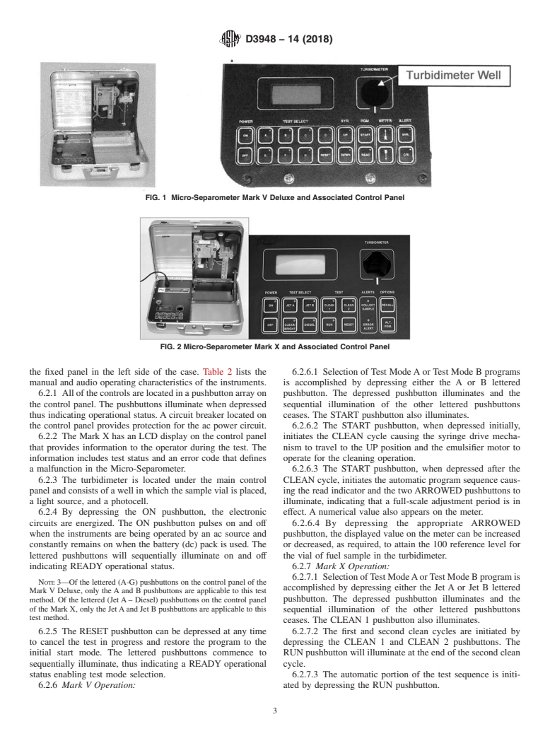
FIG. 1 Micro-Separometer Mark V Deluxe and Associated Control Panel
FIG. 2 Micro-Separometer Mark X and Associated Control Panel
the fixed panel in the left side of the case. Table 2 lists the 6.2.6.1 Selection of Test ModeAor Test Mode B programs
manual and audio operating characteristics of the instruments. is accomplished by depressing either the A or B lettered
6.2.1 Allofthecontrolsarelocatedinapushbuttonarrayon pushbutton. The depressed pushbutton illuminates and the
the control panel. The pushbuttons illuminate when depressed sequential illumination of the other lettered pushbuttons
thus indicating operational status. A circuit breaker located on ceases. The START pushbutton also illuminates.
the control panel provides protection for the ac power circuit. 6.2.6.2 The START pushbutton, when depressed initially,
6.2.2 The Mark X has an LCD display on the control panel initiates the CLEAN cycle causing the syringe drive mecha-
that provides information to the operator during the test. The nism to travel to the UP position and the emulsifier motor to
information includes test status and an error code that defines operate for the cleaning operation.
a malfunction in the Micro-Separometer. 6.2.6.3 The START pushbutton, when depressed after the
6.2.3 The turbidimeter is located under the main control CLEAN cycle, initiates the automatic program sequence caus-
panel and consists of a well in which the sample vial is placed, ing the read indicator and the twoARROWED pushbuttons to
a light source, and a photocell. illuminate, indicating that a full-scale adjustment period is in
6.2.4 By depressing the ON pushbutton, the electronic effect. A numerical value also appears on the meter.
circuits are energized. The ON pushbutton pulses on and off 6.2.6.4 By depressing the appropriate ARROWED
when the instruments are being operated by an ac source and pushbutton, the displayed value on the meter can be increased
constantly remains on when the battery (dc) pack is used. The or decreased, as required, to attain the 100 reference level for
lettered pushbuttons will sequentially illuminate on and off the vial of fuel sample in the turbidimeter.
indicating READY operational status. 6.2.7 Mark X Operation:
6.2.7.1 SelectionofTestModeAorTestModeBprogramis
NOTE 3—Of the lettered (A-G) pushbuttons on the control panel of the
accomplished by depressing either the Jet A or Jet B lettered
Mark V Deluxe, only the A and B pushbuttons are applicable to this test
pushbutton. The depressed pushbutton illuminates and the
method. Of the lettered (Jet A – Diesel) pushbuttons on the control panel
of the Mark X, only the JetAand Jet B pushbuttons are applicable to this
sequential illumination of the other lettered pushbuttons
test method.
ceases. The CLEAN 1 pushbutton also illuminates.
6.2.5 The RESET pushbutton can be depressed at any time 6.2.7.2 The first and second clean cycles are initiated by
to cancel the test in progress and restore the program to the depressing the CLEAN 1 and CLEAN 2 pushbuttons. The
initial start mode. The lettered pushbuttons commence to RUN pushbutton will illuminate at the end of the second clean
sequentially illuminate, thus indicating a READY operational cycle.
status enabling test mode selection. 6.2.7.3 The automatic portion of the test sequence is initi-
6.2.6 Mark V Operation: ated by depressing the RUN pushbutton.
D3948 − 14 (2018)
TABLE 2 Manual and Audio Operating Characteristics of the Various Model 1140 Micro-Separometer Instruments
Available Test Mode(s) Deluxe A and B Mark X
Function
Test Mode Select Pushbutton Pushbutton
Mode A Depress A Depress Jet A
Mode B Depress B Depress Jet B
Syringe Drive Not required Not required
Speed Selection
Clean Cycle START Depress Clean 1
Depress Depress Clean 2
Pushbutton
Automatic Sequence
Initiate START Depress Run
Cancel RESET
1st Meter Read
1st Meter De
...
This document is not an ASTM standard and is intended only to provide the user of an ASTM standard an indication of what changes have been made to the previous version. Because
it may not be technically possible to adequately depict all changes accurately, ASTM recommends that users consult prior editions as appropriate. In all cases only the current version
of the standard as published by ASTM is to be considered the official document.
Designation: D3948 − 14 D3948 − 14 (Reapproved 2018) An American National Standard
Standard Test Method for
Determining Water Separation Characteristics of Aviation
Turbine Fuels by Portable Separometer
This standard is issued under the fixed designation D3948; the number immediately following the designation indicates the year of
original adoption or, in the case of revision, the year of last revision. A number in parentheses indicates the year of last reapproval. A
superscript epsilon (´) indicates an editorial change since the last revision or reapproval.
This standard has been approved for use by agencies of the U.S. Department of Defense.
1. Scope*Scope
1.1 This test method covers a rapid portable means for field and laboratory use to rate the ability of aviation turbine fuels to
release entrained or emulsified water when passed through fiberglass coalescing material.
1.2 The procedure section of this test method contains two different modes of test equipment operation. The primary difference
between the modes of operation is the rate of fuel flow through the fiberglass coalescing material. Test method selection is
dependent on the particular fuel to be tested.
1.3 The values stated in SI units are to be regarded as the standard. The values given in parentheses are for information only.after
SI units are provided for information only and are not considered standard.
1.4 This standard does not purport to address all of the safety concerns, if any, associated with its use. It is the responsibility
of the user of this standard to establish appropriate safety safety, health, and healthenvironmental practices and determine the
applicability of regulatory limitations prior to use.
1.5 This international standard was developed in accordance with internationally recognized principles on standardization
established in the Decision on Principles for the Development of International Standards, Guides and Recommendations issued
by the World Trade Organization Technical Barriers to Trade (TBT) Committee.
2. Referenced Documents
2.1 ASTM Standards:
D1655 Specification for Aviation Turbine Fuels
D2550 Method of Test for Water Separation Characteristics of Aviation Turbine Fuels (Withdrawn 1989)
D3602 Test Method for Water Separation Characteristics of Aviation Turbine Fuels (Withdrawn 1994)
D4306 Practice for Aviation Fuel Sample Containers for Tests Affected by Trace Contamination
D7224 Test Method for Determining Water Separation Characteristics of Kerosine-Type Aviation Turbine Fuels Containing
Additives by Portable Separometer
D7261 Test Method for Determining Water Separation Characteristics of Diesel Fuels by Portable Separometer
2.2 Military Standards:
MIL-T-5624 Turbine Fuel, Aviation Grades JP-4, JP-5, and JP-5/JP-8 ST
MIL-T-38219 Turbine Fuel, Low Volatility, JP-7
MIL-T-83133 Turbine Fuel, Aviation, Kerosene Types, NATO F34 (JP-8), NATO F-35, and JP-8+100
3. Terminology
3.1 For definitions of terms used in this test method that are not shown below, refer to Test Methods D7224 and D7261.
3.2 Definitions:
This test method is under the jurisdiction of ASTM Committee D02 on Petroleum Products, Liquid Fuels, and Lubricants and is the direct responsibility of Subcommittee
D02.J0.05 on Fuel Cleanliness.
Current edition approved Dec. 1, 2014Oct. 1, 2018. Published January 2015November 2018. Originally approved in 1980. Last previous edition approved in 20132014
as D3948 – 13.D3948 – 14. DOI: 10.1520/D3948-14.10.1520/D3948-14R18.
For referenced ASTM standards, visit the ASTM website, www.astm.org, or contact ASTM Customer Service at service@astm.org. For Annual Book of ASTM Standards
volume information, refer to the standard’s Document Summary page on the ASTM website.
The last approved version of this historical standard is referenced on www.astm.org.
Available from Standardization Documents Order Desk, Bldg. 4 Section D, 700 Robbins Ave., Philadelphia, PA 19111-5094, Attn: NPODS.
*A Summary of Changes section appears at the end of this standard
Copyright © ASTM International, 100 Barr Harbor Drive, PO Box C700, West Conshohocken, PA 19428-2959. United States
D3948 − 14 (2018)
5 5
3.2.1 Micro-Separometer rating (MSEP rating), n—in the aviation fuel industry, a numerical value indicating the ease of
separating emulsified water from aviation (jet) fuel by coalescence as affected by the presence of surface active materials (also
known as surface active agents or surfactants).
‘MSEP’, ‘DSEP’, and ‘Micro-Separometer’ are trademarks of EMCEE Electronics, Inc., 520 Cypress Ave., Venice, FL 34285.
3.2.1.1 Discussion—
MSEP ratings obtained using Test A and Test B are termed MSEP-A and MSEP-B, respectively.
3.2.1.2 Discussion—
MSEP ratings are only valid within the range of 50 to 100, with ratings at the upper end of the range indicating a clean fuel with
little or no contamination by surfactants, which is expected to show good water-separating properties when passed through a
filter-separator (coalescing-type filter) in actual service.
3.2.2 reference fluid, n—in MSEP and DSEP [diesel separability] water separability tests, a reference fluid base to which a
prescribed quantity of a known surface active agent has been added.
3.2.2.1 Discussion—
The known surface active agent is typically bis-2-ethylhexyl sodium sulfosuccinate, commonly referred to as AOT, dissolved in
toluene.
3.2.3 surfactant, n—in petroleum fuels, surface active material (or surface active agent) that could disarm (deactivate) filter
separator (coalescing) elements so that free water is not removed from the fuel in actual service.
3.2.3.1 Discussion—
Technically, surfactants affect the interfacial tension between water and fuel which affects the tendency of water to coalesce into
droplets.
3.3 Definitions of Terms Specific to This Standard:
3.3.1 reference fluid base, n—in aviation MSEP water separability tests, jet fuel that has been cleaned in a prescribed manner
to remove all surface-active contaminants (agents), and having a minimum MSEP rating of 97.
4. Summary of Test Method
4.1 A water/fuel sample emulsion is created in a syringe using a high-speed mixer. The emulsion is then expelled from the
syringe at a programmed rate through a standard fiberglass coalescer and the effluent is analyzed for uncoalesced water by a light
transmission measurement. The results are reported on a 0-to-100 scale to the nearest whole number. High ratings indicate the
water is easily coalesced, implying that the fuel is relatively free of surfactant materials. A test can be performed in 5 min to 10
min.
5. Significance and Use
5.1 This test method provides a measure of the presence of surfactants in aviation turbine fuels. Like Test Methods D2550 and
D3602, this test method can detect carryover traces of refinery treating residues in fuel as produced. They can also detect surface
active substances added to or picked up by the fuel during handling from point of production to point of use. Certain additives can
also have an adverse effect on the rating. Some of these substances affect the ability of filter separators to separate free water from
the fuel.
5.2 The Micro-Separometer has a measurement range from 50 to 100. Values obtained outside of those limits are undefined and
invalid. In the event a value greater than 100 is obtained, there is a good probability that light transmittance was reduced by
material contained in the fuel used to set the 100 reference level. The material was subsequently removed during the coalescing
portion of the test, thus, the processed fuel had a higher light transmittance than the fuel sample used to obtain the 100 reference
level resulting in the final rating measuring in excess of 100.
5.3 Test Mode A function of the separometer will give approximately the same rating for Jet A, Jet A-1, MIL JP-5, MIL JP-7,
and MIL JP-8 fuels as Test Methods D2550 and D3602. Using Mode A water separation characteristic ratings of Jet B and MIL
JP-4 fuels will not necessarily be equivalent to Test Method D2550 but will give approximately the same rating as Test Method
D3602. All Micro-Separometers have Test Mode A capability.
D3948 − 14 (2018)
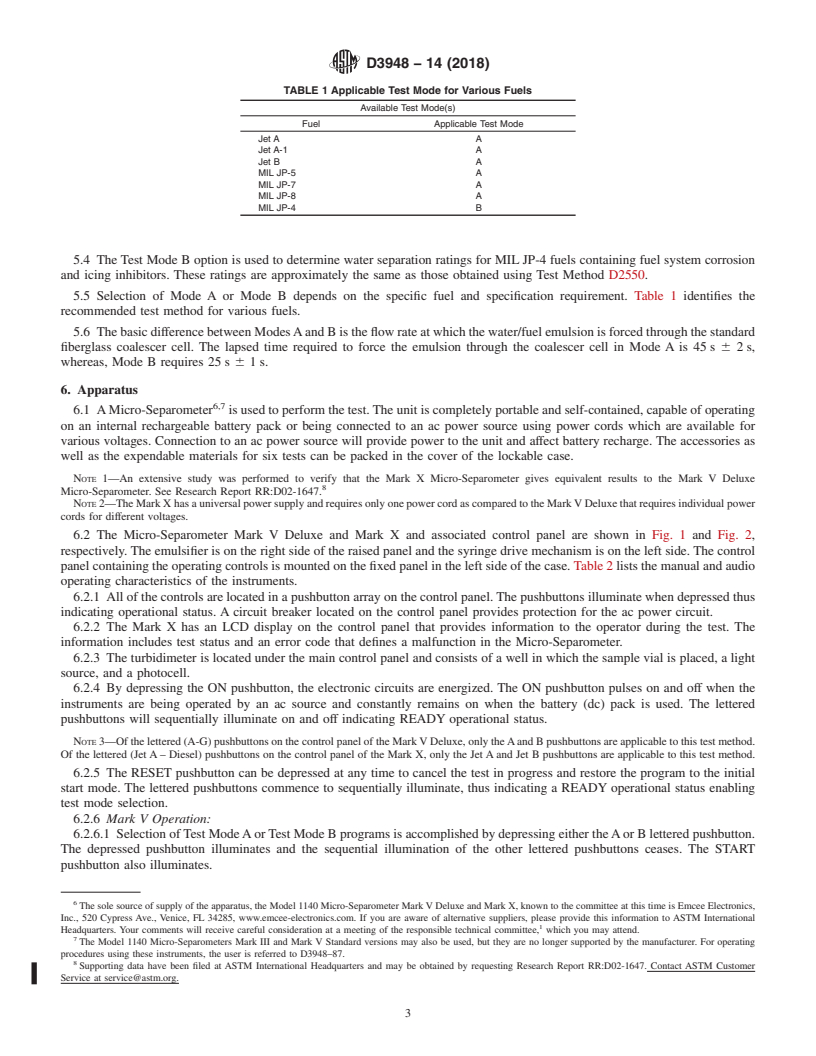
TABLE 1 Applicable Test Mode for Various Fuels
Available Test Mode(s)
Fuel Applicable Test Mode
Jet A A
Jet A-1 A
Jet B A
MIL JP-5 A
MIL JP-7 A
MIL JP-8 A
MIL JP-4 B
5.4 The Test Mode B option is used to determine water separation ratings for MIL JP-4 fuels containing fuel system corrosion
and icing inhibitors. These ratings are approximately the same as those obtained using Test Method D2550.
5.5 Selection of Mode A or Mode B depends on the specific fuel and specification requirement. Table 1 identifies the
recommended test method for various fuels.
5.6 The basic difference between Modes A and B is the flow rate at which the water/fuel emulsion is forced through the standard
fiberglass coalescer cell. The lapsed time required to force the emulsion through the coalescer cell in Mode A is 45 s 6 2 s,
whereas, Mode B requires 25 s 6 1 s.
6. Apparatus
6,7
6.1 A Micro-Separometer is used to perform the test. The unit is completely portable and self-contained, capable of operating
on an internal rechargeable battery pack or being connected to an ac power source using power cords which are available for
various voltages. Connection to an ac power source will provide power to the unit and affect battery recharge. The accessories as
well as the expendable materials for six tests can be packed in the cover of the lockable case.
NOTE 1—An extensive study was performed to verify that the Mark X Micro-Separometer gives equivalent results to the Mark V Deluxe
Micro-Separometer. See Research Report RR:D02-1647.
NOTE 2—The Mark X has a universal power supply and requires only one power cord as compared to the Mark V Deluxe that requires individual power
cords for different voltages.
6.2 The Micro-Separometer Mark V Deluxe and Mark X and associated control panel are shown in Fig. 1 and Fig. 2,
respectively. The emulsifier is on the right side of the raised panel and the syringe drive mechanism is on the left side. The control
panel containing the operating controls is mounted on the fixed panel in the left side of the case. Table 2 lists the manual and audio
operating characteristics of the instruments.
6.2.1 All of the controls are located in a pushbutton array on the control panel. The pushbuttons illuminate when depressed thus
indicating operational status. A circuit breaker located on the control panel provides protection for the ac power circuit.
6.2.2 The Mark X has an LCD display on the control panel that provides information to the operator during the test. The
information includes test status and an error code that defines a malfunction in the Micro-Separometer.
6.2.3 The turbidimeter is located under the main control panel and consists of a well in which the sample vial is placed, a light
source, and a photocell.
6.2.4 By depressing the ON pushbutton, the electronic circuits are energized. The ON pushbutton pulses on and off when the
instruments are being operated by an ac source and constantly remains on when the battery (dc) pack is used. The lettered
pushbuttons will sequentially illuminate on and off indicating READY operational status.
NOTE 3—Of the lettered (A-G) pushbuttons on the control panel of the Mark V Deluxe, only the A and B pushbuttons are applicable to this test method.
Of the lettered (Jet A – Diesel) pushbuttons on the control panel of the Mark X, only the Jet A and Jet B pushbuttons are applicable to this test method.
6.2.5 The RESET pushbutton can be depressed at any time to cancel the test in progress and restore the program to the initial
start mode. The lettered pushbuttons commence to sequentially illuminate, thus indicating a READY operational status enabling
test mode selection.
6.2.6 Mark V Operation:
6.2.6.1 Selection of Test Mode A or Test Mode B programs is accomplished by depressing either the A or B lettered pushbutton.
The depressed pushbutton illuminates and the sequential illumination of the other lettered pushbuttons ceases. The START
pushbutton also illuminates.
The sole source of supply of the apparatus, the Model 1140 Micro-Separometer Mark V Deluxe and Mark X, known to the committee at this time is Emcee Electronics,
Inc., 520 Cypress Ave., Venice, FL 34285, www.emcee-electronics.com. If you are aware of alternative suppliers, please provide this information to ASTM International
Headquarters. Your comments will receive careful consideration at a meeting of the responsible technical committee, which you may attend.
The Model 1140 Micro-Separometers Mark III and Mark V Standard versions may also be used, but they are no longer supported by the manufacturer. For operating
procedures using these instruments, the user is referred to D3948–87.
Supporting data have been filed at ASTM International Headquarters and may be obtained by requesting Research Report RR:D02-1647. Contact ASTM Customer
Service at service@astm.org.
D3948 − 14 (2018)
FIG. 1 Micro-Separometer Mark V Deluxe and Associated Control Panel
FIG. 2 Micro-Separometer Mark X and Associated Control Panel
6.2.6.2 The START pushbutton, when depressed initially, initiates the CLEAN cycle causing the syringe drive mechanism to
travel to the UP position and the emulsifier motor to operate for the cleaning operation.
6.2.6.3 The START pushbutton, when depressed after the CLEAN cycle, initiates the automatic program sequence causing the
read indicator and the two ARROWED pushbuttons to illuminate, indicating that a full-scale adjustment period is in effect. A
numerical value also appears on the meter.
6.2.6.4 By depressing the appropriate ARROWED pushbutton, the displayed value on the meter can be increased or decreased,
as required, to attain the 100 reference level for the vial of fuel sample in the turbidimeter.
6.2.7 Mark X Operation:
6.2.7.1 Selection of Test Mode A or Test Mode B program is accomplished by depressing either the Jet A or Jet B lettered
pushbutton. The depressed pushbutton illuminates and the sequential illumination of the other lettered pushbuttons ceases. The
CLEAN 1 pushbutton also illuminates.
6.2.7.2 The first and second clean cycles are initiated by depressing the CLEAN 1 and CLEAN 2 pushbuttons. The RUN
pushbutton will illuminate at the end of the second clean cycle.
6.2.7.3 The automatic portion of the
...
Questions, Comments and Discussion
Ask us and Technical Secretary will try to provide an answer. You can facilitate discussion about the standard in here.