


ETSI TS 138 215 V19.2.0 (2026-02)
5G; NR; Physical layer measurements (3GPP TS 38.215 version 19.2.0 Release 19)
5G; NR; Physical layer measurements (3GPP TS 38.215 version 19.2.0 Release 19)
RTS/TSGR-0138215vj20
General Information
- Status
- Not Published
- Technical Committee
- 3GPP RAN 1 - Radio layer 1 specification
- Current Stage
- 12 - Citation in the OJ (auto-insert)
- Completion Date
- 16-Feb-2026
Frequently Asked Questions
ETSI TS 138 215 V19.2.0 (2026-02) is a standard published by the European Telecommunications Standards Institute (ETSI). Its full title is "5G; NR; Physical layer measurements (3GPP TS 38.215 version 19.2.0 Release 19)". This standard covers: RTS/TSGR-0138215vj20
RTS/TSGR-0138215vj20
ETSI TS 138 215 V19.2.0 (2026-02) is available in PDF format for immediate download after purchase. The document can be added to your cart and obtained through the secure checkout process. Digital delivery ensures instant access to the complete standard document.
Standards Content (Sample)
TECHNICAL SPECIFICATION
5G;
NR;
Physical layer measurements
(3GPP TS 38.215 version 19.2.0 Release 19)
3GPP TS 38.215 version 19.2.0 Release 19 1 ETSI TS 138 215 V19.2.0 (2026-02)
Reference
RTS/TSGR-0138215vj20
Keywords
5G
ETSI
650 Route des Lucioles
F-06921 Sophia Antipolis Cedex - FRANCE
Tel.: +33 4 92 94 42 00 Fax: +33 4 93 65 47 16
Siret N° 348 623 562 00017 - APE 7112B
Association à but non lucratif enregistrée à la
Sous-Préfecture de Grasse (06) N° w061004871
Important notice
The present document can be downloaded from the
ETSI Search & Browse Standards application.
The present document may be made available in electronic versions and/or in print. The content of any electronic and/or
print versions of the present document shall not be modified without the prior written authorization of ETSI. In case of any
existing or perceived difference in contents between such versions and/or in print, the prevailing version of an ETSI
deliverable is the one made publicly available in PDF format on ETSI deliver repository.
Users should be aware that the present document may be revised or have its status changed,
this information is available in the Milestones listing.
If you find errors in the present document, please send your comments to
the relevant service listed under Committee Support Staff.
If you find a security vulnerability in the present document, please report it through our
Coordinated Vulnerability Disclosure (CVD) program.
Notice of disclaimer & limitation of liability
The information provided in the present deliverable is directed solely to professionals who have the appropriate degree of
experience to understand and interpret its content in accordance with generally accepted engineering or
other professional standard and applicable regulations.
No recommendation as to products and services or vendors is made or should be implied.
No representation or warranty is made that this deliverable is technically accurate or sufficient or conforms to any law
and/or governmental rule and/or regulation and further, no representation or warranty is made of merchantability or fitness
for any particular purpose or against infringement of intellectual property rights.
In no event shall ETSI be held liable for loss of profits or any other incidental or consequential damages.
Any software contained in this deliverable is provided "AS IS" with no warranties, express or implied, including but not
limited to, the warranties of merchantability, fitness for a particular purpose and non-infringement of intellectual property
rights and ETSI shall not be held liable in any event for any damages whatsoever (including, without limitation, damages
for loss of profits, business interruption, loss of information, or any other pecuniary loss) arising out of or related to the use
of or inability to use the software.
Copyright Notification
No part may be reproduced or utilized in any form or by any means, electronic or mechanical, including photocopying and
microfilm except as authorized by written permission of ETSI.
The content of the PDF version shall not be modified without the written authorization of ETSI.
The copyright and the foregoing restriction extend to reproduction in all media.
© ETSI 2026.
All rights reserved.
ETSI
3GPP TS 38.215 version 19.2.0 Release 19 2 ETSI TS 138 215 V19.2.0 (2026-02)
Intellectual Property Rights
Essential patents
IPRs essential or potentially essential to normative deliverables may have been declared to ETSI. The declarations
pertaining to these essential IPRs, if any, are publicly available for ETSI members and non-members, and can be
found in ETSI SR 000 314: "Intellectual Property Rights (IPRs); Essential, or potentially Essential, IPRs notified to
ETSI in respect of ETSI standards", which is available from the ETSI Secretariat. Latest updates are available on the
ETSI IPR online database.
Pursuant to the ETSI Directives including the ETSI IPR Policy, no investigation regarding the essentiality of IPRs,
including IPR searches, has been carried out by ETSI. No guarantee can be given as to the existence of other IPRs not
referenced in ETSI SR 000 314 (or the updates on the ETSI Web server) which are, or may be, or may become,
essential to the present document.
Trademarks
The present document may include trademarks and/or tradenames which are asserted and/or registered by their owners.
ETSI claims no ownership of these except for any which are indicated as being the property of ETSI, and conveys no
right to use or reproduce any trademark and/or tradename. Mention of those trademarks in the present document does
not constitute an endorsement by ETSI of products, services or organizations associated with those trademarks.
DECT™, PLUGTESTS™, UMTS™ and the ETSI logo are trademarks of ETSI registered for the benefit of its
Members. 3GPP™, LTE™ and 5G™ logo are trademarks of ETSI registered for the benefit of its Members and of the
3GPP Organizational Partners. oneM2M™ logo is a trademark of ETSI registered for the benefit of its Members and of ®
the oneM2M Partners. GSM and the GSM logo are trademarks registered and owned by the GSM Association.
Legal Notice
This Technical Specification (TS) has been produced by ETSI 3rd Generation Partnership Project (3GPP).
The present document may refer to technical specifications or reports using their 3GPP identities. These shall be
interpreted as being references to the corresponding ETSI deliverables.
The cross reference between 3GPP and ETSI identities can be found at 3GPP to ETSI numbering cross-referencing.
Modal verbs terminology
In the present document "shall", "shall not", "should", "should not", "may", "need not", "will", "will not", "can" and
"cannot" are to be interpreted as described in clause 3.2 of the ETSI Drafting Rules (Verbal forms for the expression of
provisions).
"must" and "must not" are NOT allowed in ETSI deliverables except when used in direct citation.
ETSI
3GPP TS 38.215 version 19.2.0 Release 19 3 ETSI TS 138 215 V19.2.0 (2026-02)
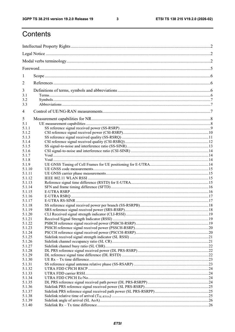
Contents
Intellectual Property Rights . 2
Legal Notice . 2
Modal verbs terminology . 2
Foreword . 5
1 Scope . 6
2 References . 6
3 Definitions of terms, symbols and abbreviations . 6
3.1 Terms . 6
3.2 Symbols . 7
3.3 Abbreviations . 7
4 Control of UE/NG-RAN measurements . 7
5 Measurement capabilities for NR . 8
5.1 UE measurement capabilities . 8
5.1.1 SS reference signal received power (SS-RSRP) . 9
5.1.2 CSI reference signal received power (CSI-RSRP) . 10
5.1.3 SS reference signal received quality (SS-RSRQ) . 11
5.1.4 CSI reference signal received quality (CSI-RSRQ) . 12
5.1.5 SS signal-to-noise and interference ratio (SS-SINR) . 13
5.1.6 CSI signal-to-noise and interference ratio (CSI-SINR) . 14
5.1.7 Void . 14
5.1.8 Void . 14
5.1.9 UE GNSS Timing of Cell Frames for UE positioning for E-UTRA. 14
5.1.10 UE GNSS code measurements. 15
5.1.11 UE GNSS carrier phase measurements . 15
5.1.12 IEEE 802.11 WLAN RSSI . 15
5.1.13 Reference signal time difference (RSTD) for E-UTRA. 15
5.1.14 SFN and frame timing difference (SFTD) . 16
5.1.15 E-UTRA RSRP . 16
5.1.16 E-UTRA RSRQ . 17
5.1.17 E-UTRA RS-SINR . 17
5.1.18 SS reference signal received power per branch (SS-RSRPB) . 18
5.1.19 SRS reference signal received power (SRS-RSRP) . 18
5.1.20 CLI Received signal strength indicator (CLI-RSSI) . 19
5.1.21 Received Signal Strength Indicator (RSSI) . 19
5.1.22 PSBCH reference signal received power (PSBCH-RSRP) . 19
5.1.23 PSSCH reference signal received power (PSSCH-RSRP) . 20
5.1.24 PSСCH reference signal received power (PSCCH-RSRP) . 20
5.1.25 Sidelink received signal strength indicator (SL RSSI) . 21
5.1.26 Sidelink channel occupancy ratio (SL CR) . 21
5.1.27 Sidelink channel busy ratio (SL CBR) . 22
5.1.28 DL PRS reference signal received power (DL PRS-RSRP) . 22
5.1.29 DL reference signal time difference (DL RSTD) . 22
5.1.30 UE Rx – Tx time difference . 23
5.1.31 SS reference signal antenna relative phase (SS-RSARP) . 23
5.1.32 UTRA FDD CPICH RSCP . 24
5.1.33 UTRA FDD carrier RSSI . 24
5.1.34 UTRA FDD CPICH Ec/No . 24
5.1.35 DL PRS reference signal received path power (DL PRS-RSRPP) . 24
5.1.36 Sidelink PRS reference signal received power (SL PRS-RSRP) . 25
5.1.37 Sidelink PRS reference signal received path power (SL PRS-RSRPP) . 25
5.1.38 Sidelink relative time of arrival (T ) . 25
SL-RTOA
5.1.39 Sidelink angle of arrival (SL AoA) . 26
5.1.40 Sidelink Rx – Tx time difference . 26
ETSI
3GPP TS 38.215 version 19.2.0 Release 19 4 ETSI TS 138 215 V19.2.0 (2026-02)
5.1.41 Sidelink reference signal time difference (SL RSTD) . 26
5.1.42 DL reference signal carrier phase (DL RSCP) . 27
5.1.43 DL reference signal carrier phase difference (DL RSCPD) . 27
5.1.44 Sidelink PRS received signal strength indicator (SL PRS-RSSI) . 27
5.1.45 Time domain channel property (TDCP) . 28
5.1.46 UE Rx – Tx time difference subframe offset . 28
5.1.47 DL timing drift . 28
5.1.48 Sidelink PRS channel occupancy ratio (SL PRS-CR) . 28
5.1.49 Sidelink PRS channel busy ratio (SL PRS-CBR) . 29
5.1.50 Coherent joint transmission calibration delay offset . 29
5.1.51 Coherent joint transmission calibration frequency offset . 30
5.1.52 Coherent joint transmission calibration phase offset . 30
5.1.53 Low power reference signal received power (LP-RSRP) . 30
5.1.54 Low power reference signal received quality (LP-RSRQ) . 31
5.1.55 Squared Generalized Cosine Similarity (SGCS). 31
5.2 NG-RAN measurement abilities . 31
5.2.1 SSS transmit power . 32
5.2.2 UL Relative Time of Arrival (T ) . 32
UL-RTOA
5.2.3 gNB Rx – Tx time difference. 32
5.2.4 UL Angle of Arrival (UL AoA) . 33
5.2.5 UL SRS reference signal received power (UL SRS-RSRP) . 33
5.2.6 UL SRS reference signal received path power (UL SRS-RSRPP) . 34
5.2.7 Timing advance (T ) . 34
ADV
5.2.8 UL reference signal carrier phase (UL RSCP) . 35
5.2.9 UL SRS time domain channel timing (UL SRS-TDCT) . 35
5.2.10 UL SRS time domain channel power (UL SRS-TDCP) . 36
Annex A (informative): Change history . 37
History . 41
ETSI
3GPP TS 38.215 version 19.2.0 Release 19 5 ETSI TS 138 215 V19.2.0 (2026-02)
Foreword
rd
This Technical Specification has been produced by the 3 Generation Partnership Project (3GPP).
The contents of the present document are subject to continuing work within the TSG and may change following formal
TSG approval. Should the TSG modify the contents of the present document, it will be re-released by the TSG with an
identifying change of release date and an increase in version number as follows:
Version x.y.z
where:
x the first digit:
1 presented to TSG for information;
2 presented to TSG for approval;
3 or greater indicates TSG approved document under change control.
y the second digit is incremented for all changes of substance, i.e. technical enhancements, corrections,
updates, etc.
z the third digit is incremented when editorial only changes have been incorporated in the document.
ETSI
3GPP TS 38.215 version 19.2.0 Release 19 6 ETSI TS 138 215 V19.2.0 (2026-02)
1 Scope
The present document describes the physical layer measurements for NR.
2 References
The following documents contain provisions which, through reference in this text, constitute provisions of the present
document.
[1] 3GPP TR 21.905: "Vocabulary for 3GPP Specifications"
[2] 3GPP TS 38.201: "NR; Physical Layer – General Description"
[3] 3GPP TS 38.211: "NR; Physical channels and modulation"
[4] 3GPP TS 38.212: "NR; Multiplexing and channel coding"
[5] 3GPP TS 38.213: "NR; Physical layer procedures for control channels"
[6] 3GPP TS 38.214: "NR; Physical layer procedures for data channels"
[7] 3GPP TS 38.321: "NR; Medium Access Control (MAC) protocol specification"
[8] 3GPP TS 38.331: "NR; Radio Resource Control (RRC); Protocol specification"
[9] 3GPP TS 38.104: "NR; Base Station (BS) radio transmission and reception"
[10] 3GPP TS 36.331: "Evolved Universal Terrestrial Radio Access (E-UTRA); Radio Resource
Control (RRC); Protocol specification"
[11] IEEE 802.11, Part 11: "Wireless LAN Medium Access Control (MAC) and Physical Layer (PHY)
specifications, IEEE Std."
[12] 3GPP TS 38.133: "NR; Requirements for support of radio resource management"
[13] 3GPP TS 36.211: "Evolved Universal Terrestrial Radio Access (E-UTRA); Physical channels and
modulation"
[14] 3GPP TS 38.509: "5GS; Special conformance testing functions for User Equipment (UE)"
[15] 3GPP TS 38.901: "Study on channel model for frequencies from 0.5 to 100 GHz"
[16] 3GPP TS 38.455: "NR Positioning Protocol A (NRPPa)"
[17] 3GPP TS 37.213: "Physical layer procedures for shared spectrum channel access"
[18] 3GPP TS 38.305: "NG Radio Access Network (NG-RAN); Stage 2 functional specification of
User Equipment (UE) positioning in NG-RAN"
[19] 3GPP TS 38.108: "Satellite Access Node radio transmission and reception"
3 Definitions of terms, symbols and abbreviations
3.1 Terms
For the purposes of the present document, the terms and definitions given in TR 21.905 [1] and the following apply. A
term defined in the present document takes precedence over the definition of the same term, if any, in TR 21.905 [1].
ETSI
3GPP TS 38.215 version 19.2.0 Release 19 7 ETSI TS 138 215 V19.2.0 (2026-02)
3.2 Symbols
For the purposes of the present document, the following symbols apply:
3.3 Abbreviations
For the purposes of the present document, the abbreviations given in TR 21.905 [1] and the following apply. An
abbreviation defined in the present document takes precedence over the definition of the same abbreviation, if any, in
TR 21.905 [1].
ARFCN Absolute Radio-Frequency Channel Number
CLI Cross Link Interference
CSI-RSRP CSI Reference Signal Received Power
CSI-RSRQ CSI Reference Signal Received Quality
E-UTRAN Evolved UTRAN
GNSS Global Navigation Satellite System
GSM Global System for Mobile communication
LBT Listen Before Talk
SRS Sounding Reference Signal
SS-RSRP Synchronization Signal Reference Signal Received Power
SS-RSRQ Synchronization Signal Reference Signal Received Quality
UTRAN Universal Terrestrial Radio Access Network
4 Control of UE/NG-RAN measurements
In this clause the general measurement control concept of the higher layers is briefly described to provide an
understanding on how L1 measurements are initiated and controlled by higher layers.
With the measurement specifications L1 provides measurement capabilities for the UE and NG-RAN. These
measurements can be classified in different reported measurement types: intra-frequency, inter-frequency, inter-system,
traffic volume, quality and UE internal measurements.
In the L1 measurement definitions, see clause 5, the measurements are categorised as measurements in the UE or
measurements in the NG-RAN.
ETSI
3GPP TS 38.215 version 19.2.0 Release 19 8 ETSI TS 138 215 V19.2.0 (2026-02)
5 Measurement capabilities for NR
5.1 UE measurement capabilities
The structure of the table defining a UE measurement quantity is shown below.
Column field Comment
Definition
Contains the definition of the measurement.
Applicable for
States in which state(s) it shall be possible to perform this measurement. The following terms are
used in the tables:
RRC_IDLE;
RRC_INACTIVE;
RRC_CONNECTED;
Intra-frequency appended to the RRC state:
Shall be possible to perform in the corresponding RRC state on an intra-frequency cell;
Inter-frequency appended to the RRC state:
Shall be possible to perform in the corresponding RRC state on an inter-frequency cell
Inter-RAT appended to the RRC state:
Shall be possible to perform in the corresponding RRC state on an inter-RAT cell.
If sidelink: it shall be possible to perform this measurement on sidelink.
ETSI
3GPP TS 38.215 version 19.2.0 Release 19 9 ETSI TS 138 215 V19.2.0 (2026-02)
5.1.1 SS reference signal received power (SS-RSRP)
Definition SS reference signal received power (SS-RSRP) is defined as the linear average over the power
contributions (in [W]) of the resource elements that carry secondary synchronization signals. The
measurement time resource(s) for SS-RSRP are confined within SS/PBCH Block Measurement
Time Configuration (SMTC) window duration, except when measurement is being performed by
wake-up receiver (WUR). If SS-RSRP is used for L1-RSRP as configured by reporting
configurations as defined in TS 38.214 [6], the measurement time resources(s) restriction by
SMTC window duration is not applicable.
For SS-RSRP determination demodulation reference signals for physical broadcast channel
(PBCH) and, if indicated by higher layers, CSI reference signals in addition to secondary
synchronization signals may be used. SS-RSRP using demodulation reference signal for PBCH
or CSI reference signal shall be measured by linear averaging over the power contributions of
the resource elements that carry corresponding reference signals taking into account power
scaling for the reference signals as defined in TS 38.213 [5]. If SS-RSRP is not used for L1-
RSRP, the additional use of CSI reference signals for SS-RSRP determination is not applicable.
SS-RSRP shall be measured only among the reference signals corresponding to SS/PBCH
blocks with the same SS/PBCH block index and the same physical-layer cell identity.
If SS-RSRP is not used for L1-RSRP and higher-layers indicate certain SS/PBCH blocks for
performing SS-RSRP measurements, then SS-RSRP is measured only from the indicated set of
SS/PBCH block(s).
For frequency range 1, the reference point for the SS-RSRP shall be the antenna connector of
the UE. For frequency range 2, SS-RSRP shall be measured based on the combined signal from
antenna elements corresponding to a given receiver branch. For frequency range 1 and 2, if
receiver diversity is in use by the UE, the reported SS-RSRP value shall not be lower than the
corresponding SS-RSRP of any of the individual receiver branches.
Applicable for If SS-RSRP is used for L1-RSRP or predicted RSRP,
RRC_CONNECTED intra-frequency.
If SS-RSRP is being performed by wake-up receiver (WUR),
RRC_IDLE for serving cell,
RRC_INACTIVE for serving cell.
Otherwise,
RRC_IDLE intra-frequency,
RRC_IDLE inter-frequency,
RRC_INACTIVE intra-frequency,
RRC_INACTIVE inter-frequency,
RRC_CONNECTED intra-frequency,
RRC_CONNECTED inter-frequency
NOTE 1: The number of resource elements within the measurement period that are used by the UE to determine
SS-RSRP is left up to the UE implementation with the limitation that corresponding measurement
accuracy requirements have to be fulfilled.
NOTE 2: The power per resource element is determined from the energy received during the useful part of the
symbol, excluding the CP.
ETSI
3GPP TS 38.215 version 19.2.0 Release 19 10 ETSI TS 138 215 V19.2.0 (2026-02)
5.1.2 CSI reference signal received power (CSI-RSRP)
Definition CSI reference signal received power (CSI-RSRP), is defined as the linear average over the
power contributions (in [W]) of the resource elements of the antenna port(s) that carry CSI
reference signals configured for RSRP measurements within the considered measurement
frequency bandwidth in the configured CSI-RS occasions.
For CSI-RSRP determination CSI reference signals transmitted on antenna port 3000 according
to TS 38.211 [3] shall be used. If CSI-RSRP is used for L1-RSRP, CSI reference signals
transmitted on antenna ports 3000, 3001 can be used for CSI-RSRP determination.
For intra-frequency CSI-RSRP measurements, if the measurement gap is not configured, UE is
not expected to measure the CSI-RS resource(s) outside of the active downlink bandwidth part.
For frequency range 1, the reference point for the CSI-RSRP shall be the antenna connector of
the UE. For frequency range 2, CSI-RSRP shall be measured based on the combined signal
from antenna elements corresponding to a given receiver branch. For frequency range 1 and 2, if
receiver diversity is in use by the UE, the reported CSI-RSRP value shall not be lower than the
corresponding CSI-RSRP of any of the individual receiver branches.
Applicable for If CSI-RSRP is used for L1-RSRP or predicted RSRP,
RRC_CONNECTED intra-frequency.
Otherwise,
RRC_CONNECTED intra-frequency,
RRC_CONNECTED inter-frequency
NOTE 1: The number of resource elements within the considered measurement frequency bandwidth and within the
measurement period that are used by the UE to determine CSI-RSRP is left up to the UE implementation
with the limitation that corresponding measurement accuracy requirements have to be fulfilled.
NOTE 2: The power per resource element is determined from the energy received during the useful part of the
symbol, excluding the CP.
ETSI
3GPP TS 38.215 version 19.2.0 Release 19 11 ETSI TS 138 215 V19.2.0 (2026-02)
5.1.3 SS reference signal received quality (SS-RSRQ)
Definition Secondary synchronization signal reference signal received quality (SS-RSRQ) is defined as the
ratio of N×SS-RSRP / NR carrier RSSI, where N is the number of resource blocks in the NR
carrier RSSI measurement bandwidth. The measurements in the numerator and denominator
shall be made over the same set of resource blocks.
NR carrier Received Signal Strength Indicator (NR carrier RSSI), comprises the linear average of
the total received power (in [W]) observed only in certain OFDM symbols of measurement time
resource(s), in the measurement bandwidth, over N number of resource blocks from all sources,
including co-channel serving and non-serving cells, adjacent channel interference, thermal noise
etc. For cell selection, according to Clause 4.1 of TS 38.133 [12], the measurement time
resources(s) for NR Carrier RSSI are not constrained. Otherwise, the measurement time
resource(s) for NR Carrier RSSI are confined within SS/PBCH Block Measurement Time
Configuration (SMTC) window duration, except when measurement is being performed by wake-
up receiver (WUR).
If indicated by higher-layers, if measurement gap is not used, the NR Carrier RSSI is measured
in slots within the SMTC window duration that are indicated by the higher layer parameter
measurementSlots and in OFDM symbols given by Table 5.1.3-1 and, if measurement gap is
used, the NR Carrier RSSI is measured in slots within the SMTC window duration that are
indicated by the higher layer parameter measurementSlots and in OFDM symbols given by Table
5.1.3-1 that are overlapped with the measurement gap, which is defined in TS38.133 [12].
- For intra-frequency measurements, NR Carrier RSSI is measured with timing reference
corresponding to the serving cell in the frequency layer
- For inter-frequency measurements, NR Carrier RSSI is measured with timing reference
corresponding to any cell in the target frequency layer
Otherwise not indicated by higher-layers, if measurement gap is not used, NR Carrier RSSI is
measured from OFDM symbols within SMTC window duration and, if measurement gap is used,
NR Carrier RSSI is measured from OFDM symbols corresponding to overlapped time span
between SMTC window duration and the measurement gap.
If higher-layers indicate certain SS/PBCH blocks for performing SS-RSRQ measurements, then
SS-RSRP is measured only from the indicated set of SS/PBCH block(s).
For frequency range 1, the reference point for the SS-RSRQ shall be the antenna connector of
the UE. For frequency range 2, NR Carrier RSSI shall be measured based on the combined
signal from antenna elements corresponding to a given receiver branch, where the combining for
NR Carrier RSSI shall be the same as the one used for SS-RSRP measurements. For frequency
range 1 and 2, if receiver diversity is in use by the UE, the reported SS-RSRQ value shall not be
lower than the corresponding SS-RSRQ of any of the individual receiver branches.
Applicable for If SS-RSRQ is being performed by wake-up receiver (WUR),
RRC_IDLE for serving cell,
RRC_INACTIVE for serving cell.
Otherwise,
RRC_IDLE intra-frequency,
RRC_IDLE inter-frequency,
RRC_INACTIVE intra-frequency,
RRC_INACTIVE inter-frequency,
RRC_CONNECTED intra-frequency,
RRC_CONNECTED inter-frequency
Table 5.1.3-1: NR Carrier RSSI measurement symbols
OFDM signal indication endSymbol Symbol indexes
0 {0,1}
1 For 480 kHz and 960 kHz
{0,1,2,.,11,12}; otherwise
{0,1,2,.,10,11}
2 {0,1,2,…, 5}
3 {0,1,2,…, 7}
ETSI
3GPP TS 38.215 version 19.2.0 Release 19 12 ETSI TS 138 215 V19.2.0 (2026-02)
5.1.4 CSI reference signal received quality (CSI-RSRQ)
Definition CSI reference signal received quality (CSI-RSRQ) is defined as the ratio of N×CSI-RSRP to CSI-
RSSI, where N is the number of resource blocks in the CSI-RSSI measurement bandwidth. The
measurements in the numerator and denominator shall be made over the same set of resource
blocks.
CSI Received Signal Strength Indicator (CSI-RSSI), comprises the linear average of the total
received power (in [W]) observed only in OFDM symbols of measurement time resource(s), in
the measurement bandwidth, over N number of resource blocks from all sources, including co-
channel serving and non-serving cells, adjacent channel interference, thermal noise etc. The
measurement time resource(s) for CSI-RSSI corresponds to OFDM symbols containing
configured CSI-RS occasions.
For CSI-RSRQ determination CSI reference signals transmitted on antenna port 3000 according
to TS 38.211 [3] shall be used.
For intra-frequency CSI-RSRQ measurements, if the measurement gap is not configured, UE is
not expected to measure the CSI-RS resource(s) outside of the active downlink bandwidth part.
For frequency range 1, the reference point for the CSI-RSRQ shall be the antenna connector of
the UE. For frequency range 2, CSI-RSSI shall be measured based on the combined signal from
antenna elements corresponding to a given receiver branch, where the combining for CSI-RSSI
shall be the same as the one used for CSI-RSRP measurements. For frequency range 1 and 2, if
receiver diversity is in use by the UE, the reported CSI-RSRQ value shall not be lower than the
corresponding CSI-RSRQ of any of the individual receiver branches.
Applicable for RRC_CONNECTED intra-frequency,
RRC_CONNECTED inter-frequency
ETSI
3GPP TS 38.215 version 19.2.0 Release 19 13 ETSI TS 138 215 V19.2.0 (2026-02)
5.1.5 SS signal-to-noise and interference ratio (SS-SINR)
Definition SS signal-to-noise and interference ratio (SS-SINR), is defined as the linear average over the
power contribution (in [W]) of the resource elements carrying secondary synchronisation signals
divided by the linear average of the noise and interference power contribution (in [W]). If SS-
SINR is used for L1-SINR reporting with dedicated interference measurement resources, the
interference and noise is measured over resource(s) indicated by higher layers as described in
TS 38.214 [6]. Otherwise, the interference and noise are measured over the resource elements
carrying secondary synchronisation signals within the same frequency bandwidth. The
measurement time resource(s) for SS-SINR are confined within SS/PBCH Block Measurement
Time Configuration (SMTC) window duration. If SS-SINR is used for L1-SINR as configured by
reporting configurations defined in TS 38.214 [6], the measurement time resources(s) restriction
by SMTC window duration is not applicable.
For SS-SINR determination demodulation reference signals for physical broadcast channel
(PBCH) in addition to secondary synchronization signals may be used.
If SS-SINR is not used for L1-SINR and higher-layers indicate certain SS/PBCH blocks for
performing SS-SINR measurements, then SS-SINR is measured only from the indicated set of
SS/PBCH block(s).
SINR shall be the antenna connector of the
For frequency range 1, the reference point for the SS-
UE. For frequency range 2, SS-SINR shall be measured based on the combined signal from
antenna elements corresponding to a given receiver branch. For frequency range 1 and 2, if
receiver diversity is in use by the UE, the reported SS-SINR value shall not be lower than the
corresponding SS-SINR of any of the individual receiver branches.
Applicable for If SS-SINR is used for L1-SINR,
RRC_CONNECTED intra-frequency.
Otherwise,
RRC_CONNECTED intra-frequency,
RRC_CONNECTED inter-frequency
ETSI
3GPP TS 38.215 version 19.2.0 Release 19 14 ETSI TS 138 215 V19.2.0 (2026-02)
5.1.6 CSI signal-to-noise and interference ratio (CSI-SINR)
Definition CSI signal-to-noise and interference ratio (CSI-SINR), is defined as the linear average over the
power contribution (in [W]) of the resource elements carrying CSI reference signals divided by
the linear average of the noise and interference power contribution (in [W]). If CSI-SINR is used
for L1-SINR reporting with dedicated interference measurement resources, the interference and
noise is measured over resource(s) indicated by higher layers as described in TS 38.214 [6].
Otherwise, the interference and noise are measured over the resource elements carrying CSI
reference signals within the same frequency bandwidth.
For CSI-SINR determination CSI reference signals transmitted on antenna port 3000 according
to TS 38.211 [3] shall be used. If CSI-SINR is used for L1-SINR, CSI reference signals
transmitted on antenna ports 3000, 3001 can be used for CSI-SINR determination.
For intra-frequency CSI-SINR measurements not used for L1-SINR reporting, if the
measurement gap is not configured, UE is not expected to measure the CSI-RS resource(s)
outside of the active downlink bandwidth part.
For frequency range 1, the reference point for the CSI-SINR shall be the antenna connector of
the UE. For frequency range 2, CSI-SINR shall be measured based on the combined signal from
antenna elements corresponding to a given receiver branch. For frequency range 1 and 2, if
receiver diversity is in use by the UE, the reported CSI-SINR value shall not be lower than the
corresponding CSI-SINR of any of the individual receiver branches.
Applicable for
If CSI-SINR is used for L1-SINR,
RRC_CONNECTED intra-frequency.
Otherwise,
RRC_CONNECTED intra-frequency,
RRC_CONNECTED inter-frequency
5.1.7 Void
5.1.8 Void
5.1.9 UE GNSS Timing of Cell Frames for UE positioning for E-UTRA
Definition The timing between E-UTRA cell j and a GNSS-specific reference time for a given GNSS (e.g.,
GPS/Galileo/Glonass system time). T is defined as the time of occurrence of a specified
UE-GNSS
NG-RAN event according to GNSS time for a given GNSS Id. The specified NG-RAN event is
the beginning of a particular frame (identified through its SFN) in the first detected path (in
time) of the cell-specific reference signals of the cell j, where cell j is a cell chosen by the UE.
The reference point for TUE-GNSSj shall be the antenna connector of the UE.
Applicable for
RRC_CONNECTED inter-RAT
ETSI
3GPP TS 38.215 version 19.2.0 Release 19 15 ETSI TS 138 215 V19.2.0 (2026-02)
5.1.10 UE GNSS code measurements
th
Definition The GNSS code phase (integer and fractional parts) of the spreading code of the i GNSS
satellite signal. The reference point for the GNSS code phase shall be the antenna connector
of the UE.
Applicable for Void (this measurement is not related to NG-RAN/E-UTRAN/UTRAN/GSM signals; its
applicability is therefore independent of the UE RRC state)
5.1.11 UE GNSS carrier phase measurements
th
Definition The number of carrier-phase cycles (integer and fractional parts) of the i GNSS satellite
signal, measured since locking onto the signal. Also called Accumulated Delta Range (ADR).
The reference point for the GNSS carrier phase shall be the antenna connector of the UE.
Applicable for Void (this measurement is not related to NG-RAN/E-UTRAN/UTRAN/GSM signals; its
applicability is therefore independent of the UE RRC state)
5.1.12 IEEE 802.11 WLAN RSSI
Definition
The IEEE 802.11 WLAN RSSI as used in RRC specification [10] refers to RSSI as defined in
IEEE 802.11 specification [11] , measured from Beacon, DMG Beacon or FILS discovery
frames (in passive scanning mode) or from probe response frames (in active scanning mode).
Applicable for RRC_CONNECTED inter-RAT,
RRC_INACTIVE inter-RAT,
RRC_IDLE inter-RAT
5.1.13 Reference signal time difference (RSTD) for E-UTRA
Definition The relative timing difference between the E-UTRA neighbour cell j and the E-UTRA reference
cell i, defined as TSubframeRxj – TSubframeRxi, where: TSubframeRxj is the time when the UE receives
the start of one subframe from E-UTRA cell j TSubframeRxi is the time when the UE receives the
corresponding start of one subframe from E-UTRA cell i that is closest in time to the subframe
received from E-UTRA cell j. The reference point for the observed subframe time difference
shall be the antenna connector of the UE.
Applicable for RRC_CONNECTED inter-RAT
ETSI
3GPP TS 38.215 version 19.2.0 Release 19 16 ETSI TS 138 215 V19.2.0 (2026-02)
5.1.14 SFN and frame timing difference (SFTD)
Definition The observed SFN and frame timing difference (SFTD) between an E-UTRA PCell and an NR
PSCell (for EN-DC), or an NR PCell and an E-UTRA PSCell (for NE-DC), or an NR PCell and an
NR PSCell (for NR-DC), or an NR PCell and NR neighbour cell (for UEs with NR PCell but no E-
UTRA/NR PSCell) is defined as comprising the following two components:
- SFN offset = (SFNPCell - SFNTRGCell) mod 1024, where SFNPCell is the SFN of a PCell radio
frame and SFNTRGCell is the SFN of the target cell radio frame of which the UE receives the
start closest in time to the time when it receives the start of the PCell radio frame.
- Frame boundary offset = , where T is the
FrameBoundaryPCell
T-T /5
()
FrameBoundaryPCell FrameBoundaryTRGCell
time when the UE receives the start of a radio frame from the PCell, T is the
FrameBoundaryTRGCell
time when the UE receives the start of the radio frame, from the target cell, that is closest in
time to the radio frame received from the PCell. The unit of (T -
FrameBoundaryPCell
T ) is Ts.
FrameBoundaryTRGCell
Applicable for RRC_CONNECTED intra-frequency for EN-DC, NE-DC, NR-DC
RRC_CONNECTED inter-frequency for UEs with NR PCell but no E-UTRA/NR PSCell
5.1.15 E-UTRA RSRP
Definition E-UTRA Reference signal received power (E-UTRA RSRP), is defined as the linear average
over the power contributions (in [W]) of the resource elements that carry cell-specific reference
signals within the considered measurement frequency bandwidth.
For E-UTRA RSRP determination the cell-specific reference signals R0 according to TS 36.211
[3] shall be used. If the UE can reliably detect that R1 is available it may use R1 in addition to R0
to determine E-UTRA RSRP.
If higher layers indicate measurements based on discovery signals, the UE shall measure E-
UTRA RSRP in the subframes in the configured discovery signal occasions. For frame structure
1 and 2, if the UE can reliably detect that cell-specific reference signals are present in other
subframes, the UE may use those subframes in addition to determine E-UTRA RSRP.
The reference point for the E-UTRA RSRP shall be the antenna connector of the UE.
If receiver diversity is in use by the UE, the reported value shall not be lower than the
corresponding E-UTRA RSRP of any of the individual diversity branches.
Applicable for RRC_IDLE inter-RAT,
RRC_INACTIVE inter-RAT,
RRC_CONNECTED inter-RAT
NOTE 1: The number of resource elements within the considered measurement frequency bandwidth and within the
measurement period that are used by the UE to determine E-UTRA RSRP is left up to the UE
impleme
...
Questions, Comments and Discussion
Ask us and Technical Secretary will try to provide an answer. You can facilitate discussion about the standard in here.
Loading comments...