

IEC 60061-2:1969/AMD33:2005
(Amendment)Amendment 33 to IEC 60061-2: Lamp caps and holders together with gauges for the control of interchangeability and safety - Part 2: Lampholders
General Information
- Abstract
Subscribe to IEC 60061 Database to access the full and updated content of the series.
- Status
- Published
- Publication Date
- 02-Oct-2005
- Technical Committee
- SC 34B - Fit systems for light sources
- Current Stage
- PPUB - Publication issued
- Start Date
- 03-Oct-2005
- Completion Date
- 15-Feb-2006


Overview
IEC 60061-2:1969/AMD33:2005 is Amendment 33 to the international standard IEC 60061-2, titled "Lamp caps and holders together with gauges for the control of interchangeability and safety – Part 2: Lampholders". This amendment updates the specifications for lamp holders, providing detailed technical requirements, dimensions, and testing procedures to ensure the interchangeability and safety of lamp holders used in electric lighting applications.
Published by the International Electrotechnical Commission (IEC), this amendment contributes to maintaining global standardization in lamp holder design, improving compatibility between lamps and holders, and enhancing user safety. Access to the full and updated content requires a subscription to the IEC 60061 Database.
Key Topics
Lamp Holder Dimensions
This amendment specifies precise dimensional requirements for a range of lamp holders, including W3x16q, WX3x16q, WY3x16q, GX8.5, GX10, GY10, and PGJY19 types. Dimensions are detailed in millimeters to ensure consistent interchangeability across manufacturers and devices.Interchangeability and Safety
Central to IEC 60061-2/AMD33:2005 is the control of interchangeability to allow lamp holders and caps from different manufacturers to fit and function seamlessly. Safety considerations include correct electrical contact areas, retention forces, and insertion/removal forces to prevent malfunctions and electrical hazards.Gauging and Testing Procedures
Specific gauges and measurement tools such as those on sheet 7006-106A, 7006-143A/B/C, 7006-144, 7006-145, and others are mandated to verify dimensions and forces. Tests on insertion force, retention force, withdrawal torque, and other mechanical aspects ensure compliance with safety and usability criteria.Insertion and Retention Forces
The amendment defines the allowable range for insertion and withdrawal forces (e.g., not exceeding 60 N for gauge "A" insertion and engagement) to guarantee secure lamp fitting without excessive physical effort.Design and Contact Specifications
Details include the location and area of electrical contacts, restrictions against certain types of contacts (such as no bottom contacts for some lampholders), and requirements on reference planes and retention lugs for reliable electrical connection.
Applications
Lighting Equipment Manufacturing
Manufacturers of lighting products use this standard amendment to design lamp holders that are fully compatible with standardized lamp caps, enhancing product interchangeability and reducing warranty issues.Quality Assurance and Compliance
Test laboratories and manufacturers utilize the specified gauges and measurement processes to verify product quality and compliance with international safety requirements.Electrical Equipment Installation
Electricians and installation technicians benefit from standardized lamp holders for ease of installation, replacement, and maintenance, minimizing compatibility errors that can cause damage or safety risks.Regulatory and Certification Bodies
Certification authorities refer to IEC 60061-2 and its amendments for examination and certification of electrical lighting products to ensure market compliance and consumer protection.
Related Standards
IEC 60061-1: Lamp caps and holders - Part 1: General requirements
Covers overarching principles and terminology applicable to the entire IEC 60061 series.IEC 60061-3: Lamp caps and holders - Part 3: Prefocus and Sealing Caps
Complements Part 2 with specifications for other types of lamp caps and seals.IEC TR 60887: Guide for the application of IEC 60061 series
Provides guidance on the correct interpretation and use of the lamp caps and holders standards.IEC 60400: Lampholders for tubular fluorescent lamps
Addresses lampholder specifications for tubular fluorescent lighting, a key lighting format.
Keywords: IEC 60061-2 Amendment 33, lamp holders standard, lamp caps interchangeability, IEC lamp holder gauges, electrical safety standards, lamp holder dimensions, lighting equipment standards, IEC electrical standards, lamp holder testing, lampholder retention force
Get Certified
Connect with accredited certification bodies for this standard

IMQ S.p.A. (Certification)
Italian electrical product certification.

SLG Prüf- und Zertifizierungs GmbH
German testing and certification body.

UL Solutions
Global safety science company with testing, inspection and certification.
Sponsored listings
Frequently Asked Questions
IEC 60061-2:1969/AMD33:2005 is a standard published by the International Electrotechnical Commission (IEC). Its full title is "Amendment 33 to IEC 60061-2: Lamp caps and holders together with gauges for the control of interchangeability and safety - Part 2: Lampholders". This standard covers: Subscribe to IEC 60061 Database to access the full and updated content of the series.
Subscribe to IEC 60061 Database to access the full and updated content of the series.
IEC 60061-2:1969/AMD33:2005 is classified under the following ICS (International Classification for Standards) categories: 29.140.10 - Lamp caps and holders. The ICS classification helps identify the subject area and facilitates finding related standards.
IEC 60061-2:1969/AMD33:2005 is available in PDF format for immediate download after purchase. The document can be added to your cart and obtained through the secure checkout process. Digital delivery ensures instant access to the complete standard document.
Standards Content (Sample)
NORME CEI
INTERNATIONALE IEC
INTERNATIONAL 60061-2
STANDARD
AMENDEMENT 33
AMENDMENT 33
2005-10
Amendement 33
Culots de lampes et douilles ainsi que calibres
pour le contrôle de l'interchangeabilité
et de la sécurité –
Partie 2:
Douilles
Amendment 33
Lamp caps and holders together with
gauges for the control of interchangeability
and safety –
Part 2:
Lampholders
Les feuilles de cet amendement sont à insérer dans la
CEI 60061-2 (1969)
The sheets contained in this amendment are to be inserted
in IEC 60061-2 (1969)
IEC 2005 Droits de reproduction réservés Copyright - all rights reserved
International Electrotechnical Commission, 3, rue de Varembé, PO Box 131, CH-1211 Geneva 20, Switzerland
Telephone: +41 22 919 02 11 Telefax: +41 22 919 03 00 E-mail: inmail@iec.ch Web: www.iec.ch
Commission Electrotechnique Internationale
International Electrotechnical Commission
Международная Электротехническая Комиссия
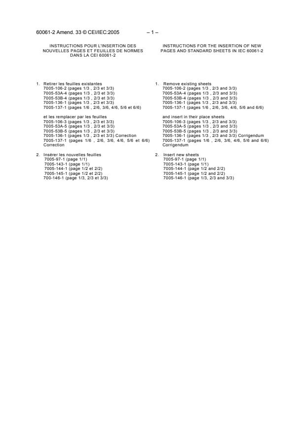
60061-2 Amend. 33 © CEI/IEC:2005 – 1 –
INSTRUCTIONS POUR L'INSERTION DES INSTRUCTIONS FOR THE INSERTION OF NEW
NOUVELLES PAGES ET FEUILLES DE NORMES PAGES AND STANDARD SHEETS IN IEC 60061-2
DANS LA CEI 60061-2
1. Retirer les feuilles existantes 1. Remove existing sheets
7005-106-2 (pages 1/3 , 2/3 et 3/3) 7005-106-2 (pages 1/3 , 2/3 and 3/3)
7005-53A-4 (pages 1/3 , 2/3 et 3/3) 7005-53A-4 (pages 1/3 , 2/3 and 3/3)
7005-53B-4 (pages 1/3 , 2/3 et 3/3) 7005-53B-4 (pages 1/3 , 2/3 and 3/3)
7005-136-1 (pages 1/3 , 2/3 et 3/3) 7005-136-1 (pages 1/3 , 2/3 and 3/3)
7005-137-1 (pages 1/6 , 2/6, 3/6, 4/6, 5/6 and 6/6)
7005-137-1 (pages 1/6 , 2/6, 3/6, 4/6, 5/6 et 6/6)
et les remplacer par les feuilles and insert in their place sheets
7005-106-3 (pages 1/3 , 2/3 et 3/3) 7005-106-3 (pages 1/3 , 2/3 and 3/3)
7005-53A-5 (pages 1/3 , 2/3 et 3/3) 7005-53A-5 (pages 1/3 , 2/3 and 3/3)
7005-53B-5 (pages 1/3 , 2/3 et 3/3) 7005-53B-5 (pages 1/3 , 2/3 and 3/3)
7005-136-1 (pages 1/3 , 2/3 et 3/3) Correction 7005-136-1 (pages 1/3 , 2/3 and 3/3) Corrigendum
7005-137-1 (pages 1/6 , 2/6, 3/6, 4/6, 5/6 et 6/6) 7005-137-1 (pages 1/6 , 2/6, 3/6, 4/6, 5/6 and 6/6)
Correction Corrigendum
2. Insérer les nouvelles feuilles 2. Insert new sheets
7005-97-1 (page 1/1) 7005-97-1 (page 1/1)
7005-143-1 (page 1/1) 7005-143-1 (page 1/1)
7005-144-1 (page 1/2 et 2/2) 7005-144-1 (page 1/2 and 2/2)
7005-145-1 (page 1/2 et 2/2) 7005-145-1 (page 1/2 and 2/2)
700-146-1 (page 1/3, 2/3 et 3/3) 7005-146-1 (page 1/3, 2/3 and 3/3)
60061-2 Amend. 33 © CEI/IEC:2005 – 1 –
AVANT-PROPOS
Le présent amendement a été établi par le sous-comité 34B: Culots et douilles, du
comité d’études 34 de la CEI: Lampes et équipements associés.
Le texte de cet amendement est issu des documents suivants
FDIS Rapport de vote
34B/1201/FDIS 34B/1207/RVD
Le rapport de vote indiqué dans le tableau ci-dessus donne toute information sur le
vote ayant abouti à l'approbation de cet amendement.
Le comité a décidé que le contenu de cet amendement et de la publication de base ne
sera pas modifié avant la date de maintenance indiquée sur le site web de la CEI
sous "http://webstore.iec.ch" dans les données relatives à la publication recherchée.
A cette date, la publication sera
• reconduite;
• supprimée;
• remplacée par une édition révisée, ou
• amendée.
__________
FOREWORD
This amendment has been prepared by subcommittee 34B: Lamp caps and holders, of
IEC technical committee 34: Lamps and related equipment.
The text of this amendment is based on the following documents:
FDIS Report on voting
34B/1201/FDIS 34B/1207/RVD
Full information on the voting for the approval of this amendment can be found in the
report on voting indicated in the above table.
The committee has decided that the contents of this amendment and the base
publication will remain unchanged until the maintenance result date indicated on the
IEC web site under "http://webstore.iec.ch" in the data related to the specific
publication. At this date, the publication will be
• reconfirmed,
• withdrawn,
• replaced by a revised edition, or
• amended.
_____________
60061-2 Amend. 33 © CEI/IEC:2005
HOLDERS
DOUILLES
W3x16q, WX3x16q & WY3x16q Page 1/3
Dimensions in millimetres - Dimensions en millimètres
The drawing is intended only to illustrate the dimensions essential for interchangeability.
Le dessin a pour seul but d’illustrer les dimensions essentielles pour l’interchangeabilité.
For details of bases W3x16q, WX3x16q and WY3x16q, see sheet 7004-106.
Pour les détails des socles W3x16q, WX3x16q and WY3x16q, voir feuille 7004-106.
Q1
(11)
(11)
J2 J2
W3x16q
(9)
H
JJ11
M
(5)
G
K C AM
(9)
Q2 (9)
AP E
Y Y
(11)
(5)
D/2 D/2
(10)
WX3x16q*
(12)
(5)
(12)
(9)
(9)
AA
(11)
J3 J3
(9)
(11)
(5)
(9)
(5)
(11)
BC BA
WY3x16q*
(11)
(5)
(9)
(9)
Y Y
BA BC
(10)
BB/2 BB/2
* For missing dimensions, see holder W3x16q.
* Pour les dimensions manquantes, voir douille W3x16q
IEC 60061-2
7005-106-3
CEI 60061-2
60061-2 Amend. 33 © CEI/IEC:2005
HOLDERS
DOUILLES
W3x16q, WX3x16q & WY3x16q Page 2/3
Dimensions in millimetres - Dimensions en millimètres
Dimension Min. Max.
C 3,5 --
D (2) 16,3 16,7
E (1) -- 5,5
G 6,7 --
H 8,6 --
J1 -- 1,8
J2 -- 4,3
J3 (6) 6,3 6,9
K 3,3 3,5
M 2,4 3,1
Q1 Nom. 11
Q2 Nom. 6
Y (8) 4,4 4,8
Y (7) 4,4 6,0
AA (6) 3,2 --
AM (1) 5,5 --
AP (3) 1,0 5,0
BA (4) 5,8 6,0
BB (4) 18,3 18,7
BC (4) 6,7 6,9
Nom. 50º
α
(1) Dimension AM denotes the width of the slot, which is applicable over height E.
(2) Applies to holders having rigid sides to centre the lamp base in the holder. In holder designs where this centring is achieved
by a spring force acting along the small sides of the lamp base, lower values for D are acceptable. In that case the
requirement is that a base of maximum width shall be able to enter. This shall be checked by means of gauge "A" shown on
sheet 7006-106A. Furthermore, a base of minimum width shall be centred.
Not applicable to holders WY3x16q
(3) This value denotes the area of electrical contact-making.
(4) Only applicable to lampholders WY3x16q.
(5) During insertion the retaining lugs shall slip over the highest points of the retention bosses of the base.
(6) Only applicable to lampholders WX3x16q.
(7) Only applicable to lampholders W3x16q.
(8) Not applicable to lampholders W3x16q.
(9) Contacts.
(10) Reference plane.
(11) Seating for reference boss.
(12) Key.
(1) La dimension AM, qui s'applique à toute la hauteur E, indique la largeur de la rainure.
(2) S'applique à des douilles ayant des parois rigides pour centrer les socles des lampes dans la douille. Des valeurs plus faibles
de D sont admis pour les douilles dont la conception prévoit le centrage par la force de ressorts agissant le long des petits
cotés du socle de la lampe. Dans ce dernier cas, il est exigé qu'un socle ayant la largeur maximale puisse entrer. Ceci sera
vérifié à l'aide du calibre "A" indiqué sur la feuille 7006-106A. Enfin, un socle ayant la largeur minimale devra aussi être
correctement centrée.
Ne s’applique pas aux douilles WY3x16q.
(3) Cette valeur indique la zone où se fait le contact électrique.
(4) Uniquement applicable aux douilles WY3x16q.
(5) Pendant l'insertion, les tenons de rétention doivent glisser sur les points les plus hauts des bossages de rétention du socle.
(6) Uniquement applicable aux douilles WX3x16q.
(7) Uniquement applicable aux douilles W3x16q.
(8) Ne s’applique pas aux douilles W3x16q.
(9) Contacts.
(10) Plan de référence.
(11) Appui pour le bossage de référence.
(12) Détrompeur.
IEC 60061-2
7005-106-3
CEI 60061-2
60061-2 Amend. 33 © CEI/IEC:2005
HOLDERS
DOUILLES
W3x16q, WX3x16q & WY3x16q Page 3/3
Dimensions in millimetres - Dimensions en millimètres
The minimum and maximum insertion forces and the minimum and maximum retention forces shall be checked by means of the
gauges shown on sheet 7006-106A.
The force required to effect insertion and engagement of gauge "A" shall not exceed 60 N.
The force required to effect complete withdrawal of gauge "A" shall not exceed 60 N.
The force required to effect insertion and engagement of gauge "B" shall not be less than 10 N.
The force required to effect withdrawal of gauge "B" shall not be less than 10 N.
Les forces minimales et maximales d'insertion et les forces minimales et maximales de rétention doivent être vérifiées au moyen
des calibres décrits dans la feuille 7006-106A.
La force nécessaire pour effectuer l'insertion et l'encliquetage du calibre "A" ne doit pas excéder 60 N.
La force nécessaire pour extraire complètement le calibre "A" ne doit pas excéder 60 N.
La force nécessaire pour effectuer l'insertion et l'encliquetage du calibre "B" ne doit pas être inférieure à 10 N.
La force nécessaire pour retirer le calibre "B" ne doit pas être inférieure à 10 N.
IEC 60061-2
7005-106-3
CEI 60061-2
60061-2 Amend. 33 © CEI/IEC:2005
CONNECTOR/HOLDER
CONNECTEUR/DOUILLE
GX8.5 Page 1/1
Dimensions in millimetres - Dimensions en millimètres
The drawing is intended only to illustrate the dimensions essential for interchangeability.
Le dessin a pour seul but d’illustrer les dimensions essentielles pour l’interchangeabilité.
For details of base GX8.5, see sheet 7004-143.
Pour les détails du socle GX8.5, voir feuille 7004-143.
C
B1
H
B
R
(1)
N1
K N
F2
F1
(2)
D
ØA
α
(6)
E1
E2
(1) Reference plane. The reference plane need not be continuous.
(2) Outer side contacts only. No inner side contacts allowed and no bottom contacts allowed.
(3) Dimensions C and H delineate the demarcation between the space which may be occupied by parts of the lamp and the
space which may be occupied by rigid parts of the connector/holder and/or luminaire.
(4) To be checked by means of the gauge shown on sheet 7006-143A.
(5) The maximum insertion and withdrawal torques are xxx Nm (under consideration) and shall be checked with the gauge shown
on sheet 7006-143A.
The minimum withdrawal torque is xxx Nm (under consideration) and shall be checked with the gauge shown on sheet
7006-143B.
(6) Dimension E1min to be maintained over area described by angle α.
(7) Dimension B1 is applicable in the area between N and N1.
(1) Plan de référence. Il n’est pas nécessaire que le plan de référence soit continu.
(2) Uniquement contacts latéraux.externes. Aucun contact interne et de fond
est permis.
Dimension Min. Max.
(3) Les dimensions C et H définissent la délimitation entre l’espace qui peut
A 5,5 --
être occupé par des parties de la lampe et l’espace susceptible d’être occupé
B 21,7 22,4
par des parties rigides du connecteur/douille et/ou du luminaire.
B1 (7) 25,4 --
(4) A vérifier au moyen du calibre représenté sur la feuille 7006-143A.
C (3) 26
(5) Les torsions maximales d’insertion et d’extraction sont xxx Nm (à l'étude)
D (4) 8,5
et doivent être vérifiées avec le calibre représenté sur la feuille 7006-143A.
E1 4,8 (6) 5,2
Le couple d’extraction minimal est de xxx Nm (à l'étude) et doit être contrôlé
E2 11,8 12,2
avec le calibre défini dans feuille de norme 7006-143B.
F1 7,8 --
(6) La dimension E1 min. doit être respectée dans la zone définie par l’angle
F2 2,3 2,7
α.
H (3) 25 (7) La dimension B1 est respectée dans la zone entre N et N1.
K 0,8 1,0
GAUGING: Connectors GX8.5 shall fulfil the tests of the gauges shown on
N (7) 1 3,4
sheets 7006-143A, 7006-143B and 7006-143C.
N1 (7) 6,5
VERIFICATION: Les connecteurs GX8.5 doivent satisfaire aux essais avec
R -- 2,2
les calibres selon les feuilles 7006-143A, 7006-143B et 7006-143C.
α (6) 75° 90°
IEC 60061-2
7005-143-1
CEI 60061-2
60061-2 Amend. 33 © CEI/IEC:2005
LAMPHOLDER
DOUILLE
GX10 Page 1/2
Dimensions in millimetres - Dimensions en millimètres
The drawing is intended only to illustrate the dimensions essential for interchangeability.
Le dessin a pour seul but d’illustrer les dimensions essentielles pour l’interchangeabilité.
For details of base GX10, see sheet 7004-144.
Pour les détails du socle GX10, voir feuille 7004-144.
(5)
G
I
O
F2
F1
(3) (4)
α3
α
M
K
α4
D
(5)
A
E1
E2
H
Dimension Min. Max.
(1) To be checked by means of the gauge shown on sheet 7006-144.
A 5,5 --
(2) Dimensions G, H, I and K delineate the demarcation between the space
D(1) 10
which may be occupied by parts of the lamp and the space which may be
E1 6,3 6,7
occupied by parts of the lampholder and/or luminaire.
E2 13,3 13,7 (3) The distance from the top edge of the contacts to the reference plane shall
not be greater than 2,9 mm.
F1 6,6 --
(4) Side contacts only. No bottom contacts allowed.
F2 2,3 2,7
(5) Reference plane. The reference plane need not be continuous.
G(2) 12
(6) The maximum insertion and withdrawal torques are checked with the gauge
H(2) 22,6
shown on sheet 7006-144.
I(2)(7) 4,6
(7) Dimensions I and K apply over angle α3
K(2)(7) 19,6
M -- 20,0
O 4,3 --
α -- 75°
α3(1)(7) 50° 57°
α4(1) 40°30' 41°30'
IEC 60061-2
7005-144-1 CEI 60061-2
60061-2 Amend. 33 © CEI/IEC:2005
LAMPHOLDER
DOUILLE
GX10 Page 2/2
Dimensions in millimetres - Dimensions en millimètres
(1) A vérifier au moyen du calibre représenté sur la feuille 7006-144.
(2) Les dimensions G, H, I and K définissent la délimitation entre l’espace qui peut être occupé par des parties de la lampe et
l’espace susceptible d’être occupé par des parties de la douille et/ou du luminaire.
(3) Le rebord supérieur des contacts doit se trouver à une distance inférieure ou égale à 2,9 mm du plan de référence.
(4) Uniquement contacts latéraux. Aucun contact de fond est permis.
(5) Plan de référence. Le plan de référence n’est pas nécessairement continu.
(6) Les torsions maximales d’insertion et d’extraction sont vérifiées avec le calibre représenté sur la feuille 7006-144.
(7) Les dimensions I et K concernent la zone correspondant à l’angle α3.
GAUGING: Lampholders GX10 shall fulfil the tests of the gauge shown on sheet 7006-144.
VERIFICATION: Les douilles GX10 doivent satisfaire aux essais avec le calibre selon la feuille 7006-144.
IEC 60061-2
7005-144-1 CEI 60061-2
60061-2 Amend. 33 © CEI/IEC:2005
LAMPHOLDER
DOUILLE
GY10 Page 1/2
Dimensions in millimetres - Dimensions en millimètres
The drawing is intended only to illustrate the dimensions essential for interchangeability.
Le dessin a pour seul but d’illustrer les dimensions essentielles pour l’interchangeabilité.
For details of base GY10, see sheet 7004-145.
Pour les détails du socle GY10, voir feuille 7004-145.
(5)
G
I
O
F2
F1
(3) (4)
α3
α
α4
M
K
D
(5)
A
E1
E2
H
(1) To be checked by means of the gauge shown on sheet 7006-145.
Dimension Min. Max.
(2) Dimensions G H, I and K delineate the demarcation between the space
A 5,5 --
which may be occupied by parts of the lamp and the space which may be
D(1) 10
occupied by parts of the lampholder and/or luminaire.
E1 6,3 6,7
(3) The distance from the top edge of the contacts to the reference plane shall
E2 13,3 13,7 not be greater than 2,9 mm.
(4) Side contacts only. No bottom contacts allowed.
F1 6,6 --
(5) Reference plane. The reference plane need not be continuous.
F2 2,3 2,7
(6) The maximum insertion and withdrawal torques are checked with the gauge
G(2) 12
shown on sheet 7006-145.
H(2) 22,6
(7) Dimensions I and K apply over angle α3
I(2)(7) 4,6
K(2)(7) 19,6
M -- 20,0
O 4,3 --
α -- 75°
α3(1)(7) 30° 37°
α4(1) 60°30' 61°30'
IEC 60061-2
7005-145-1
CEI 60061-2
60061-2 Amend. 33 © CEI/IEC:2005
LAMPHOLDER
DOUILLE
GY10 Page 2/2
Dimensions in millimetres - Dimensions en millimètres
(1) A vérifier au moyen du calibre représenté sur la feuille 7006-145.
(2) Les dimensions G, H. I et K définissent la délimitation entre l’espace qui peut être occupé par des parties de la lampe et
l’espace susceptible d’être occupé par des parties de la douille et/ou du luminaire.
(3) Le rebord supérieur des contacts doit se trouver à une distance inférieure ou égale à 2,9 mm du plan de référence.
(4) Uniquement contacts latéraux. Aucun contact de fond est permis.
(5) Plan de référence. Le plan de référence n’est pas nécessairement continu.
(6) Les torsions maximales d’insertion et d’extraction sont vérifiées avec le calibre représenté sur la feuille 7006-145.
(7) Les dimensions I et K concernent la zone correspondant à l’angle α3.
GAUGING: Lampholders GY10 shall fulfil the tests of the gauge shown on sheet 7006-145.
VERIFICATION: Les douilles GY10 doivent satisfaire aux essais avec le calibre selon la feuille 7006-145.
IEC 60061-2
7005-145-1
CEI 60061-2
60061-2 Amend. 33 © CEI/IEC:2005
HOLDERS
DOUILLES
PGJY19 Page 1/3
Dimensions in millimetres - Dimensions en millimètres
The drawing is intended only to illustrate the dimensions essential for interchangeability.
Le dessin a pour seul but d’illustrer les dimensions essentielles pour l’interchangeabilité.
For details of caps PGJY19, see sheet 7004-….
Pour les détails des culots PGJY19, voir feuille 7004-….
(8)
(5)
30°(2x)
≅60°
J
Q(3)
a
(7)
A
A
R
E(3x)
(11)
ØA1 (10)
ØN
(12)
(1)
X
(4)(5)
T
D(13)
W
(14)
a
r
(11)
H
(9)
(15)
R1(2)
P
a
Only the PGJY19-1 holder is shown. For missing dimensions and different designations, see following pages.
Seule la douille PGJY19-1 est représentée. Pour les dimensions manquantes et les désignations différentes, voir pages
suivantes.
IEC 60061-2
7005-146-1
CEI 60061-2
60061-2 Amend. 33 © CEI/IEC:2005
HOLDERS
DOUILLES
PGJY19 Page 2/3
Dimensions in millimetres - Dimensions en millimètres
Dimension Min. Max.
A (1) 9,5
A1 19,5 20,0
D 5,85 6,15
E 1,8 2,0
H 0,25 0,35
J 2,5 --
N 32 --
P 1,0 1,2
Q (3)
R 12,4 12,5
R1 (2) 10,0 10,1
T 2,6 (16) 3
W (13) 7,4 7,8
X 23 --
a Approx. 3
r 0,8 1,0
Operating position.
To optimize lamp operating and contact conditions, the holder should be oriented in such a way that in the final seating position the
cap contacts are pointing downwards.
(1) V-support. The supporting areas for the cap are formed by two tangents to a circle having a diameter of 19 mm. During
insertion the lamp is pushed into this V-shaped support by means of a spring in the lamp(cap) with a minimum force of 10 N
(under consideration). Only after the lamp-cap has been pushed into the V-shaped support, a further axial force of 5 N minimum
(under consideration) shall be applied, pressing the cap reference plane against the holder reference plane.
(2) The centre point for radius R1 is formed by the crossing of two lines at distance A from the V-support (the theoretical lamp
axis).
(3) Dimension Q is 4,1 ± 0,1 mm for lampholders PGJY19-1, PGJY19-2 and PGJY19-4.
Dimension Q is 5,15 ± 0,1 mm for lampholders PGJY19-3.
Dimension Q is 6,2 ± 0,1 mm for lampholders PGJY19-5.
(4) The transition from the V-support to the reference plane shall have a radius between 0,2 mm and 1 mm or an equivalent
chamfer.
(5) Reference plane. The reference plane is formed by three flat areas (hachured in the drawing) having dimensions of
approximately 3 mm x 3 mm. Outside these areas and within a circle with a diameter of 25 mm no parts shall protrude from the
reference plane. An exception is made for the stop.
(6) The reflector entrance shall be so designed that the lamp can be inserted and rotated to the intended position only.
(7) Smooth surface required in this area because of lamp spring action.
(8) Direction of lampcap-spring force.
(9) Lampcap spring shown after complete insertion of the lamp.
(10) Direction of lamp insertion (bulb first).
(11) Stop. The stop function may alternatively be provided by the contact section
(12) Ramps, to facilitate insertion of the lamp.
(13) Measured from the centre lines of the female contacts.
(14) Holder contacts. The contacts shall be free floating to avoid axial forces on the lamp. They shall accept and make electrical
contact with all allowable combinations of lamp contact tab positions. Values for the maximum insertion and removal forces
are under consideration.
(15) Retention indent, to prevent loosening of the lamp and to give a feeling (click) when the final seating position has been
reached.
(16) Increase of this value to 2.8 mm is under consideration.
Position d'opération.
Pour optimiser les positions de fonctionnement et de contact de la lampe, la douille doit être orientée de telle façon que dans la
position finale d’utilisation, les contacts du culot sont orientés vers le bas.
(1) Support V. Les zones supportant le culot sont formées par deux tangentes à un cercle ayant un diamètre de 19 mm. Pendant
l'introduction la lampe est poussée dans ce support en V au moyen du ressort du culot de la lampe avec une force minimale de 10
N (à l'étude). Uniquement lorsque le culot a été poussé dans le support V, une autre force axiale de 5 N minimale (à l'étude) doit
être appliquée en pressant le plan de référence de la lampe contre la surface de référence de la douille.
(2) Le centre du rayon R1 est formé par l'intersection de deux lignes à la distance A du support en V (l'axe théorique de la
lampe).
(3) La dimension Q est de 4,1 ± 0,1 mm pour les douilles PGJY19-1, PGJ19-2 and PGJY19-4.
La dimension Q est de 5,15 ± 0,1 mm pour les douilles PGJY19-3.
La dimension Q est de 6,2 ± 0,1 mm pour les douilles PGJY19-5.
(4) Le passage du support en V au plan de référence devra avoir un rayon compris entre 0,2 et 1 mm ou un chanfrein équivalent.
IEC 60061-2
7005-146-1
CEI 60061-2
60061-2 Amend. 33 © CEI/IEC:2005
HOLDERS
DOUILLES
PGJY19 Page 3/3
Dimensions in millimetres - Dimensions en millimètres
(5) Plan de référence. Le plan de référence est constitué par les trois zones plates (hachurées sur le dessin) ayant
approximativement une dimension de 3 mm x 3 mm. A l'extérieur de ces zones et à l'intérieur d'un cercle de diamètre 25 mm
aucune partie ne doit dépasser le plan de référence. Une exception est tolérée pour la butée.
(6) La découpe dans le réflecteur doit être conçue de telle façon que le passage de la lampe ne puisse qu'uniquement être
réalisé dans la position désirée.
(7) Surface lisse pour joint de scellement.
(8) Direction de la force de ressort du culot.
(9) Ressort du culot après introduction totale de la lampe.
(10) Direction d'introduction de la lampe (ampoule d'abord).
(11) Butée. La fonction d’arrêt peut être assurée alternativement par la zone de contact.
(12) Pentes, pour faciliter l’introduction de la lampe.
(13) Mesurés à partir des axes centraux des contacts femelles.
(14) Contacts douilles. Les contacts doivent être libres et flottant pour éviter des efforts axiaux sur la lampe. Ils doivent
permettrent et réaliser le contact électrique dans toutes les combinaisons permises des positions de la languette de
connexion de la lampe. Les valeurs des forces maximales d’introduction et d’extraction sont à l’étude.
(15) Bossage d'arrêt, pour éviter tout dégagement de la lampe et donner un signal (click) lorsque la position finale d’utilisation a
été atteinte.
(16) L’augmentation de cette valeur à 2.8 mm est à l’étude.
B
B
B
B2
PGJY19-1 PGJY19-2 PGJY19-3
B1 B1
(11) (11) (11)
60° 60° 60°
B6
B3 B4
B5
60° 60° 60°
B B B
B1
B1 B1
B B
B1 B1
PGJY19-4 PGJY19-5
(11) (11)
60° 60°
B5
B3
B6
60° 60°
B
B
B2
B1
Dimension Min. Max.
B 8,1 8,3
B1 3,7 3,9
B2 5,7 5,9
B3 8,2 8,4
B4 10,2 10,4
B5 6,1 6,2
B6 4,1 4,2
IEC 60061-2
7005-146-1
CEI 60061-2
60061-2 Amend. 33 © CEI/IEC:2005
HOLDERS
DOUILLES
SX4s Page 1/1
Dimensions in millimetres - Dimensions en millimètres
The drawing is intended only to illustrate the dimensions essential for interchangeability.
Le dessin a pour seul but d’illustrer les dimensions essentielles pour l’interchangeabilité.
For details of caps SX4s, see sheet 7004-97.
Pour les détails des culots SX4s, voir feuille 7004-97.
(3)
(4)
(2)
ØA
E
J
(1)
H
(5)
ØB
(1) Reference plane. The reference plane may consist of three longitudinal-bearing ridges (equally spaced circumferentially).
(2) In many applications, a cover or lens is attached directly to the inner section of the lampholder. In such an
arrangement, space shall be provided for the bulb of the lamp to ensure interchangeability of lamps.
(3) Where separate parts are used to provide dimensions A and B, the engagement surface shall provide electrical continuity and
mechanical stability by means of mating screw threads or equally effective features.
(4) Insulation layer should be provided for those applications where mounting case is not part of the electrical return circuit.
(5) Position of the central contact when the lamp is fully inserted.
(6) The relation between dimensions B, E and J shall be as follows:
a) In lampholder designs requiring the lamp to be inserted from the bulb end of the holder, diameter B shall be applicable over the
full length of dimension J.
b) In lampholders permitting insertion of the lamp from the centre contact end of the holder, dimension B shall be applicable only
over that portion of dimension J that is not in the zone described by dimension E.
(7) Dimension E is the length over which dimension A applies.
(1) Plan de référence. Le plan de référence peut être constitué par les trois ergots supports longitudinaux (également espacée
sur la circonférence).
(2) Dans beaucoup d’applications, un capot ou une lentille sont fixés directement à la partie intérieure de la douille. Dans ce cas,
un espace doit être prévu pour l’ampoule de la lampe afin d’assurer l’interchangeabilité.
(3) Lorsque des parties distinctes sont mises en œuvre pour les dimensions A et B, la surface d’introduction doit assurer la
continuité électrique ainsi qu’une stabilité mécanique au moyen d’un assemblage par filetage à vis ou tout dispositif assurant une
fonction équivalente.
(4) Une couche isolante devrait être prévue pour les applications dont la structure de montage n’est pas reliée au circuit
électrique de retour.
(5) Position du contact central lorsque la lampe est complètement introduite.
(6) La relation entre les dimensions B, E et J doivent être les suivantes :
a) Pour les concepts de douilles nécessitant que la lampe soit introduite par l’extrémité de l’ampoule, le diamètre B doit être
respecté sur toute la longueur de la dimension J.
b) Pour les douilles permettant l’introduction de la lampe du côté du contact central, la dimension B doit s’appliquer
uniquement sur la partie de la dimension J qui n’est pas dans la zone définie
par la dimension E.
Dimension Min. Max.
(7) La dimension E est la longueur sur laquelle la dimension A s’applique.
A 4,06 4,22
B (6) 4,83 --
E (6)(7) 2,28 3,05
H Nom. 3,05
J (5)(6) 4,19 5,31
IEC 60061-2
7005-97-1 CEI 60061-2
60061-2 Amend. 33 © CEI/IEC:2005
PRINTED CIRCUIT CONNECTORS
CONNECTEURS POUR CIRCUIT IMPRIME
GZX7d-., GZY7d-. & GZZ7d-. Page 1/3
Dimensions in millimetres - Dimensions en millimètres
The drawing is intended only to illustrate the dimensions essential for interchangeability.
Le dessin a pour seul but d’illustrer les dimensions essentielles pour l’interchangeabilité.
For details of GZX7d-., GZY7d-. and GZZ7d-. caps, see sheet 7004-136
Pour les détails des culots GZX7d-., GZY7d-. et GZZ7d-., voir feuille 7004-136.
K3
Single module connector with key -1
K1
Connecteur de module unitaire avec le détrompeur -1.
D2 D
D1 K2
c c
b
G(4)
(2)
a
E(2x) R2
J
a
A1
B
c-c
F
R
N1
H
α
L
b O
β
P1 P3
P2
(1)
(3)
γ
c c
c-c
Single module connector with key -2. N2
All other dimensions are the same as above.
Connecteur de module unitaire avec le détrompeur –2.
Toutes les autres dimensions sont identiques à celles ci-dessus.
IEC 60061-2
7005-136-1
CEI 60061-2
60061-2 Amend. 33 © CEI/IEC:2005
PRINTED CIRCUIT CONNECTORS
CONNECTEURS POUR CIRCUIT IMPRIME
GZX7d-., GZY7d-. & GZZ7d-. Page 2/3
Dimensions in millimetres - Dimensions en millimètres
Dimension Min. Max.
A1 6,3 --
B (GZX7d-.)(4) -- 1
B (GZY7d-.)(4) -- 1
B (GZZ7d-.)(4) Approx. 0 (5)
D 1,1 1,3
D1 2,1 2,5
D2 6,3 7,1
E 1,4 1,5
F (GZX7d-.)(4) 0,8 1,1
F (GZY7d-.)(4) 0,8 1,1
F (GZZ7d-.)(4) Approx. 0 (6)
G*(GZX7d-.)(4) 1,75 --
G*(GZY7d-.)(4) 1,15 --
G (GZZ7d-.)(4) 0,45 0,6
H 1,8 1,9
J 2 --
K1 4 --
K2 1 1,5
K3 8,5 --
L 8,9 9,1
N1 (key -1)(3) 1,45 1,55
N2 (key -2)(3) 3,45 3,55
O 0,95 1,05
P1 (GZX7d-.)(4) 2,9 3,1
P1 (GZY7d-.)(4) 2,4 2,6
P1 (GZZ7d-.)(4) 1,6 1,8
P2 (GZX7d-.)(4) 1,75 1,9
P2 (GZY7d-.)(4) 1,15 1,3
P2 (GZZ7d-.)(4) 0,45 0,6
P3 (4) 0,4 0,7
R (7) 1,15 1,25
R2 3,8 3,9
--
α 45°
β 95° 110°
γ 90° 105°
(1) Reference line.
(2) Retention
...