


ISO 8878:1987
(Main)Information processing systems — Data communications — Use of X.25 to provide the OSI connection-mode network service
Information processing systems — Data communications — Use of X.25 to provide the OSI connection-mode network service
Systèmes de traitement de l'information — Communication de données — Utilisation du protocole X.25 pour fournir le service de réseau OSI en mode connexion
General Information
- Status
- Withdrawn
- Publication Date
- 31-Aug-1987
- Withdrawal Date
- 31-Aug-1987
- Current Stage
- 9599 - Withdrawal of International Standard
- Start Date
- 30-Dec-1992
- Completion Date
- 12-Feb-2026
Relations
- Effective Date
- 06-Jun-2022
- Effective Date
- 06-Jun-2022
- Effective Date
- 06-Jun-2022
- Effective Date
- 06-Jun-2022
- Effective Date
- 15-Apr-2008
- Effective Date
- 18-Dec-2008
- Effective Date
- 18-Dec-2008
- Effective Date
- 18-Dec-2008
- Effective Date
- 15-Apr-2008
Get Certified
Connect with accredited certification bodies for this standard

BSI Group
BSI (British Standards Institution) is the business standards company that helps organizations make excellence a habit.

NYCE
Mexican standards and certification body.
Sponsored listings
Frequently Asked Questions
ISO 8878:1987 is a standard published by the International Organization for Standardization (ISO). Its full title is "Information processing systems — Data communications — Use of X.25 to provide the OSI connection-mode network service". This standard covers: Information processing systems — Data communications — Use of X.25 to provide the OSI connection-mode network service
Information processing systems — Data communications — Use of X.25 to provide the OSI connection-mode network service
ISO 8878:1987 is classified under the following ICS (International Classification for Standards) categories: 35.100.30 - Network layer. The ICS classification helps identify the subject area and facilitates finding related standards.
ISO 8878:1987 has the following relationships with other standards: It is inter standard links to ISO 8878:1987/Add 2:1990, ISO 8878:1987/Amd 3:1991, ISO 8878:1987/Add 1:1990, ISO 8878:1987/Cor 4:1991, ISO/IEC 8878:1992; is excused to ISO 8878:1987/Amd 3:1991, ISO 8878:1987/Add 2:1990, ISO 8878:1987/Add 1:1990, ISO 8878:1987/Cor 4:1991. Understanding these relationships helps ensure you are using the most current and applicable version of the standard.
ISO 8878:1987 is available in PDF format for immediate download after purchase. The document can be added to your cart and obtained through the secure checkout process. Digital delivery ensures instant access to the complete standard document.
Standards Content (Sample)
IS0
INTERNATIONAL STANDARD
First edition
1987-09-01
INTERNATIONAL ORGANIZATION FOR STANDARDIZATION
ORGANISATION INTERNATIONALE DE NORMALISATION
MEXAYHAPOAHAR OPrAHM3AuMR Il0 CTAHAAPTMSAUMM
Information processing systems - Data
communications - Use of X.25 to provide
the OS1 connection-mode network service
Systèmes de traitement de l'information - Communication de données - Utifisation du
protocole X.25 pour fournir le service de réseau OS1 en mode connexion
Reference number
[SO 8878 : 1987 (E)
Foreword
IS0 (the International Organization for Standardization) is a worldwide federation of
national standards bodies (IS0 member bodies). The work of preparing International
Standards is normally carried out through IS0 technical committees. Each member
body interested in a subject for which a technical committee has been established has
the right to be represented on that committee. International organizations, govern-
mental and non-governmental, in liaison with EO, also take part in the work.
e
Draft International Standards adopted by the technical committees are circulated to
the member bodies for approval before their acceptance as International Standards by
the IS0 Council. They are approved in accordance with IS0 procedures requiring at
least 75 % approval by the member bodies voting.
International Standard IS0 8878 was prepared by Technical Committee ISO/TC 97,
Information processing systems.
Users should note that all International Standards undergo revision from time to time
and that any reference made herein to any other International Standard implies its
latest edition, unless otherwise stated.
O International Organization for Standardization, 1981 O
Printed in Switzerland
II
IS0 8878 : 19û7 (E)
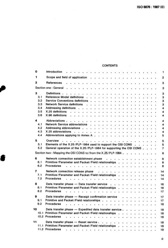
CONTENTS
O Introduction . 1
1 Scope and field of application . 2
2 References . 3
Section one : General . 3
3 Definitions . 3
3.1 Reference Model definitions . 3
3.2 Service Conventions definitions . 3
3.3 Network Service definitions . 3
3.4 Addressing definitions . 4
3.5 X.25 definitions .
3.6 X.96 definitions . 4
4 Abbreviations . 4
4.1 Network Service abbreviations . 4
4.2 Addressing abbreviations . 4
4.3 X.25 abbreviations . 4
4.4 Abbreviations applying to Annex A . 5
5 5
Overview .
5.1 Elements of the X.25/PLP-1984 used to support the OS1 CONS . 5
5.2 General operation of the X.25/PLP-1984 for supporting the OS1 CONS .
Section two : Mapping the OS1 CONS to/from theX.25/PLP-1984 . 8
6 Network connection establishment phase . 8
6.1 Primitive/Parameter and Packet/Field relationships . 8
.......................
6.2 Procedures 8
7 Network connection release phase . 14
7.1 Primitive/Parameter and Packet/Field relationships . 14
.......................
7.2 Procedures 14
8 Data transfer phase . Data transfer service . 16
8.1 Primitive/Parameter and Packet/Field relationships . 16
.......................
8.2 Procedures 17
9 Data transfer phase . Receipt confirmation service . 17
/ Field relationships . 17
9.1 Primitive and Packet
.......................
9.2 Procedures 18
10 Data transfer phase . Expedited data transfer service .
10.1 Primitive/Parameter and PacketiField relationships . 18
10.2 Procedures . 18
11 Data transfer phase . Reset service . 18
11.1 PrimitiveIParameter and Packet/Field relationships . 18
1 1.2 Procedures . 19
iii
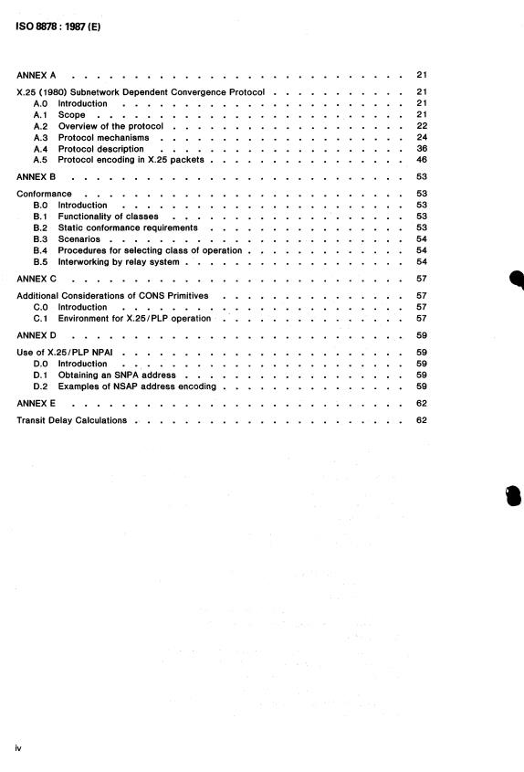
IS0 8878 : 1987 (E)
ANNEX A .
X.25 (1 980) Subnetwork Dependent Convergence Protocol
A.0 Introduction .
A.l Scope .
A.2 Overview of the protocol .
A.3 Protocol mechanisms .
A.4 Protocol description .
A.5 Protocol encoding in X.25 packets .
ANNEX B .
Conformance .
B.0 Introduction . 53
B.l Functionality of classes . 53
8.2 Static conformance requirements . 53
B.3 Scenarios . 54
B.4 Procedures for selecting class of operation 54
B.5 lnterworking by relay system .
ANNEX C .
Additional Considerations of CONS Primitives . .
C.0 Introduction . 57
C.l Environment for X.25/PLP operation . . 57
ANNEX D . 59
Use of X.25/PLP NPAl .
D.0 Introduction . 59
D.1 Obtaining an SNPA address .
D.2 Examples of NSAP address encoding . .
ANNEX E . 62
Transit Delay Calculations . 62
iv
IS0 8878 : 1987 (E)
INTERNATIONAL STANDARD
Information processing systems - Data
communications - Use of X.25 to provide
the OS1 connection-mode network service
O Introduction
This International StanLard defines two methods for providing the OS1 Connection-Mode NE. nrork Service
(CONS) through the use of the X.25 Packet Level Protocol (X.25/PLP). The first method, which is presented in
the main body of this International Standard, specifies a mapping between elements of the 1984 version of the
X.25/PLP (X.25/PLP-1984) and elements of the OS1 CONS. The second method, which is presented in Annex A
of this International Standard, defines a Subnetwork Dependent Convergence Protocol (SNDCP) that shall be
used to provide the OS1 CONS over subnetworks or with equipment using the 1980 version of the X.25/PLP. This
SNDCP should only be used if the elements of the X.25/PLP-1984, as defined in 5.1 of this International
Standard, are not available to support the OS1 CONS.
Annex B gives the conformance requirements for equipment providing the OS1 CONS by one or more of the
methods in this International Standard and defines the possibilities and rules for interworking between such
equipment.
Annexes A and B are integral parts of this International Standard. They are intended to provide a migration
strategy towards the use of the 1984 version of X.25 in both subnetworks and DTEs. Their status will be
reviewed periodically.
Annex C provides additional considerations on the relationship between the X.25 protocol procedures and the
CONS primitives.
Annex D illustrates the use of X.25 Network Protocol Address Information (NPAI), i.e., the Address Field and
the Address Extension Facilities.
Annex E illustrates the use of X.25 transit delay facilities.
The above three annexes are not integral parts of this International Standard.
The relationship between the X.25/PLP-1984 and the OS1 CONS is shown in Figure 1. This relationship is
described only in terms of the Network Layer entities that provide the CONS. No discussion is given here to
describe the actions of a Network Layer entity that only provides a relay function for a given network connection.
The OS1 Network Service is defined in terms of:
a. the primitive actions and events of the Service;
b. the parameters associated with each primitive action and event, and the form which they take; and
c. the interrelationship between, and the valid sequences of, these actions and events.
The OS1 Network Service does not specify individual implementations or products nor does it constrain the
implementation of entities and interfaces within a computer system.
The X.25/PLP-1984 is defined in terms of:
a. procedures for Virtual Calls and Permanent Virtual Circuits;
b. formats of packets associated with these procedures; and
c. procedures and formats for optional user facilities and CCITT-Specified DTE facilities.
k f
TRANSPORT TRANSPORT
- - USES SERVICE- - 1
PROTO COL LAYER
+
NETWORK SERVICE
X.25 PACKET NETWORK
J
- - PROVIDES SERVICE-
LEVEL
LAYER
PROTOCOL
i
IS0 8878 : 1987 (E)
The X.25/PLP-1984 or X.25/PLP-1980 with the SNDCP is usually regarded as operating between an end
system (i.e., a "Data Terminal Equipment" in X.25 terminology) and a packet-switched public data subnetwork.
However, the X.25/PLP-1984 or X.25/PLP-1980 with the SNDCP can also be used in other environments to
provide the OS1 CONS. Examples of such other uses include:
a. an end system connected to an X.25 packet-switched private data subnetwork;
b. an end system connected to a local area network;
c. direct connection or circuit-switched connection (including connection across a circuit-switched data
subnetwork) of two end systems without an intervening packet-switched public data subnetwork; and
d. an end system connected to an Integrated Services Digital Network.
2 References
IS0 7498, Information processing systems - Open Systems Interconnection - Basic Reference Model.
IS0 8208, Information processing systems - Data communications - X.25 Packet Level Protocol for Data
Terminal Equipment.
IS0 8348, Information processing systems - Data communications - Network service definition.
IS0 8348iAdd. 2, Information processing systems - Data communications - Network service definition -
Addendum 2: Network layer addressing.
IS0 / TR 8509, Information processing systems - Open Systems Inferconnection - Service conventions.
CClTT Recommendation X.25, Interface Between Data Terminal Equipment (DTE) and Data Circuit Terminating
Equipment (DCE) for Terminals Operafing in the Packet Mode and Connected to Public Data Networks by
Dedicated Circuit, 1984 (Red Book).
CClTT Recommendation X.96, Call Progress Signals in Public Data Networks, 1984 (Red Book).
SECTION ONE: GENERAL
3 Definitions
3.1 Reference Model definitions
The following concepts, developed and defined in the OS1 Reference Model (IS0 74981, are used:
a. Network connection
b. Network Layer
c. Network Service
d. Network Service Access Point
Network Service Access Point address
e.
f. Subnetwork
3.2 Service Conventions definitions
The following terms, as they apply to the Network Layer and as defined in the Service Conventions Standard
(ISO/TR 85091, are used:
a. Network Service user
b. Network Service provider
c. primitive
d. request
e. indication
f. response
g. confirm
3.3 Network Service definitions
The following terms, as defined in the Network Service (IS0 83481, are used:
a. Calling Network Service user
IS0 8878 : 1987 (E)
b. Called Network Service user
3.4 Addressing definitions
The following concepts, as defined in IS0 8348lAdd. 2, are used:
a. Subnetwork Point of Attachment address
b. Network Protocol Address Information
c. Initial Domain Part
d. Authority and Format Identifier
e. Initial Domain Identifier
f. Domain Specific Part
3.5 X.25 definitions
The following concepts, as developed in the X.25 Packet Level Protocol for DTEs (IS0 8208) and in CCITT
Recommendation X.25, are used:
a. virtual circuit
b. Virtual Call
c. logical channel
d. Packet Level
e. Data Terminal Equipment
f. Data Circuit-terminating Equipment
g. DXE (either a DTE or a DCE)
3.6 X.96 definitions
The following terms, as defined in CCITT Recommendation X.96, are used:
a. Category C call progress signal
b. Category D call progress signal
4 Abbreviations
4.1 Network Service abbreviations
CONS Connection-Mode Network Service
N Network
NC Network-connection
NL Network Layer
NS Network Service
Network Service Access Point
NSAP
Open Systems Interconnection
os1
Quality of Service
QOS
4.2 Addressing abbreviations
AFI Authority and Format Identifier
DSP Domain Specific Part
ID1 Initial Domain Identifier
IDP Initial Domain Part
NPAl Network Protocol Address Information
SNPA Subnetwork Point of Attachment
4.3 X.25 abbreviations
AEF Address Extension Facility
AF Address Field
D-bit Delivery Confirmation bit
IS0 8878 : 1987 (E)
DCE Data Circuit-terminating Equipment
Data Terminal Equipment
DTE
EDN Expedited Data Negotiation (Facility)
End-to-End Transit Delay Negotiation (Facility)
EETDN
Facility Parameter Field
FPF
General Format Identifier
GFI
Logical channel
LC
M-bit More Data bit
MBS M-bit Sequence
MTCN Minimum Throughput Class Negotiation (Facility)
PLP Packet level protocol
Packet receive sequence number
P(R)
Packet send sequence number
P(S)
Throughput Class Negotiation (Facility)
TCN
Transit Delay Selection And Indication (Facility)
TDSAI
Virtual Call
vc
4.4 Abbreviations applying to Annex A
AE Address Extension (parameter)
ID Identifier
LI Length Indicator
MTC Minimum Throughput Class (parameter)
N-CC Network Connection confirm
Network Connection request
N-CR
N-DR Network Disconnect request
Network Protocol Data Unit
NPDU
NSDU Network Service Data Unit
PT Parameter Type
PV Parameter Value
Q-bit Qualifier Bit
SNDCP Subnetwork Dependent Convergence Protocol
5 Overview
The Network Service provides for the transparent transfer of data between NS users. It makes invisible to
these NS users the way in which supporting communications resources are utilized to achieve this transfer.
5.1 Elements of the X.25/PLP-1984 used to support the OS1 CONS
The X.25/PLP-1984, as defined by IS0 8208, provides a specific realization for the transparent transfer of
data between NS users of the CONS. The elements of this protocol to be considered are:
a. the virtual-circuit types;
b. the packet types and fields to be mapped to the primitives and parameters of the OS1 CONS; and
c. the optional user facilities and CCITT-Specified DTE facilities.
Of the two types of virtual circuits defined in IS0 8208, the use of Virtual Calls (VCs) is mapped to the NC
Establishment and Release Phases of the OS1 CONS.
1 below lists the X.25/PLP-1984 packets and associated fields that shall be used when supporting the
Table
OS1 CONS.
IS0 8878 : 1987 (E)
TABLE 1
PACKETS AND FIELDS OF THE X.25/PLP-1984
USED TO SUPPORT THE OS1 CONS
Packet Types' Fields2
CALL REQUEST General Format Identifier3, Address Field, Facility Field,
INCOMING CALL Call and Called User Data Field4
CALL ACCEPTED
CALL CONNECTED
CLEAR REQUEST Clearing Cause Field, Diagnostic Code Field, Address
CLEAR INDICATION Field, Facility Field, Clear User Data Field4
DATA
D-bit, M-bit, P(SI5, P(Rf, User Data Field4
INTERRUPT Interrupt User Data Field4
RECEIVE READY^
RECEIVE NOT READY'
REJECT' (if agreed to)
RESET REQUEST Resetting Cause Field, Diagnostic Code Field
RESET INDICATION
~~~ ~
RESTART INDICATION Restarting Cause Field, Diagnostic Code Field
NOTES
1. The packets shown in the table are used in support of the primitives of the OS1 CONS. Other packets not shown in the
table (i.e., CLEAR CONFIRMATION, INTERRUPT CONFIRMATION, RESET CONFIRMATION, and RESTART CONFIRMA-
TION packets) are essential to the use of the packets shown. Yet other packets (i.e., RESTART REQUEST, DIAGNOS-
TIC, REGISTRATION REQUEST, and REGISTRATION CONFIRMATION packets) have no relationship to the provision of
the OS1 CONS.
2. The information in the fields shown in the table have a direct relationship to the parameters associated with the primi-
tives of the OS1 CONS. Other fields not shown in the table (e.g., the Logical Channel Identifier, the Packet Type
Identifier, the Address Length Fields, and the Facility Length Field) are essential to the use of the appropriate packets.
3. Bit 7 of octet 1 of the GFI in these packets is used to negotiate the overall availability of the D-bit in support of the
Receipt Confirmation Service. As such, this bit has no specific field-name as defined in the X.25/PLP-1984.
4. All user data fields are octet aligned.
5. The P(S) and P(R) fields are essential to the operation of the X.25iPLP-1984 in providing the Receipt Confirmation Ser-
vice.
6. The action implied by these packets has no relationship to the primitives of the OS1 CONS. However, the P(R) field is
essential to the operation of the X.25/PLP-1984 in providing the Receipt Confirmation Service.
In addition, the following optional user facilities and CCITT-Specified DTE facilities shall be used and/or agreed
to:
a. optional user facilities -
Fast Select (facility used; when operating in a DTE-to-DTE environment without an intervening packet-
switched network, the use of the Fast Select Facility shall also be agreed to by the two DTEs),
Fast Select Acceptance (facility agreed to if operating in a packet-switched network environment),
Throughput Class Negotiation (facility agreed to and used), and
IS0 8878 : 1987 (E)
Transit Delay Selection And Indication (facility used);
b. CCITT-Specified DTE facilities -
Called Address Extension (facility used),
Calling Address Extension (facility used),
End-to-End Transit Delay Negotiation (facility used),
Expedited Data Negotiation (facility used), and
Minimum Throughput Class Negotiation (facility used).
5.2 General operation of the X.25/PLP-1984 for supporting the OS1 CONS
The X.25/PLP-1984 can be used to provide the OS1 CONS in an end system connected to a public or private
X.25 packet-switched subnetwork. It can also be used in environments where the end system is connected to a
Local Area Network or where end systems are connected by a dedicated path or by a circuit-switched
connection.
As shown in Figure 2, the NS provider (more particularly, the NL entity in an end system) must provide a
translation between
a. the primitives and parameters of the OS1 CONS; and
($
b. the packets and associated fields of the X.25/PLP-1984.
END SYSTEM A ENDSYSTEM B
e
*
e I
I
NS
USERS
NETWORK SERVICE
PRIMITIVES
NETWORK
------
SERVICE
moo
X. 25
1 f$!ZFT
PACKET
LEVEL
PROTOCOL PROTOCOL
I-* I
J
DTEIDXE
INTERFACE*
* This interface consists of zero or more Network Layer entities providing a Network Layer relay function.
FIGURE 2
Operation of OS1 Connection-Mode Network Service
and X.25 Packet Level Protocol (1984)
Request and response primitives are translated into packets to be transmitted across the DTE/ DXE interface by
the NL entity. Received packets, where appropriate, are translated by the NL entity into indication and confirm
primitives.
Annex C provides additional considerations on the relationship between the X.25 protocol procedures and the
CONS primitives.
NOTE -
The Network Service Definition specifies valid sequences of primitives at an NC endpoint and valid parameter
responses at the called NC endpoint to Receipt Confirmation negotiation, Expedited Data negotiation, and QOS
parameter negotiation. The necessity for the NL entity to monitor compliance and the actions to be taken on
non-compliance are a local matter, and not subject to standardization.
There is also a relationship between some local mechanism used to identify a particular NC and a LC number
used to identify a particular virtual circuit. This relationship is a local matter and is not discussed here.
SECTION TWO: MAPPING THE OS1 CONS TO/FROM THE X.25/PLP-1984
6 Network connection establishment phase
6.1 PrimitiveIParameter and PacketIField relationships
Table 2 shows the relationships between the primitives/parameters used during the Network Connection
Establishment Phase and the packets/fields associated with the Call Setup Procedures.
6.2 Procedures
6.2.1 Primitive/Packet mapping
When an NL entity receives an N-CONNECT request or an N-CONNECT response primitive from an NS user, it
transmits a CALL REQUEST or a CALL ACCEPTED packet, respectively, across the DTE/DXE interface.
When an NL entity receives an INCOMING CALL or a CALL CONNECTED packet, it signals an N-CONNECT
indication or an N-CONNECT confirm primitive, respectively, to the NS user.
6.2.2 NSAP addresses
Local operation determines the contents of the NPAl and whether NSAP Addresses, where explicitly supplied,
are mapped to and from the Address Field (AF) or the Address Extension Facilities (AEF) of X.25/PLP-1984 call
setup packets. Annex D describes guidelines for the methods by which the required AF contents may be derived
from the NSAP Address. The permitted techniques for the placement of NSAP Addresses in either the AF or AEF
are given in this clause. The encoding techniques to be employed are those specified in IS0 8208 for the AF and
AEF. The content of these fields shall be in the preferred binary encoding defined in IS0 8348lAdd. 2.
Examples of encoding NSAP Addresses in the NPAl of the X.25/PLP-1984 are also given in Annex D.
NOTE - The use of the preferred binary encoding results in binary-coded decimal digits in the AF, as required by
IS0 8208.
6.2.2.1 Encoding of NSAP addresses
I
6.2.2.1.1 Use of the AF
l
Under certain conditions, the NSAP Address, as defined in IS0 8348iAdd. 2, may be conveyed entirely in the
AF. These conditions are:
a. the NSAP Address consists solely of the IDP (i.e., the DSP is null);
b. the AFI can be deduced from the contents of the AF (e.g., with knowledge of the subnetwork to which the
DTE is attached); and
c. the ID1 is the same as the SNPA Address.
When all of the above conditions are satisfied, the AF may be used to convey the semantics of the entire NSAP
Address (the AFI is implied and the contents of the AF are equivalent to the IDI). In these cases, the AEF may
also be used (see 6.2.2.1.2).
6.2.2.1.2 Use of the AEF
When the conditions in 6.2.2.1.1 are not satisfied, the AEF shall be used. The NSAP Address, complete with
AFI, is placed in the AEF (bits 8 and 7 of the first octet of the FPF of the AEF are both set to zero). In this case,
IS0 8878 : 1987 (E)
TABLE 2
CONS:X.25 / PLP- 1984 MAPPING
FOR THE NETWORK CONNECTION ESTABLISHMENT PHASE
CONS X.251 PLP- 1984
JRIMITIVES: 3 ACKETS:
N-CONNECT request CALL REQUEST
INCOMING CALL
N-CONNECT indication
CALL ACCEPTED
N-CONNECT response
CALL CONNECTED
N-CONNECT confirm
~
PARAMETERS: FIELDS (INCLUDING FACILITIES):
Called Address Called DTE Address Field
Called Address Extension Facility
Calling DTE Address Field
Calling Address
Calling Address Extension Facility
Responding Address Called DTE Address Field
Called Address Extension Facility
Receipt Confirmation Selection General Format Identifier'
Expedited Data Negotiation Facility
Expedited Data Selection
Throughput Class Negotiation Facility2
QOS-Parameter Set
Minimum Throughput Class Negotiation Facility
Transit Delay Selection And Indication Facility
End-to-End Transit Delay Negotiation Facility
NS-User-Data Call and Called User Data Field
Fast Select Facility3
I)
Bit 7 of octet 1 of the GFI in call setup packets is used to negotiate the overall availability of the D-bit in support of the
1.
Receipt Confirmation Service. As such, this bit has no specific field-name as defined in the X.25iPLP-1984.
2. For proper operation, this optional user facility shall also be agreed to for use on the interface.
3. For proper operation, the Fast Select Acceptance Facility shall also be agreed to on the interface when accessing a
packet-switched network.
the contents of the AF are not defined by this International Standard. Guidelines for their derivation are given in
Annex D.
6.2.2.2 Decoding of NSAP addresses
6.2.2.2.1 Absent AEF case
If the AEF is not present, then local knowledge is required by the receiving NL entity to determine whether an
OS1 NSAP Address is to be deduced from the content of the AF. If this local knowledge indicates that an NSAP
Address is present, its abstract syntax is as follows:
a. the AFI is deduced from knowledge of the subnetwork from which the packet was received;
IS0 8878 : 1987 (E)
b. the ID1 is the same as the contents of the AF; and
c. the DSP is absent.
6.2.2.2.2 AEF case
If the AEF is present and bits 8 and 7 of the leading octet of the FPF are both set to zero, ther
Address is contained entirely within the AEF. The abstract syntax is as follows:
a. the AFI is contained within the first two digits of the AEF;
b. the ID1 is the remainder of the IDP after any leading and trailing padding digits are discarded; anc
c. the DSP, if present, constitutes the remainder of the AEF content after any trailing padding
discarded.
6.2.3 Receipt Confirmation selection
Bit 7 of octet 1 in the GFI of X.25iPLP-1984 call setup packets is mapped toifrom the Receipt C
Selection parameter of N-CONNECT primitives.
If the Receipt Confirmation Selection parameter of the N-CONNECT request primitive indicates "use
s
Confirmation," then the NL entity, if it can support the D-bit Procedure as defined in 8.2.3 and 9.2.1,
the GFI to 1 to indicate use of receipt confirmation during the Data Transfer Phase. If "no use
Confirmation" is indicated or the NL entity cannot support the D-bit Procedure, then bit 7 is set to O.
When an NL entity receives an INCOMING CALL packet with bit 7 of the GFI set to 1 but it cannot I
D-bit Procedure, it indicates 'ho use of Receipt Confirmation" in the Receipt Confirmation Selection pc
the N-CONNECT indication primitive signaled to the Called NS user. Otherwise, if bit 7 of the GFI
(respectively, O), then the NL entity indicates "use (respectively, no use) of Receipt Confirmation" in t
Confirmation Selection parameter of the N-CONNECT indication primitive signaled to the Called NS usel
When an NL entity receives an N-CONNECT response primitive with the Receipt Confirmatior
parameter indicating "use (respectively, no use) of Receipt Confirmation," it sets bit 7 of the GFI ir
ACCEPTED packet to 1 (respectively, O).
When an NL entity receives a CALL CONNECTED packet with bit 7 of the GFI set to 1 (respect
indicates "use (respectively, no use) of Receipt Confirmation" in the Receipt Confirmation Selection pr
the N-CONNECT confirm primitive signaled to the Calling NS user.
6.2.4 Expedited Data selection
The Expedited Data Negotiation (EDN) Facility of the X.25iPLP- 1984 is mapped toifrom the Expc
Selection parameter of N-CONNECT primitives.
If the Expedited Data Selection parameter of the N-CONNECT request primitive indicates "use of
Data," then the NL entity, if it can support the Interrupt Procedure using 32-octet INTERRUPT packet
the EDN Facility to indicate use of expedited data during the Data Transfer Phase. If "no use of Expel
is indicated or the NL entity cannot support 32-octet INTERRUPT packets, then the EDN Facility is 4
indicate no use of expedited data; alternatively, the EDN Facility may be omitted.
When an NL entity receives an INCOMING CALL packet with no EDN Facility or with the Ei
indicating use of expedited data but it cannot support 32-octet INTERRUPT packets, it indicates
Expedited Data" in the Expedited Data Selection parameter of the N-CONNECT indication primitive 4
the Called NS user. Otherwise, if the EDN Facility indicates use (respectively, no use) of expedited
the NL entity indicates "use (respectively, no use) of Expedited Data" in the Expedited Data Selection
of the N-CONNECT indication primitive signaled to the Called NS user.
When an NL entity receives an N-CONNECT response primitive with the Expedited Data Selection
indicating "use (respectively, no use) of Expedited Data," it encodes the EDN Facility in the CALL
packet to indicate use (respectively, no use) of expedited data. If the Expedited Data Selection
indicates "no use of Expedited Data," the NL entity may omit the EDN Facility from the CALL ACCEPTE
When an NL entity receives a CALL CONNECTED packet with the EDN Facility indicating use (respc
use) of expedited data, it indicates "use (respectively, no use) of Expedited Data" in the Expe
Selection parameter of the N-CONNECT confirm primitive signaled to the Calling NS user. If
IS0 8878 : 1987 (E)
CONNECTED packet has no EDN Facility, then the NL entity indicates "no use of Expedited Data" to the Calling
NS user.
6.2.5 QOS parameter set
The set of QOS parameters that are conveyed during the NC Establishment Phase consists of three
parameters:
a. the throughput for the direction of data transfer from the Calling NS user to the Called NS user;
b. the throughput for the direction of data transfer from the Called NS user to the Calling NS user; and
c. the transit delay that applies to both directions of data transfer.
For each of these three parameters, a set of "subparameters" is defined as follows:
a. a "Target" value, which is the QOS value desired by the Calling NS user;
a "Lowest Quality Acceptable" value, which is the lowest QOS value agreeable to the Calling NS user;
b.
c. QOS value the NS provider is willing to provide; and
an "Available" value, which is the
d. a "Selected" value, which is the QOS value to which the Called NS user agrees.
The set of values that can be specified for each subparameter is defined in every Network Service. This set
includes the value "unspecified." It may also include a value defined to be a "default value" that is mutually
understood by the NS provider and an NS user as applying in the absence of particular values.
6.2.5.1 Throughout QOS parameters
The Throughout Class Negotiation (TCN) Facility and the Minimum Throughput Class Negotiation (MTCN)
Facility of the X.25 /PLP- 1984 are mapped to/ from both Throughput QOS parameters of N-CONNECT primitives.
The specific mapping of these X.25/ PLP- 1984 facilities to/from both sets of Throughput subparameters is given
in Table 3.
TABLE 3
MAPPING OF THROUGHPUT QOS SUBPARAMETERS
TO X.25/PLP-1984 FACILITIES
CONS X.25/PLP- 1984
Subparameter Primitive Facility Packet
N-CONNECT request TCN CALL REQUEST
Target
Lowest Quality Acceptable N-CONNECT request MTCN CALL REQUEST
Available N-CONNECT indication TCN INCOMING CALL
Lowest Quality Acceptable N-CONNECT indication MTCN INCOMING CALL
N-CONNECT response TCN CALL ACCEPTED
Selected
N-CONNECT confirm TCN CALL CONNECTED
Selected
The set of values that can be specified for each Throughput subparameter ranges from 75 bits per second
75, 150, 300, 600,
through 48000 bits per second, inclusive. This set consists of the following discrete values:
1200, 2400, 4800, 9600, 19200, and 48000 bits per second. An NL entity supports either all of these values or a
contiguous subset of them. The value "unspecified" is also allowed.
6.2.5.1.1 Processing an N-CONNECT Request primitive
If an NL entity, when receiving an N-CONNECT request primitive, cannot support the Lowest Quality
Acceptable throughput (i.e., the minimum throughput) when specified for either direction of data transfer, then it
rejects the request. In this case, the NL entity does not transmit any X.25/PLP-1984 packet but it does signal an
N-DISCONNECT indication primitive to the Calling NS user. The Originator parameter is "NS Provider." The
Reason parameter is "Connection Rejection - QOS Not Available /Transient Condition," or "Connection Rejection
- QOS Not Available/Permanent Condition" if the NL entity could never support the Lowest Quality Acceptable
for either direction of data transfer.
IS0 8878 : 1987 (E)
If an NL entity, when receiving an N-CONNECT request primitive, can support the Lowest Quality Acceptable
throughput (i.e., the minimum throughput) when specified for both directions of data transfer, then it encodes the
Target and Lowest Quality Acceptable values in the TCN and MTCN Facilities, respectively (as shown in Table
3). If the Target subparameter (of either or both of the Throughput QOS parameters) is "unspecified," then the
NL entity encodes the TCN Facility for the corresponding direction(s) of data transfer as the highest throughput
supported by the NL entity. If the Lowest Quality Acceptable subparameter (of either or both of the
rate
Throughput QOS parameters) is "unspecified," then the NL entity encodes the MTCN Facility for the
corresponding direction(s) of data transfer as 75 bits per second. The TCN and MTCN Facilities are transmitted
across the DTE/DXE interface in a CALL REQUEST packet.
6.2.5.1.2 Processing an INCOMING CALL packet
When receiving an INCOMING CALL packet, an NL entity compares the minimum throughput value specified in
the MTCN Facility for each direction of data transfer to the available throughput value specified in the TCN
Facility. If, for either direction, the available throughput value is less than the minimum throughput value or if the
NL entity cannot support the minimum throughput value, then the NL entity clears the call (i.e., transmits a CLEAR
The cause is "DTE Originated" and the diagnostic is "Connection Rejection - QOS Not
REQUEST packet).
Available/Transient Condition," or "Connection Rejection - QOS Not Available / Permanent Condition" if the NL
entity could never support the lowest throughput value (these diagnostics have values 229 and 230,
respectively). Otherwise, the NL entity indicates, for both directions of data transfer, the Available and Lowest
Quality Acceptable throughput values in the Throughput QOS parameters of the N-CONNECT indication primitive
signaled to the Called NS user. The Available and Lowest Quality Acceptable subparameters are mapped from
the TCN and MTCN Facilities, respectively, as shown in Table 3.
6.2.5.1.3 Processing an N-CONNECT Response primitive
When an NL entity receives an N-CONNECT response primitive, it encodes the Selected throughput values for
both directions of data transfer, as given in the Throughput QOS parameters, in the TCN Facility returned in the
CALL ACCEPTED packet.
6.2.5.1.4 Processing a CALL CONNECTED packet
When an NL entity receives a CALL CONNECTED packet, it indicates the Selected throughput values for both
directions of data transfer, as given in the TCN Facility, in the Throughput QOS parameters of the N-CONNECT
confirm primitive signaled to the Calling NS user.
6.2.5.2 Transit Delay QOS parameter
The Transit Delay Selection And Indication (TDSAI) Facility and the End-to-End Transit Delay Negotiation
(EETDN) Facility of the X.25/PLP-1984 are mapped to/from the Transit Delay QOS parameter of N-CONNECT
primitives.
The set of values that can be specified for each Transit Delay subparameter ranges from 1 millisecond
through 65 534 milliseconds, inclusive, in increments of 1 millisecond. An NL entity supports either all of these
values or a contiguous subset of them. The value "unspecified" is also allowed.
An NL entity in an end system shall be able to determine the cumulative transit delay attributable to the NS
provider in that end system. This is the transit delay of the NL entity itself, all lower-layer entities, and the
effects of the access line transmission rate.
Annex E illustrates the use of the X.25 TDSAI and EETDN Facilities in support of the end-to-end negotiation of
the Transit Delay QOS parameter.
6.2.5.2.1 Processing an N-CONNECT Request primitive
If an NL entity, when receiving an N-CONNECT request primitive, cannot support the Lowest Quality
Acceptable transit delay (i.e., the maximum transit delay) when specified, then it rejects the request. In this
case, the NL entity does not transmit any X.25/PLP-1984 packet but it does signal an N-DISCONNECT indication
primitive to the Calling NS user. The originator parameter is "NS Provider." The Reason parameter is
'Connection Rejection - QOS Not Available /Transient Condition," or "Connection Rejection - QOS Not
Available/ Permanent Condition" if the NL entity could never support the Lowest Quality Acceptable transit delay.
If an NL entity, when receiving an N-CONNECT request primitive, can support the Lowest Quality Acceptable
transit delay (i.e., the maximum transit delay) when specified, or when the Target transit delay is specified and
IS0 8878 : 1987 (E)
the Lowest Quality Acceptable delay is unspecified, then:
a. the NL entity encodes the cumulative transit delay attributable to the NS provider in the calling end system
in the "cumulative-transit-delay subfield" (i.e., octets 1 and 2) of the EETDN Facility;
if a Target transit delay is specified, then the NL entity encodes this value in the "target-transit-delay
b.
subfield" (i.e., octets 3 and 4) of the EETDN Facility (otherwise, this subfield is not used);
NOTE - According to IS0 8348, the case where the Target transit delay is unspecified and the Lowest Quality
Acceptable transit delay has a value other than unspecified is not permitted; logically, this case can be
represented by the permitted assignment where an identical value is specified for both the Target and
Lowest Quality Acceptable transit delays (but see Note 2 to item (d) below).
c. if a Lowest Quality Acceptable transit delay is specified, then the NL entity encodes this value in the
"maximum-acceptable-transit-delay subfield" (i.e., octets 5 and 6) of the EETDN Facility (otherwise, this
subfield is not used); and
d. if the Target transit delay is specified, then the NL entity encodes the value of the TDSAI Facility as being
less than the Target transit delay minus the cumulative transit delay for the calling end system; otherwise,
the TDSAI Facility is encoded with any value (i.e., it is not constrained by this International Standard).
NOTES
1. Given a "routing management information base," the NL entity can refine the value encoded in the TDSAI Facility.
For example, the value of the TDSAl Facility could take into account whether networks other than packet-switched
networks are traversed in reaching the called end system or whether the called end system is reachable directly
in a point-to-point configuration.
2. Specification of equal transit-delay values for the Target and Least Quality Acceptable does not allow for the
transit delay attributable to the NS provider in the called end system (see 6.2.5.2.2 below).
The TDSAI and EETDN Facilities are transmitted across the DTE/DXE interface in a CALL REQUEST packet.
NOTE - The value of the TDSAI Facility in a CALL REQUEST packet in a DTElDCE environment provides a guideline to
the DCE for allocating resources. The final transit-delay value applicable to the Virtual Call may be less than,
equal to, or greater than the value in the CALL REQUEST packet.
6.2.5.2.2 Processing an INCOMING CALL packet
When receiving an INCOMING CALL packet, an NL entity computes the total NC transit delay by summing the
values of:
a. the TDSAI Facility;
b. the "cumulative-transit-delay subfield" (i.e., octets 1 and 2) of the EETDN Facility; and
c. the transit delay attributable to the NS provider in the called end system.
NOTE - The procedure suggested here for computing the value of the total NC transit delay is the best an NL entity can
do in the absence of any "external information." However, given a "routing management information base," the NL
entity can refine this value. For example, the transit delay attributable to the effects of the access line
transmission rate is not included when the called end system is connected to the calling end system in a point-
to-point configuration (these effects have been accounted for by the calling end system).
If the "maximum-acceptable-transit-delay subfield" (i.e., octets 5 and 6) of the EETDN Facility is present, then the
NL entity compares the value in this "subfield" to the total NC transit delay computed above. If the total NC
transit delay is greater than the maximum -acceptable transit delay, then the NL entity clears the call (i.e.,
transmits a CLEAR REQUEST packet). The cause is "DTE Originated" and the diagnostic is 'Connection
Rejection - QOS Not Available /Transient Condition," or "Connection Rejection - QOS Not Available/ Permanent
Condition" if the NL entity could never support the maximum-acceptable transit delay (these diagnostics have
values 229 and 230, respectively). Otherwise, if either
1. the total NC transit delay is less than or equal to the maximum-acceptable transit delay, or
IS0 8878 : 1987 (E)
2. the "maximum-acceptable-transit-delay subfield" of the EETDN Facility is not present,
then the NL entity indicates the Available transit-delay value (as given by the total NC transit delay computed
QOS parameter of the N-CONNECT indication primitive signaled to the Called NS
above) in the Transit Delay
user.
6.2.5.2.3 Processing an N-CONNECT Response primitive
When an NL entity receives an N-CONNECT response primitive, it encodes the total NC transit-delay value (as
computed above) in the "cumulative-transit-delay subfield" (octets 1 and 2) of the EETDN Facility returned in the
CALL ACCEPTED packet.
NOTES
1. There is no Transit Delay QOS Parameter in an N-CONNECT response primitive.
2. The EETDN Facility returned in a CALL ACCEPTED packet only contains the "cumulative-transit-delay subfield."
6.2.5.2.4 Processing a CALL CONNECTED packet
When an NL entity receives a CALL CONNECTED packet, it indicates the selected transit-delay value, as
given by the "cumulative-transit-delay subfield" of the EETDN Facility, in the Transit Delay QOS parameter of the
N-CONNECT confirm primitive signaled to the Calling NS user.
6.2.6 N S-U se r-Da ta
The Call User Data Field of X.25/PLP-1984 CALL REQUEST and INCOMING CALL packets is used to transfer
the NS-user-data of N-CONNECT request and indication primitives, respectively. The Called User Data Field of
X.25/PLP-1984 CALL ACCEPTED and CALL CONNECTED packets is used to transfer the NS-user-data of N-
CONNECT response and confirm primitives, respectively. In addition, the Fast Select Facility shall be indicated in
the CALL REQUEST packet sent by the Calling NL entity.
7 Network connection release phase
7.1 PrimitivdParameter and PackeWField relationships
Table 4 shows the relationships between the primitives / parameters used during the NC Release Phase and
the packets/fields associated with the Call Clearing Procedures.
7.2 Procedures
7.2.1 Primitive/Packet mapping
When an NL entity receives an N-DISCONNECT request primitive from an NS user, it transmits a CLEAR
REQUEST packet across the DTE/DXE interface. If, however, the NL entity had previously transmitted a CLEAR
REQUEST packet and signaled an N-DISCONNECT indication primitive to the NS user (because of a protocol
error; see below), then it does not transmit another CLEAR REQUEST packet.
If an NL entity detects an error in the operation of the X.25iPLP-1984 for which its action is to clear the VC
(e.g., a format error in an INCOMING CALL packet or a timeout condition), then it transmits a CLEAR REQUEST
If the virtual circuit is associated with an NC, then it also signals an N-
packet across the DTE/DXE interface.
DISCONNECT indication primitive to the NS user.
When an NL entity receives a CLEAR INDICATION packet (or a RESTART INDICATION packet), it signals an
N-DISCONNECT indication primitive to the NS user. It also transmits a CLEAR CONFIRMATION packet (or a
RESTART CONFIRMATION packet) across the DTE/DXE interface. If, however, the NL entity had previously
transmitted a CLEAR REQUEST packet for the NC (i.e., a clear collision), then it does not signal an N-
DISCONNECT indication primitive to the NS user nor transmit a CLEAR CONFIRMATION packet.
NOTE - If the received CLEAR INDICATION packet is in response to a previously-transmitted CALL REQUEST packet, the
not been exceeded rather than
NL entity may retry the call if the Network Connection Establishment Delay has
immediately signaling an N-DISCONNECT indication primitive to its NS user. The NL entity may also use the
clearing cause code (see 7.2.2) in the CLEAR INDICATION packet to determine whether to retry the call. That is,
the reattempt may be successful if the clearing cause code is classified as Category C (see CCITT
Recommendation X.96); on the other hand, a Category D code indicates a problem of a more permanent nature.
IS0 8878 : 1987 (E)
TABLE 4
CONS:X.25 /PLP- 1984 MAPPING
FOR THE NETWORK CONNECTION RELEASE PHASE
CONS X.25/PLP- 1984
PRIMITIVES PAC
...
Questions, Comments and Discussion
Ask us and Technical Secretary will try to provide an answer. You can facilitate discussion about the standard in here.
Loading comments...