


ASTM C384-04(2016)
(Test Method)Standard Test Method for Impedance and Absorption of Acoustical Materials by Impedance Tube Method
Standard Test Method for Impedance and Absorption of Acoustical Materials by Impedance Tube Method
SIGNIFICANCE AND USE
5.1 The acoustical impedance properties of a sound absorptive material are related to its physical properties, such as airflow resistance, porosity, elasticity, and density. As such, the measurements described in this test method are useful in basic research and product development of sound absorptive materials.
5.2 Normal incidence sound absorption coefficients are more useful than random incidence coefficients in certain situations. They are used, for example, to predict the effect of placing material in a small enclosed space, such as inside a machine.
5.3 Estimates of the random incidence or statistical absorption coefficients for materials can be obtained from normal incidence impedance data. For materials that are locally reacting, that is, without sound propagation inside the material parallel to its surface, statistical absorption coefficients can be estimated from specific normal acoustic impedance values using an expression derived by London (1).5 Locally reacting materials include those with high internal losses parallel with the surface such as porous or fibrous materials of high density or materials that are backed by partitioned cavities such as a honeycomb core. Formulas for estimating random incidence sound absorption properties for both locally and bulk-reacting materials, as well as for multilayer systems with and without air spaces have also been developed (2).
SCOPE
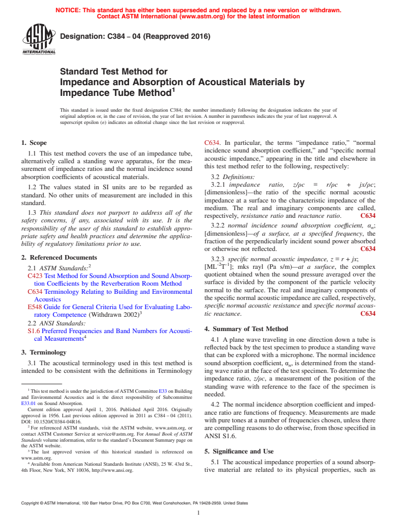
1.1 This test method covers the use of an impedance tube, alternatively called a standing wave apparatus, for the measurement of impedance ratios and the normal incidence sound absorption coefficients of acoustical materials.
1.2 The values stated in SI units are to be regarded as standard. No other units of measurement are included in this standard.
1.3 This standard does not purport to address all of the safety concerns, if any, associated with its use. It is the responsibility of the user of this standard to establish appropriate safety and health practices and determine the applicability of regulatory limitations prior to use.
General Information
Buy Standard
Standards Content (Sample)
NOTICE: This standard has either been superseded and replaced by a new version or withdrawn.
Contact ASTM International (www.astm.org) for the latest information
Designation: C384 − 04 (Reapproved 2016)
Standard Test Method for
Impedance and Absorption of Acoustical Materials by
Impedance Tube Method
This standard is issued under the fixed designation C384; the number immediately following the designation indicates the year of
original adoption or, in the case of revision, the year of last revision.Anumber in parentheses indicates the year of last reapproval.A
superscript epsilon (´) indicates an editorial change since the last revision or reapproval.
1. Scope C634. In particular, the terms “impedance ratio,” “normal
incidence sound absorption coefficient,” and “specific normal
1.1 This test method covers the use of an impedance tube,
acoustic impedance,” appearing in the title and elsewhere in
alternatively called a standing wave apparatus, for the mea-
this test method refer to the following, respectively:
surement of impedance ratios and the normal incidence sound
absorption coefficients of acoustical materials. 3.2 Definitions:
3.2.1 impedance ratio, z/ρc ≡ r/ρc + jx/ρc;
1.2 The values stated in SI units are to be regarded as
[dimensionless]—the ratio of the specific normal acoustic
standard. No other units of measurement are included in this
impedance at a surface to the characteristic impedance of the
standard.
medium. The real and imaginary components are called,
1.3 This standard does not purport to address all of the
respectively, resistance ratio and reactance ratio. C634
safety concerns, if any, associated with its use. It is the
3.2.2 normal incidence sound absorption coeffıcient, α ;
n
responsibility of the user of this standard to establish appro-
[dimensionless]—of a surface, at a specified frequency, the
priate safety and health practices and determine the applica-
fraction of the perpendicularly incident sound power absorbed
bility of regulatory limitations prior to use.
or otherwise not reflected. C634
2. Referenced Documents
3.2.3 specific normal acoustic impedance, z ≡r+jx;
-2 -1
[ML T ]; mks rayl (Pa s/m)—at a surface, the complex
2.1 ASTM Standards:
quotient obtained when the sound pressure averaged over the
C423TestMethodforSoundAbsorptionandSoundAbsorp-
surface is divided by the component of the particle velocity
tion Coefficients by the Reverberation Room Method
normal to the surface. The real and imaginary components of
C634Terminology Relating to Building and Environmental
thespecificnormalacousticimpedancearecalled,respectively,
Acoustics
specific normal acoustic resistance and specific normal acous-
E548Guide for General Criteria Used for Evaluating Labo-
tic reactance. C634
ratory Competence (Withdrawn 2002)
2.2 ANSI Standards:
4. Summary of Test Method
S1.6Preferred Frequencies and Band Numbers forAcousti-
cal Measurements
4.1 A plane wave traveling in one direction down a tube is
reflectedbackbythetestspecimentoproduceastandingwave
3. Terminology
that can be explored with a microphone.The normal incidence
3.1 The acoustical terminology used in this test method is sound absorption coefficient, α , is determined from the stand-
n
intended to be consistent with the definitions in Terminology ingwaveratioatthefaceofthetestspecimen.Todeterminethe
impedance ratio, z/ρc, a measurement of the position of the
standing wave with reference to the face of the specimen is
ThistestmethodisunderthejurisdictionofASTMCommitteeE33onBuilding
needed.
and Environmental Acoustics and is the direct responsibility of Subcommittee
E33.01 on Sound Absorption.
4.2 The normal incidence absorption coefficient and imped-
Current edition approved April 1, 2016. Published April 2016. Originally
ance ratio are functions of frequency. Measurements are made
approved in 1956. Last previous edition approved in 2011 as C384–04 (2011).
withpuretonesatanumberoffrequencieschosen,unlessthere
DOI: 10.1520/C0384-04R16.
For referenced ASTM standards, visit the ASTM website, www.astm.org, or
arecompellingreasonstodootherwise,fromthosespecifiedin
contact ASTM Customer Service at service@astm.org. For Annual Book of ASTM
ANSI S1.6.
Standards volume information, refer to the standard’s Document Summary page on
the ASTM website.
The last approved version of this historical standard is referenced on 5. Significance and Use
www.astm.org.
5.1 The acoustical impedance properties of a sound absorp-
Available fromAmerican National Standards Institute (ANSI), 25 W. 43rd St.,
4th Floor, New York, NY 10036, http://www.ansi.org. tive material are related to its physical properties, such as
Copyright © ASTM International, 100 Barr Harbor Drive, PO Box C700, West Conshohocken, PA 19428-2959. United States
C384 − 04 (2016)
airflowresistance,porosity,elasticity,anddensity.Assuch,the It is best to work well below these limits whether the tube is
measurements described in this test method are useful in basic circularorrectangular.Atfrequenciesabovetheselimits,cross
research and product development of sound absorptive mate- modesmaydevelopandtheincidentandreflectedwavesinthe
rials. tubearenotlikelytobeplanewaves.Ifsoundwithafrequency
below the limiting value enters the tube as a non-plane wave,
5.2 Normal incidence sound absorption coefficients are
itwillbecomeaplanewaveaftertravelingashortdistance.For
more useful than random incidence coefficients in certain
this reason, no measurement should be made closer than one
situations. They are used, for example, to predict the effect of
tube diameter to the source end of the tube.
placing material in a small enclosed space, such as inside a
6.1.1.3 Length—The length of the tube is also related to the
machine.
frequencies at which measurements are made. The tube must
5.3 Estimates of the random incidence or statistical absorp-
belongenoughtocontainthatpartofthestandingwavepattern
tion coefficients for materials can be obtained from normal
needed for measurement. That is, it must be long enough to
incidence impedance data. For materials that are locally
containatleastoneandpreferablytwosoundpressureminima.
reacting, that is, without sound propagation inside the material
Toensurethatatleasttwominimacanbeobservedinthetube,
parallel to its surface, statistical absorption coefficients can be
its length should be such that:
estimated from specific normal acoustic impedance values
5 f.0.75 c/ l 2 d (3)
~ !
using an expression derived by London (1). Locally reacting
materials include those with high internal losses parallel with
where:
the surface such as porous or fibrous materials of high density
l = length of tube, m.
or materials that are backed by partitioned cavities such as a
If, for example, the tube is1min length and 0.1 m in
honeycomb core. Formulas for estimating random incidence
diameter and the speed of sound is 343 m/s, the frequency
sound absorption properties for both locally and bulk-reacting
should exceed 286 Hz if two sound pressure minima are to be
materials, as well as for multilayer systems with and without
observed.
air spaces have also been developed (2).
6.1.2 Test Specimen Holder—The specimen holder, a de-
tachable extension of the tube, must make an airtight fit with
6. Apparatus
the end of the tube opposite the sound source. Provision must
6.1 The apparatus is essentially a tube with a test specimen
be made for containing the specimen with its face in a known
at one end and a loudspeaker at the other.Aprobe microphone
position. The interior cross-sectional shape of the specimen
that can be moved along the length of the tube is used to
holder must be the same as the tube itself. Provision must be
explore the standing wave in the tube. The signal from the
made for backing the specimen with a metal backing plate that
microphone is filtered, amplified, and recorded.
forms a seal with the interior of the specimen holder. A
6.1.1 Tube:
recommended backing is a solid steel plate with a thickness of
6.1.1.1 Construction—The tube may be made of metal,
not less than 2 cm. The sample holder may be constructed in
plastic, portland cement, or other suitable material that has
such a way that a variable depth air space can be provided
inherently low sound absorption properties. Its interior cross
between the back of the test specimen and the surface of the
section may be circular or rectangular but must be uniform
metal backing plate. Provision must be made for substituting
from end to end. The tube must be straight and its inside
the metal backing plate for the specimen for calibration
surfacemustbesmooth,nonporousandfreeofdusttokeepthe
purposes.
sound attenuation with distance low. The interior of the tube
6.1.3 Sound Source:
may be sealed with paint, epoxy, or other coating material to
6.1.3.1 Kind and Placement—The sound source may be a
ensure low sound absorption of the interior surface. The tube
loudspeaker or a horn-driver coupled to a short exponential
wallsmustbemassiveandrigidenoughsothatthepropagation
horn. The source may face directly into the tube or, to avoid
of sound energy through them by vibration is negligible.
interference with the probe microphone, it may be placed to
6.1.1.2 Diameter—For circular tubes, the upper limit (3) of
oneside.Sincethesourcediametermaybelargerthanthetube
frequency is:
diameter,itisbesttomountthesourceinanenclosuretowhich
f,0.586 c/d (1)
the tube is connected.
6.1.3.2 Precautions—Precautions should be taken to avoid
where:
direct transmission of vibration from the sound source to the
f = frequency, Hz,
probe microphone where it enters the tube or to the tube itself.
c = speed of sound in the tube, m/s, and
Such vibrational transmission will be evidenced by a smaller
d = diameter of tube, m.
standing wave ratio (higher normal incidence sound absorp-
For rectangular tubes, with d used as a symbol for the larger
tion) than would be expected for the material under test.
cross section dimension, the upper limit is:
Vibration isolation material, such as polymeric foam, may be
f,0.500 c/d (2)
placed between the sound source and tube or the microphone
probe, or both, to minimize this effect. Interaction between the
soundfieldwithinthetubeandtheloudspeakerdiaphragmmay
cause the frequency response of the loudspeaker to be nonlin-
Theboldfacenumbersinparenthesesrefertothelistofreferencesattheendof
this standard. ear. Although this has no effect on measurement accuracy, it
C384 − 04 (2016)
does require awkward changes in amplifier gain settings when 6.1.9 Monitoring Oscilloscope—While not required for any
switching between test frequencies. This effect can be mini- actual measurement purpose, it is recommended that an oscil-
mized by lining the interior of the tube near the sound source loscope be used to monitor both the voltage driving the sound
with a porous, absorbent material. source and the output of the amplifier. Observing the oscillo-
scope trace is useful in locating the exact position of pressure
6.1.4 Microphone—If the microphone is small enough, it
minima within the tube as well as in detecting distortion,
maybeplacedinsidetheimpedancetubeconnectedtoarodor
excess noise, and other possible problems in the voltage
otherdevicethatcanbeusedtomoveitalongthelengthofthe
signals.
tube. If the microphone is placed within the tube, the total
cross-sectional area of the microphone and microphone sup-
7. Sampling
ports shall be less than 5% of the total cross-sectional area of
thetube.Inmostapplications,themicrophoneisontheoutside
7.1 At least three specimens, preferably more if the sample
connected to a hollow probe tube that is inserted through the is not uniform, should be cut from the sample for the test.
source end of the apparatus and is aligned with the central axis
Whenthesamplehasasurfacethatisnotuniform(forexample
ofthetube.Inprinciple,thesensingelementofthemicrophone a fissured acoustical tile), each specimen should be chosen to
orofthemicrophoneprobemaybepositionedanywherewithin
include, in proper proportion, the different kinds of surfaces
thetubecross-sectionalarea.Inpractice,themicrophoneorthe
existing in the larger sample.
end of the probe tube must be supported by a spider or other
8. Test Specimen Preparation and Mounting
device to maintain its position on the central axis of the
impedance tube or at a constant distance from the central axis.
8.1 The measured impedance properties can be strongly
6.1.5 Microphone Position Indicator—Ascale shall be pro-
influenced by the specimen mounting conditions. Therefore,
vided to measure the position of the microphone with respect
the following guidelines for the preparation and mounting of
to the specimen face. It is not necessary that zero on the scale
specimens are provided.
correspondtothepositionofthespecimenface.Theresolution
8.2 The specimen must have the same shape and area as the
of this scale should be such that microphone position can be
tubecrosssection,neithermorenorless.Thespecimenmustfit
measured to the nearest 1.0 mm or, if a vernier is used, to the
snugly into the specimen holder, fitting not so tightly that it
nearest 0.1 mm.
bulgesinthecenter,norsolooselythatthereisaspacebetween
6.1.6 Test Signal:
its edge and the holder. Movement of the specimen as a whole
6.1.6.1 Frequency—The test signal shall be provided by a
and spaces between the specimen perimeter and sample holder
sinewaveoscillatorgeneratingapuretonechosenfromthelist
can result in anomalous values of normal incidence sound
of preferred band center frequencies listed in ANSI S1.6. The
absorption. Specimen movement can be minimized by the use
test frequency shall be controlled to within 61% during the
ofthin,double-sidedadhesivetapeappliedbetweenthebackof
course of a measurement. If a digital frequency synthesizer is
the specimen and the metal backing plate. Spaces at the
used,thetestsignalmaybeassumedtoagreewiththesetpoint
specimen perimeter can be sealed with petroleum jelly.
within the required 61%.
8.3 The specimen must have a relatively flat surface since
6.1.6.2 Frequency Counter—It may be necessary, and is
the reflected wave from a very uneven surface may not have
usually advisable, to measure the frequency of the signal with
become a plane wave at the position of the first minimum. If
an electronic counter rather than to rely on the calibration and
the specimen is an anechoic wedge, or an array of wedges,
indicated setting of the frequency generator. Frequency should
refer to Annex A1.
be indicated to the nearest 1 Hz.
8.4 When the specimen has a very uneven back, a layer of
6.1.7 Output-Measuring Equipment:
putty-like material should be placed between it and the metal
6.1.7.1 Filter—The microphone output should be filtered to
backing plate to seal the back of the specimen and to add
remove any harmonics and to reduce the adverse effect of
enough thickness to make the back of the specimen parallel to
ambientnoise.Thefilte
...
This document is not an ASTM standard and is intended only to provide the user of an ASTM standard an indication of what changes have been made to the previous version. Because
it may not be technically possible to adequately depict all changes accurately, ASTM recommends that users consult prior editions as appropriate. In all cases only the current version
of the standard as published by ASTM is to be considered the official document.
Designation: C384 − 04 (Reapproved 2011) C384 − 04 (Reapproved 2016)
Standard Test Method for
Impedance and Absorption of Acoustical Materials by
Impedance Tube Method
This standard is issued under the fixed designation C384; the number immediately following the designation indicates the year of
original adoption or, in the case of revision, the year of last revision. A number in parentheses indicates the year of last reapproval. A
superscript epsilon (´) indicates an editorial change since the last revision or reapproval.
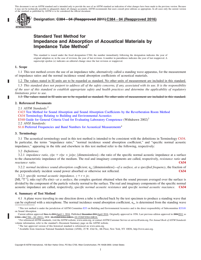
1. Scope
1.1 This test method covers the use of an impedance tube, alternatively called a standing wave apparatus, for the measurement
of impedance ratios and the normal incidence sound absorption coefficients of acoustical materials.
1.2 The values stated in SI units are to be regarded as standard. No other units of measurement are included in this standard.
1.3 This standard does not purport to address all of the safety concerns, if any, associated with its use. It is the responsibility
of the user of this standard to establish appropriate safety and health practices and determine the applicability of regulatory
limitations prior to use.
1.3 The values stated in SI units are to be regarded as standard. No other units of measurement are included in this standard.
2. Referenced Documents
2.1 ASTM Standards:
C423 Test Method for Sound Absorption and Sound Absorption Coefficients by the Reverberation Room Method
C634 Terminology Relating to Building and Environmental Acoustics
E548 Guide for General Criteria Used for Evaluating Laboratory Competence (Withdrawn 2002)
2.2 ANSI Standards:
S1.6 Preferred Frequencies and Band Numbers for Acoustical Measurements
3. Terminology
3.1 The acoustical terminology used in this test method is intended to be consistent with the definitions in Terminology C634.
In particular, the terms “impedance ratio,” “normal incidence sound absorption coefficient,” and “specific normal acoustic
impedance,” appearing in the title and elsewhere in this test method refer to the following, respectively:
3.2 Definitions:
3.2.1 impedance ratio, z/ρc ≡ r/ρc + jx/ρc; [dimensionless]—the ratio of the specific normal acoustic impedance at a surface
to the characteristic impedance of the medium. The real and imaginary components are called, respectively, resistance ratio and
reactance ratio. C634
3.2.2 normal incidence sound absorption coeffıcient, α ; [dimensionless]—of a surface, at a specified frequency, the fraction of
n
the perpendicularly incident sound power absorbed or otherwise not reflected. C634
3.2.3 specific normal acoustic impedance, z ≡ r + jx;
-2 -1
[ML T ]; mks rayl (Pa s/m)—at a surface, the complex quotient obtained when the sound pressure averaged over the surface is
divided by the component of the particle velocity normal to the surface. The real and imaginary components of the specific normal
acoustic impedance are called, respectively, specific normal acoustic resistance and specific normal acoustic reactance. C634
4. Summary of Test Method
4.1 A plane wave traveling in one direction down a tube is reflected back by the test specimen to produce a standing wave that
can be explored with a microphone. The normal incidence sound absorption coefficient, α , is determined from the standing wave
n
This test method is under the jurisdiction of ASTM Committee E33 on Building and Environmental Acoustics and is the direct responsibility of Subcommittee E33.01
on Sound Absorption.
Current edition approved Nov. 1, 2011April 1, 2016. Published December 2011April 2016. Originally approved in 1956. Last previous edition approved in 20042011 as
C384 – 04.C384 – 04 (2011). DOI: 10.1520/C0384-04R11. 10.1520/C0384-04R16.
For referenced ASTM standards, visit the ASTM website, www.astm.org, or contact ASTM Customer Service at service@astm.org. For Annual Book of ASTM Standards
volume information, refer to the standard’s Document Summary page on the ASTM website.
The last approved version of this historical standard is referenced on www.astm.org.
Available from American National Standards Institute (ANSI), 25 W. 43rd St., 4th Floor, New York, NY 10036, http://www.ansi.org.
Copyright © ASTM International, 100 Barr Harbor Drive, PO Box C700, West Conshohocken, PA 19428-2959. United States
C384 − 04 (2016)
ratio at the face of the test specimen. To determine the impedance ratio, z/ρc, a measurement of the position of the standing wave
with reference to the face of the specimen is needed.
4.2 The normal incidence absorption coefficient and impedance ratio are functions of frequency. Measurements are made with
pure tones at a number of frequencies chosen, unless there are compelling reasons to do otherwise, from those specified in ANSI
S1.6.
5. Significance and Use
5.1 The acoustical impedance properties of a sound absorptive material are related to its physical properties, such as airflow
resistance, porosity, elasticity, and density. As such, the measurements described in this test method are useful in basic research
and product development of sound absorptive materials.
5.2 Normal incidence sound absorption coefficients are more useful than random incidence coefficients in certain situations.
They are used, for example, to predict the effect of placing material in a small enclosed space, such as inside a machine.
5.3 Estimates of the random incidence or statistical absorption coefficients for materials can be obtained from normal incidence
impedance data. For materials that are locally reacting, that is, without sound propagation inside the material parallel to its surface,
statistical absorption coefficients can be estimated from specific normal acoustic impedance values using an expression derived by
London (1). Locally reacting materials include those with high internal losses parallel with the surface such as porous or fibrous
materials of high density or materials that are backed by partitioned cavities such as a honeycomb core. Formulas for estimating
random incidence sound absorption properties for both locally and bulk-reacting materials, as well as for multilayer systems with
and without air spaces have also been developed (2).
6. Apparatus
6.1 The apparatus is essentially a tube with a test specimen at one end and a loudspeaker at the other. A probe microphone that
can be moved along the length of the tube is used to explore the standing wave in the tube. The signal from the microphone is
filtered, amplified, and recorded.
6.1.1 Tube:
6.1.1.1 Construction—The tube may be made of metal, plastic, portland cement, or other suitable material that has inherently
low sound absorption properties. Its interior cross section may be circular or rectangular but must be uniform from end to end. The
tube must be straight and its inside surface must be smooth, nonporous and free of dust to keep the sound attenuation with distance
low. The interior of the tube may be sealed with paint, epoxy, or other coating material to ensure low sound absorption of the
interior surface. The tube walls must be massive and rigid enough so that the propagation of sound energy through them by
vibration is negligible.
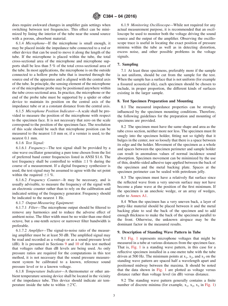
6.1.1.2 Diameter—For circular tubes, the upper limit (3) of frequency is:
f,0.586 c/d (1)
where:
f = frequency, Hz,
c = speed of sound in the tube, m/s, and
d = diameter of tube, m.
For rectangular tubes, with d used as a symbol for the larger cross section dimension, the upper limit is:
f,0.500 c/d (2)
It is best to work well below these limits whether the tube is circular or rectangular. At frequencies above these limits, cross
modes may develop and the incident and reflected waves in the tube are not likely to be plane waves. If sound with a frequency
below the limiting value enters the tube as a non-plane wave, it will become a plane wave after traveling a short distance. For this
reason, no measurement should be made closer than one tube diameter to the source end of the tube.
6.1.1.3 Length—The length of the tube is also related to the frequencies at which measurements are made. The tube must be
long enough to contain that part of the standing wave pattern needed for measurement. That is, it must be long enough to contain
at least one and preferably two sound pressure minima. To ensure that at least two minima can be observed in the tube, its length
should be such that:
f.0.75 c/ l 2 d (3)
~ !
where:
l = length of tube, m.
If, for example, the tube is 1 m in length and 0.1 m in diameter and the speed of sound is 343 m/s, the frequency should exceed
286 Hz if two sound pressure minima are to be observed.
The boldface numbers in parentheses refer to the list of references at the end of this standard.
C384 − 04 (2016)
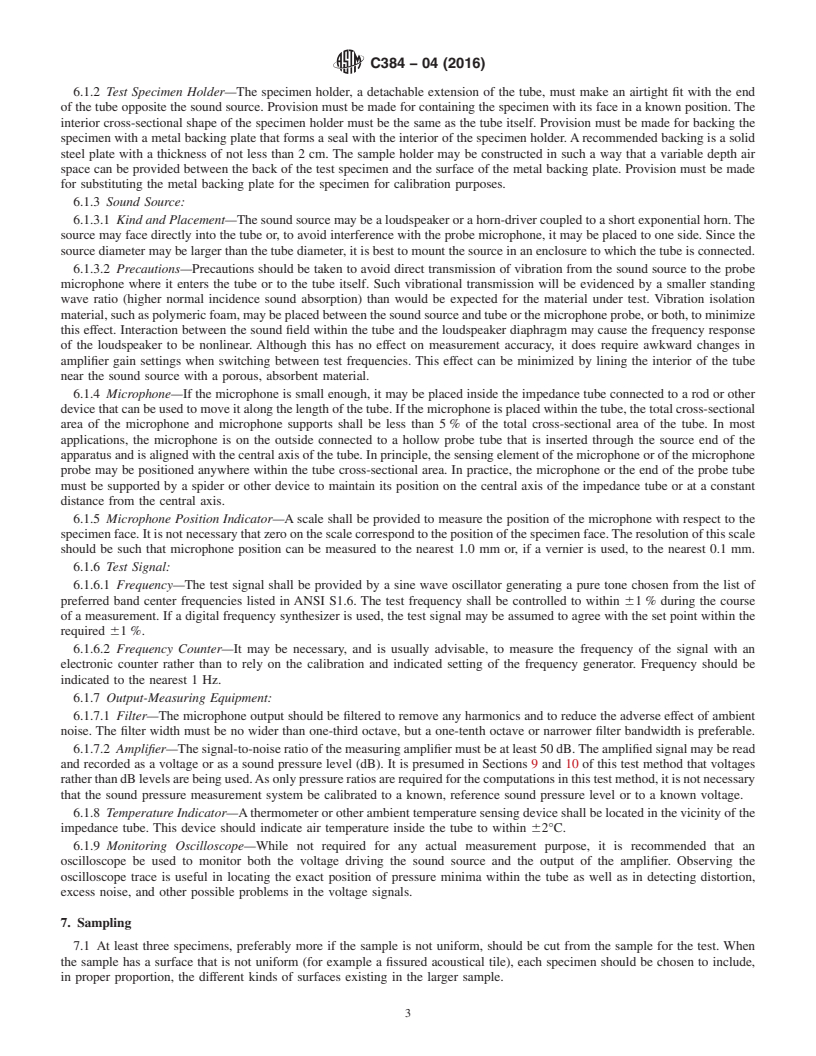
6.1.2 Test Specimen Holder—The specimen holder, a detachable extension of the tube, must make an airtight fit with the end
of the tube opposite the sound source. Provision must be made for containing the specimen with its face in a known position. The
interior cross-sectional shape of the specimen holder must be the same as the tube itself. Provision must be made for backing the
specimen with a metal backing plate that forms a seal with the interior of the specimen holder. A recommended backing is a solid
steel plate with a thickness of not less than 2 cm. The sample holder may be constructed in such a way that a variable depth air
space can be provided between the back of the test specimen and the surface of the metal backing plate. Provision must be made
for substituting the metal backing plate for the specimen for calibration purposes.
6.1.3 Sound Source:
6.1.3.1 Kind and Placement—The sound source may be a loudspeaker or a horn-driver coupled to a short exponential horn. The
source may face directly into the tube or, to avoid interference with the probe microphone, it may be placed to one side. Since the
source diameter may be larger than the tube diameter, it is best to mount the source in an enclosure to which the tube is connected.
6.1.3.2 Precautions—Precautions should be taken to avoid direct transmission of vibration from the sound source to the probe
microphone where it enters the tube or to the tube itself. Such vibrational transmission will be evidenced by a smaller standing
wave ratio (higher normal incidence sound absorption) than would be expected for the material under test. Vibration isolation
material, such as polymeric foam, may be placed between the sound source and tube or the microphone probe, or both, to minimize
this effect. Interaction between the sound field within the tube and the loudspeaker diaphragm may cause the frequency response
of the loudspeaker to be nonlinear. Although this has no effect on measurement accuracy, it does require awkward changes in
amplifier gain settings when switching between test frequencies. This effect can be minimized by lining the interior of the tube
near the sound source with a porous, absorbent material.
6.1.4 Microphone—If the microphone is small enough, it may be placed inside the impedance tube connected to a rod or other
device that can be used to move it along the length of the tube. If the microphone is placed within the tube, the total cross-sectional
area of the microphone and microphone supports shall be less than 5 % of the total cross-sectional area of the tube. In most
applications, the microphone is on the outside connected to a hollow probe tube that is inserted through the source end of the
apparatus and is aligned with the central axis of the tube. In principle, the sensing element of the microphone or of the microphone
probe may be positioned anywhere within the tube cross-sectional area. In practice, the microphone or the end of the probe tube
must be supported by a spider or other device to maintain its position on the central axis of the impedance tube or at a constant
distance from the central axis.
6.1.5 Microphone Position Indicator—A scale shall be provided to measure the position of the microphone with respect to the
specimen face. It is not necessary that zero on the scale correspond to the position of the specimen face. The resolution of this scale
should be such that microphone position can be measured to the nearest 1.0 mm or, if a vernier is used, to the nearest 0.1 mm.
6.1.6 Test Signal:
6.1.6.1 Frequency—The test signal shall be provided by a sine wave oscillator generating a pure tone chosen from the list of
preferred band center frequencies listed in ANSI S1.6. The test frequency shall be controlled to within 61 % during the course
of a measurement. If a digital frequency synthesizer is used, the test signal may be assumed to agree with the set point within the
required 61 %.
6.1.6.2 Frequency Counter—It may be necessary, and is usually advisable, to measure the frequency of the signal with an
electronic counter rather than to rely on the calibration and indicated setting of the frequency generator. Frequency should be
indicated to the nearest 1 Hz.
6.1.7 Output-Measuring Equipment:
6.1.7.1 Filter—The microphone output should be filtered to remove any harmonics and to reduce the adverse effect of ambient
noise. The filter width must be no wider than one-third octave, but a one-tenth octave or narrower filter bandwidth is preferable.
6.1.7.2 Amplifier—The signal-to-noise ratio of the measuring amplifier must be at least 50 dB. The amplified signal may be read
and recorded as a voltage or as a sound pressure level (dB). It is presumed in Sections 9 and 10 of this test method that voltages
rather than dB levels are being used. As only pressure ratios are required for the computations in this test method, it is not necessary
that the sound pressure measurement system be calibrated to a known, reference sound pressure level or to a known voltage.
6.1.8 Temperature Indicator—A thermometer or other ambient temperature sensing device shall be located in the vicinity of the
impedance tube. This device should indicate air temperature inside the tube to within 62°C.
6.1.9 Monitoring Oscilloscope—While not required for any actual measurement purpose, it is recommended that an
oscilloscope be used to monitor both the voltage driving the sound source and the output of the amplifier. Observing the
oscilloscope trace is useful in locating the exact position of pressure minima within the tube as well as in detecting distortion,
excess noise, and other possible problems in the voltage signals.
7. Sampling
7.1 At least three specimens, preferably more if the s
...
Questions, Comments and Discussion
Ask us and Technical Secretary will try to provide an answer. You can facilitate discussion about the standard in here.