

ASTM F3283/F3283M-18
(Specification)Standard Specification for the Manufacturing of High-Voltage Proximity Alarm to be used for the Detection of Overhead High Voltage Alternating Current (AC)
General Information
- Abstract
SCOPE
1.1 This specification covers non-contact high-voltage proximity alarms used to detect high voltage alternating current (ac) on overhead power lines. The high-voltage proximity alarm (HVPA) is limited to the detection of voltage greater than 600 V ac at power system frequencies between 50 to 60 Hz.
1.2 High-voltage proximity alarms provide audible/visual alerts and may have the ability to limit movement of equipment.
1.3 The use, installation, and maintenance of these high-voltage proximity alarms are beyond the scope of this specification. This standard does not purport to address installation, in service care or use.
1.4 This standard demonstrates the high voltage proximity alarm (HVPA’s) ability to detect an e-field, and not the effects of various configurations of multiple power lines.
1.5 The values stated in either SI units or inch-pound units are to be regarded separately as standard. The values stated in each system are not necessarily exact equivalents; therefore, to ensure conformance with the standard, each system shall be used independently of the other, and values from the two systems shall not be combined.
1.6 This standard does not purport to address all of the safety concerns, if any, associated with its use. It is the responsibility of the user of this standard to establish appropriate safety, health, and environmental practices and determine the applicability of regulatory limitations prior to use. Specific warnings are given in 9.1.4 and 10.9.2.
1.7 This international standard was developed in accordance with internationally recognized principles on standardization established in the Decision on Principles for the Development of International Standards, Guides and Recommendations issued by the World Trade Organization Technical Barriers to Trade (TBT) Committee.
- Status
- Published
- Publication Date
- 30-Sep-2018
- Technical Committee
- F18 - Electrical Protective Equipment for Workers
- Drafting Committee
- F18.35 - Tools & Equipment
Overview
ASTM F3283/F3283M-18 specifies requirements for manufacturing non-contact high-voltage proximity alarms (HVPA) used for detecting overhead high voltage alternating current (AC) power lines. The scope of this standard covers alarms capable of identifying voltages greater than 600 V AC at frequencies between 50 Hz and 60 Hz. These proximity alarms are designed to protect personnel and equipment by providing audible and/or visual warnings when nearing energized overhead power lines.
High-voltage proximity alarms play a critical role in improving safety on job sites by helping operators and ground personnel avoid accidental contact with hazardous voltages. This standard governs the manufacturing and testing of these alarms but does not address their installation or maintenance in the field.
Key Topics
- High-voltage detection: The HVPA must detect the e-field associated with overhead AC power lines over 600 V and provide reliable warnings.
- Warning indications: Devices must include both audible and visual alarm signals to alert users to dangerous proximity conditions. Some alarms may also limit equipment movement (function kick out system).
- Performance requirements: The manufacturer must clearly specify operating voltage, temperature and humidity range, limitations, and e-field detection range. Devices must withstand various environmental conditions and maintain effective performance.
- Testing protocols: The standard outlines rigorous test scenarios, including saturation tests, shadowing effects, typical and possible operating scenarios, and variable equipment configurations.
- Workmanship and durability: Devices must be constructed with high-quality, impact-resistant materials and labeled with essential operating information.
- Audible and visual thresholds: Defined minimum decibel outputs and visual indicators ensure alarm effectiveness in various environments.
Applications
- Construction and utility operations: HVPA devices are widely used where cranes, booms, or other equipment operate near overhead power lines, providing essential warnings to prevent electrical accidents.
- Electrical maintenance: Field teams working around live conductors benefit from these alarms, which supplement traditional safety practices by adding an additional non-contact warning layer.
- Industrial and mining sectors: Any industry using tall mobile equipment in environments with exposed AC power lines can utilize these devices to improve worker safety.
- Rental equipment compliance: Equipment manufacturers and rental agencies adopt this standard to ensure their products meet recognized safety benchmarks before deployment.
Related Standards
- ASTM F855: Standard Specifications for Temporary Protective Grounds to Be Used on De-energized Electric Power Lines and Equipment.
- ASTM F1506: Standard Performance Specification for Flame Resistant and Electric Arc Rated Protective Clothing.
- ANSI/IEEE C37.20.2: Standard for Metal-Clad Switchgear.
- OSHA regulations: Guidelines addressing work near electrical hazards often reference or require compliant proximity alarm usage.
- IEC 60204-1: International standard relating to the safety of electrical equipment of machines, relevant for global harmonization.
Practical Value
Adhering to ASTM F3283/F3283M-18 ensures that high-voltage proximity alarms provide consistent, reliable protection against accidental electrical contact. By following this standard, manufacturers demonstrate a commitment to workforce safety, regulatory compliance, and product reliability. The standard's robust testing and documentation requirements foster confidence for employers, equipment operators, and regulatory bodies, ultimately reducing workplace injuries and liability concerns.
Keywords: ASTM F3283, high-voltage proximity alarm, non-contact detection, overhead power lines, AC voltage safety, audible visual warning, electrical safety standards, e-field detection, workplace safety, equipment manufacturing compliance.
Get Certified
Connect with accredited certification bodies for this standard

CIS Institut d.o.o.
Personal Protective Equipment (PPE) certification body. Notified Body NB-2890 for EU Regulation 2016/425 PPE.

Kiwa BDA Testing
Building and construction product certification.
Kmetijski inštitut Slovenije
Agricultural Institute of Slovenia. Soil testing, plant health, agricultural product analysis.
Sponsored listings
Frequently Asked Questions
ASTM F3283/F3283M-18 is a technical specification published by ASTM International. Its full title is "Standard Specification for the Manufacturing of High-Voltage Proximity Alarm to be used for the Detection of Overhead High Voltage Alternating Current (AC)". This standard covers: SCOPE 1.1 This specification covers non-contact high-voltage proximity alarms used to detect high voltage alternating current (ac) on overhead power lines. The high-voltage proximity alarm (HVPA) is limited to the detection of voltage greater than 600 V ac at power system frequencies between 50 to 60 Hz. 1.2 High-voltage proximity alarms provide audible/visual alerts and may have the ability to limit movement of equipment. 1.3 The use, installation, and maintenance of these high-voltage proximity alarms are beyond the scope of this specification. This standard does not purport to address installation, in service care or use. 1.4 This standard demonstrates the high voltage proximity alarm (HVPA’s) ability to detect an e-field, and not the effects of various configurations of multiple power lines. 1.5 The values stated in either SI units or inch-pound units are to be regarded separately as standard. The values stated in each system are not necessarily exact equivalents; therefore, to ensure conformance with the standard, each system shall be used independently of the other, and values from the two systems shall not be combined. 1.6 This standard does not purport to address all of the safety concerns, if any, associated with its use. It is the responsibility of the user of this standard to establish appropriate safety, health, and environmental practices and determine the applicability of regulatory limitations prior to use. Specific warnings are given in 9.1.4 and 10.9.2. 1.7 This international standard was developed in accordance with internationally recognized principles on standardization established in the Decision on Principles for the Development of International Standards, Guides and Recommendations issued by the World Trade Organization Technical Barriers to Trade (TBT) Committee.
SCOPE 1.1 This specification covers non-contact high-voltage proximity alarms used to detect high voltage alternating current (ac) on overhead power lines. The high-voltage proximity alarm (HVPA) is limited to the detection of voltage greater than 600 V ac at power system frequencies between 50 to 60 Hz. 1.2 High-voltage proximity alarms provide audible/visual alerts and may have the ability to limit movement of equipment. 1.3 The use, installation, and maintenance of these high-voltage proximity alarms are beyond the scope of this specification. This standard does not purport to address installation, in service care or use. 1.4 This standard demonstrates the high voltage proximity alarm (HVPA’s) ability to detect an e-field, and not the effects of various configurations of multiple power lines. 1.5 The values stated in either SI units or inch-pound units are to be regarded separately as standard. The values stated in each system are not necessarily exact equivalents; therefore, to ensure conformance with the standard, each system shall be used independently of the other, and values from the two systems shall not be combined. 1.6 This standard does not purport to address all of the safety concerns, if any, associated with its use. It is the responsibility of the user of this standard to establish appropriate safety, health, and environmental practices and determine the applicability of regulatory limitations prior to use. Specific warnings are given in 9.1.4 and 10.9.2. 1.7 This international standard was developed in accordance with internationally recognized principles on standardization established in the Decision on Principles for the Development of International Standards, Guides and Recommendations issued by the World Trade Organization Technical Barriers to Trade (TBT) Committee.
ASTM F3283/F3283M-18 is classified under the following ICS (International Classification for Standards) categories: 13.260 - Protection against electric shock. Live working. The ICS classification helps identify the subject area and facilitates finding related standards.
ASTM F3283/F3283M-18 is available in PDF format for immediate download after purchase. The document can be added to your cart and obtained through the secure checkout process. Digital delivery ensures instant access to the complete standard document.
Standards Content (Sample)
This international standard was developed in accordance with internationally recognized principles on standardization established in the Decision on Principles for the
Development of International Standards, Guides and Recommendations issued by the World Trade Organization Technical Barriers to Trade (TBT) Committee.
Designation:F3283/F3283M −18
Standard Specification for
the Manufacturing of High-Voltage Proximity Alarm to be
used for the Detection of Overhead High Voltage Alternating
Current (AC)
ThisstandardisissuedunderthefixeddesignationF3283/F3283M;thenumberimmediatelyfollowingthedesignationindicatestheyear
of original adoption or, in the case of revision, the year of last revision. A number in parentheses indicates the year of last reapproval.
A superscript epsilon (´) indicates an editorial change since the last revision or reapproval.
1. Scope 2. Terminology
1.1 Thisspecificationcoversnon-contacthigh-voltageprox- 2.1 Definitions:
imityalarmsusedtodetecthighvoltagealternatingcurrent(ac) 2.1.1 alternating current (ac) voltage, n—potential differ-
on overhead power lines. The high-voltage proximity alarm ence in charge between two connected points in which the
(HVPA) is limited to the detection of voltage greater than 600 direction of current flow alternates.
V ac at power system frequencies between 50 to 60 Hz.
2.1.2 audible alarm indication, n—audible alarm that is
initiated when a predetermined threshold is met.
1.2 High-voltage proximity alarms provide audible/visual
alerts and may have the ability to limit movement of equip-
2.1.3 configuration, n—closely coupled and non-closely
ment.
coupled equipment. For example, outriggers or steel treads for
closely coupled equipment, and rubber tires for non-closely
1.3 The use, installation, and maintenance of these high-
coupled as specified by the HVPA manufacturer. Specifically
voltage proximity alarms are beyond the scope of this specifi-
excludes equipment intended to work closer than 10 ft to an
cation.Thisstandarddoesnotpurporttoaddressinstallation,in
overhead ac power line.
service care or use.
2.1.4 direct current (dc) voltage, n—potential difference in
1.4 This standard demonstrates the high voltage proximity
charge between two connected points in which the direction of
alarm (HVPA’s) ability to detect an e-field, and not the effects
current flow does not change.
of various configurations of multiple power lines.
2.1.5 E-field, n—electric force per unit change.
1.5 The values stated in either SI units or inch-pound units
2.1.6 equipment, n—specific types of equipment that the
are to be regarded separately as standard. The values stated in
manufacturer endorses.
each system are not necessarily exact equivalents; therefore, to
ensure conformance with the standard, each system shall be
2.1.7 function kick out system (optional), n—system by
used independently of the other, and values from the two
which the equipment operated is being forcibly shut down by
systems shall not be combined.
the high-voltage proximity alarm, also known as auto-
shutdown.
1.6 This standard does not purport to address all of the
safety concerns, if any, associated with its use. It is the
2.1.8 high voltage, n—any measured voltage higher than
responsibility of the user of this standard to establish appro-
600 V ac.
priate safety, health, and environmental practices and deter-
2.1.9 high voltage proximity alarm, n—device that provides
mine the applicability of regulatory limitations prior to use.
a warning of general proximity to a power line also referred to
Specific warnings are given in 9.1.4 and 10.9.2.
as HVPA for proximity warning device.
1.7 This international standard was developed in accor-
2.1.10 information screen, n—panel area, in which images,
dance with internationally recognized principles on standard-
data, or both, are displayed to the operator.
ization established in the Decision on Principles for the
Development of International Standards, Guides and Recom- 2.1.11 limitation, n—threshold, parameters on both at which
mendations issued by the World Trade Organization Technical the high-voltage proximity alarm will not reliably function
Barriers to Trade (TBT) Committee. above or below, or both.
2.1.12 operational check, n—physical verification of com-
ponents to be used in conjunction with a self-test function.
This specification is under the jurisdiction of ASTM Committee F18 on
Electrical Protective Equipment for Workers and is the direct responsibility of
2.1.13 performance test, n—specific to type of equipment
Subcommittee F18.35 on Tools & Equipment.
endorsed by the manufacturer and should follow appropriate
Current edition approved Oct. 1, 2018. Published January 2019. DOI: 10.1520/
F3283_F3283M-18. manual instructions.
Copyright © ASTM International, 100 Barr Harbor Drive, PO Box C700, West Conshohocken, PA 19428-2959. United States
F3283/F3283M−18
2.1.14 power line, n—cable or coductor carrying electrical to the proximity of an energized conductor based on the
power typically supported by pylon or poles. minimum rating of the manufacturer’s equipment. This testing
scenario is meant to create a repeatable E-field for testing
2.1.15 range control, n—abilityofanoperatortomodifythe
purposes only.This controlled E-field environment also gives a
threshold settings of a high voltage proximity alarm.
corresponding benchmark for the test distance as shown in
2.1.16 self-test function, n—manual or automatic verifica-
8.1.1. The test does not cover the distance that can be achieved
tion process, or both, by the high voltage proximity alarm.
for various environmental factors.
2.1.17 sensor, n—devicethatisusedtodetectthestrengthof
8.1.1 Calculation for the Test Distance Required for Alarm
an E-field.
Activation—This testing scenario is meant to create a repeat-
2.1.18 SPF, n—Spruce/Pine/Fir. able E-field for testing purposes.
2.1.19 threshold, n—point at which, based on E-field TV 3 MC
TD 5 (1)
strength, the high-voltage alarm will enter into an alarm state. V
2.1.19.1 Discussion—This point may or may not be modi-
where:
fiable by the operator.
MC = minimum clearance = 10 ft.
2.1.20 visual alarm indication, n—sequence of flashing or
V = nominal voltage of overhead power line (based on
solid light(s), or both, that notify an operator or ground
manufacturer’s minimum equipment rating, with con-
personnel, or both, of current conditions/status.
sideration from 6.1.1).
TV = actual test voltage (the voltage used by the testing
3. Significance and Use
agencies). The test voltage range must be between 50
3.1 This manufacturing specification establishes require-
to100%ofthemanufacturer’svoltagerating(V)with
ments for the testing of HVPA used to alert operators and
an absolute minimum of 2000V. If the manufacturer’s
ground personnel of the general proximity to an overhead
rating is below 2000 V then the TV must be set at the
energized conductor with non-contacting methods.
minimum rated voltage specified by the manufacturer.
Test voltage tolerance of 62%.
4. Type of High-Voltage Proximity Alarm
TD = test distance (radial distance).
4.1 E-field detection. NOTE 1—MC and TD have the same unit of measure.
8.1.1.1 The following example illustrates the required test
5. Material
distance from which the high voltage proximity alarm thresh-
5.1 Control box should be made from impact-resistant
old is reached.
material and be free of defects that might adversely affect the MC=10ft
unit’s mechanical and electrical properties. The alarm system
V = 7.2 kV (voltage based on manufacturer’s minimum
being tested will differ dependent upon the manufacturer of the equipment rating).
product.
TV = 4.4 kV (voltage use by the testing agencies due to
capacity and availability).
6. Performance Requirements
~4.4 kV!~10 ft!
TD =
7.2 kV
6.1 The manufacturer shall clearly specify the limits of
TD = 6.1 ft = 73.3 in. (radial distance).
performance of each high voltage proximity alarm within the
8.1.1.2 6.1 ft (TD) is the theoretical distance at which the
instructions as follows:
6.1.1 Operating voltage range or ranges, high voltage proximity alarm threshold is reached based on the
manufacturer’s minimum equipment rating and TV used. The
6.1.2 Operating temperature range,
6.1.3 Operating humidity range, “test pass” is if the alarm provides a visual and audio warning.
8.1.2 Calculation for Horizontal Distance from the Test
6.1.4 Storage temperature range,
Distance—The radial distance for the E-field as illustrated in
6.1.5 Storage humidity range,
Fig. 1. The Pythagorean theorem can be used to derive the
6.1.6 Any limitations of use,
horizontal distance to the overhead power line as denoted with
6.1.7 E-field detection range,
x.
6.1.8 Applicable equipment approved by the manufacturer.
2 2 2
TD 5 x 15 (2)
7. Workmanship, Finish, and Appearance
2 2
x 5 =TD 2 5 (3)
7.1 Workmanship and finish shall be of such quality as to
ensure safe operation of the unit. Appearance shall be the
8.1.2.1 The following example illustrates the horizontal
prerogative of the manufacturer.
distance the high voltage proximity alarm must activate.
2 2 2
12.22 5 x 1 5 (4)
Test Methods
where:
2 2
x =
=TD 25
8. Testing Scenario and Rationale
2 2
x =
=12.22 25
8.1 Demonstrate that the high voltage proximity alarm
x = 11.2 ft
meets the requirements of providing visual and audio warning
F3283/F3283M−18
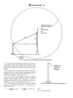
FIG. 1Illustration of Horizontal Distance Taken from Test Distance
8.1.2.2 Instead of measuring the test distance for each test,
a test distance guide (for example String) attached to the
overhead power line can be used for the series of tests. This
will aid the testing distances due to the spherical nature of the
E-field.
8.1.2.3 This series of tests uses the boom’s closest top
corner for reference, as such all high voltage proximity alarms
would be tested to the same reference disregarding the size of
the boom or equipment, or both. (See Fig. 2.)
8.1.3 Eq 1 in 8.1.1 will provide a ratio of minimum
clearance from the nominal voltage of powerline, minimum
clearance, and test voltage. This will serve as a proof of
concept that the HVPA will detect an E-field or voltage and
therefore the presence of an overhead ac power line.
8.1.4 The saturation test is based on a 32 800 V/m [10 0000
FIG. 2Testing Reference Point for Boom Apparatus
V/ft] and the saturation test distance is calculated by the
following equation:
1 1
SD 5 TV for metric, 5 TV for US customary where:
S D S D
32,800 10,000
SD = saturated distance.
(5)
F3283/F3283M−18
8.1.4.1 The saturation test distance is the HVPA’s distance while raising the boom apparatus up witha2by4SPF
away from the test power line that will ensure the HVPA will simulates a non-closely coupled scenario. (See Fig. 5.)
be fully saturated within the electrical field. For example, the
8.5 Saturation Rationale:
following example illustrates the use of Eq 5.
8.5.1 This verifies that saturation of the high voltage prox-
TV = 4.4 kV (voltage used by the testing agencies due to
imity alarm will not impair the ability of the device to meet the
capacity and availability.
requirements of the standard. (See Fig. 6.)
m ft
SD = 4.4 kV or 4.4 kV
S D S D
8.5.2 Position the 5 ft. boom apparatus at saturation test
32.8 kV 10.0 kV
distance (calculated in 8.1.4) away from the overhead power
SD = 0.134 m = 0.4 ft
line at 5 ft. line height. Energize the test overhead power for 10
8.1.4.2 With the test voltage of 4.4 kV, the required satura-
s, then de-energize the overhead power. Two iterations of
tion test distance would be 5.28 in. to ensure the HVPA is in
saturation tests are done at the mid span For in-depth
full saturation for testing purposes.
procedure, see 10.10.
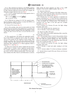
8.2 General Test Layout (Fig. 3):
8.5.3 Condition for Passing—To pass, the high voltage
proximity alarm must:
NOTE 2—The proximity alarm must be tested outside the E-field
generated by the test transformer with an additional 50 % test distance and
8.5.3.1 Be operated after the saturation test.
the high voltage line between the insulated power line apparatus and the
8.5.3.2 Provide a visual and audio warning.
test transformer should be insulated with metal liquid tight or metal
conduit. The radius of the No Test Zone is one and a half times the test
8.6 Shadowing Effect Rationale:
distance.
8.6.1 This verifies the possible shadowing effect caused by
r 5 1.5TD (6) the position of the boom.
8.6.2 The proximity alarm is tested at four positions shown
8.3 The manufacturer will indicate the applicable installa-
in Fig. 7 using the 5 ft boom apparatus at 5 ft of line height.
tion of their HVPA on equipment and its setup. Test agencies
This will verify the general working area 360° around the
will use this position for the majority of their testing. (This
boom in consideration to possible shadowing effect from the
attempts to reduce bias from using the optimal position for
boom. For in-depth procedure, see 10.11.
testing.) While the other positions will be tested for possible
8.6.3 Condition for passing—To pass, the high voltage
shadowing effect explained in 8.6. Boom apparatus detail is
proximity alarm must:
found in 9.1.5. ( See Fig. 4.)
8.6.3.1 Provide a visual and audio warning in all four
8.4 Most tests include the closely coupled and non-closely
positions.
coupled trials to simulate various equipment ground planes.
8.6.3.2 Activate within2%ofthe test distance calculated.
For example, equipment on tires and equipment with outrig-
gers down will have different ground plane. The boom appa- 8.7 Variable Boom Length (Telescopic Boom) and Antenna
ratus simulates this effect from its steel fabrication to concrete, Length Rationale:
FIG. 3General Test Layout
F3283/F3283M−18
FIG. 4Typical Installation to Boom and Installation to Boom Apparatus
8.8.3.1 Have two distinctly different modes of alarm, pro-
viding at least two of the following: visual, audible, or function
kick out system for closely coupled and non-closely coupled
boom apparatus.
8.8.3.2 Activate within2%ofthe test distance calculated.
8.9 Possible Operating Scenario:
8.9.1 This verifies the high voltage proximity alarm acti-
vates with possible electrical field deflection from the test
electrical post.
8.9.2 Approach the power line perpendicular to the post No.
2 (see Fig. 11). Test the deflection of the E-field due to the
proximity of the test electrical post. Post #2 is chosen for
testing due to it simulating a realistic scenario for equipment.
FIG. 5Closely Coupled and Non-closely Coupled Trials
The alarm system is tested at line height and half line height,
double the line height, and the proximity alarm system is
recalibrated for the three different test levels. For in-depth
8.7.1 This determines if the variable boom and antenna
procedure see 10.14.
length has detrimental effects on E-field detection. The mea-
8.9.3 Condition for Passing—To pass, the high voltage
sured E-field is expected to be different.
proximity alarm must:
8.7.2 The proximity alarm is tested at four positions as
8.9.3.1 Have two distinctly different modes of alarm, pro-
shown in 8.6, while using the 10 ft boom apparatus at 10 ft of
viding at least two of the following: visual, audible, or function
line height. For in-depth procedure see 10.12.
kick out system for closely coupled and non-closely coupled
NOTE 3—Depending on the testing facility, there may be degradation to
boom apparatus.
the E-field due to the ground plane as shown from the hatched area in Fig.
8.9.3.2 Activate within2%ofthe test distance calculated.
9.ThedegradationwouldreducethesizeoftheE-field.RefertoFig.8and
Fig. 9.
9. Apparatus
8.7.3 Condition for Passing—To pass, the high voltage
9.1 List of Test Laboratory Apparatus—The testing appara-
proximity alarm must:
tus suggested are used for scaled testing. If the testing facility
8.7.3.1 Provide a visual and audio warning in all four
has the capacity, the apparatus could be altered to better
positions.
simulate actual overhead power line scenarios with consider-
8.7.3.2 Activate within2%ofthe test distance calculated.
ations from 9.1.9.
8.8 Typical Operating Scenario:
8.8.1 This verifies the high voltage proximity alarm acti-
vates for typical operating scenario. Apparatus Quantity
High voltage proximity alarm 1
8.8.2 Approach the power line at mid-span between post
Test electrical posts 3
No. 1 and 2 (see Fig. 10).At mid-span, the E-field has minimal
Transformer stand 1
Screws as required
deflection and this testing scenario can serve as the verification
Insulated power line apparatus 1
to the test distance calculated in Eq 1 in 8.1.1. The alarm
5 ft boom apparatus 1
system is tested at line height and half line height, double the
10 ft boom apparatus 1
line height, and the proximity alarm system is recalibrated for Test distance guide as required
Transformer 1
the three different test levels. For in-depth procedure, see
Measuring tape 1
10.13.
Liquid tight (metal) or metal conduit as required
8.8.3 Condition for Passing—To pass, the high voltage
Dimensional tolerance: 62%.
proximity alarm must:
F3283/F3283M−18
FIG. 6Layout used for Saturation Test
FIG. 7Four Positions for Testing Shadowing Effects
FIG. 9Degradation to E-field Due to Ceiling
9.1.3 Test Transformer Stand, made form SPF (spruce, pine,
orfir)andasturdysupportbasetoensurestabilityofthetesting
apparatus. Other equipment may be used to replace the typical
test transformer stand ensuring the transformer is isolated from
the ground plane. (See Fig. 13.)
9.1.4 Insulated Power Line Apparatus consisting of:
(a) 28 ft of 600 V awg insulated wire (7 strand
recommended).Warning—Voltage rating of the wire is below
the test voltage and may cause electrical shock.
(b) 22 ft of 1 in. PVC tubing.
(c) PVC joiner.
(d) Plastic end cap.
FIG. 8Degradation to Electrical Due to Ground
(e) Plastic strain relief.
(f) Pressure connector.
9.1.1 High Voltage Proximity Alarms being tested will (g) PVC glue.
indicate the information differently dependent upon the manu- 9.1.4.1 Duetoworkincloseproximitytohighvoltagelines,
facturer of the product. the PVC tubing insulating the power
...