


ASTM E1265-04(2013)
(Test Method)Standard Test Method for Measuring Insertion Loss of Pneumatic Exhaust Silencers
Standard Test Method for Measuring Insertion Loss of Pneumatic Exhaust Silencers
SIGNIFICANCE AND USE
5.1 This test method permits the evaluation of both the acoustical and mechanical performance of pneumatic exhaust silencers designed for quieting compressed gas exhausts (usually air). The data can be used by manufacturers to assess or improve their products, or by users to select or specify a silencer. The data acquired using this measurement method allow for performance comparisons of competitive products and aid in the selection of an appropriate device.
5.2 Flow rate is an important parameter to consider when the application involves machinery or equipment that requires compressed air or other gases to be exhausted rapidly. For example, in an automatic pneumatic press, compressed air must be exhausted rapidly to avoid a premature second cycle. For this reason, flow ratio is reported in addition to acoustical performance.
SCOPE
1.1 This test method covers the laboratory measurement of both the acoustical and mechanical performance of pneumatic exhaust silencers designed for quieting compressed gas (usually air) exhausts from orifices connected to pipe sizes up to 3/4 in. NPT. This test method is not applicable for exhausts performing useful work, such as part conveying, ejection, or cleaning. This test method evaluates acoustical performance using A-weighted sound level measurements.
1.2 The values stated in inch-pound units are to be regarded as standard. The values given in parentheses are mathematical conversions to SI units that are provided for information only and are not considered standard.
1.3 This standard does not purport to address all of the safety concerns, if any, associated with its use. It is the responsibility of the user of this standard to establish appropriate safety and health practices and determine the applicability of regulatory limitations prior to use. Specific precautionary statements are given in Section 8.
General Information
Standards Content (Sample)
NOTICE: This standard has either been superseded and replaced by a new version or withdrawn.
Contact ASTM International (www.astm.org) for the latest information
Designation: E1265 − 04 (Reapproved 2013)
Standard Test Method for
Measuring Insertion Loss of Pneumatic Exhaust Silencers
This standard is issued under the fixed designation E1265; the number immediately following the designation indicates the year of
original adoption or, in the case of revision, the year of last revision. A number in parentheses indicates the year of last reapproval. A
superscript epsilon (´) indicates an editorial change since the last revision or reapproval.
1. Scope S1.33 Engineering Methods for the Determination of Sound
Power Levels of Noise Sources in a Special Reverberation
1.1 This test method covers the laboratory measurement of
Room
both the acoustical and mechanical performance of pneumatic
B2.1 Taper Pipe Thread (NPT)—Standard Designation for
exhaust silencers designed for quieting compressed gas (usu-
Tapered Pipe Threads
ally air) exhausts from orifices connected to pipe sizes up to ⁄4
in. NPT. This test method is not applicable for exhausts 2.3 Federal Standard:
RulesandRegulations—HandandPortablePowerToolsand
performing useful work, such as part conveying, ejection, or
cleaning. This test method evaluates acoustical performance Equipment
using A-weighted sound level measurements.
3. Terminology
1.2 The values stated in inch-pound units are to be regarded
3.1 Definitions—For definitions of terms used in this test
as standard. The values given in parentheses are mathematical
method, see Terminology C634. Particular terms of interest
conversions to SI units that are provided for information only
are: sound level and average sound pressure level.
and are not considered standard.
3.2 Definitions of Terms Specific to This Standard:
1.3 This standard does not purport to address all of the
3.2.1 flow ratio—the ratio of gas flow with the pneumatic
safety concerns, if any, associated with its use. It is the
exhaust silencer installed relative to flow of the unrestricted
responsibility of the user of this standard to establish appro-
pipe.
priate safety and health practices and determine the applica-
3.2.2 flow resistance—the reduction of fluid flow caused by
bility of regulatory limitations prior to use. Specific precau-
various restrictions, surface roughness, devious paths,
tionary statements are given in Section 8.
obstacles, etc. This term is sometimes referred to as “back
2. Referenced Documents
pressure.”
2.1 ASTM Standards: 3.2.3 Discussion—For this test method back pressure is a
C634 Terminology Relating to Building and Environmental
qualitative term, therefore, there is no need to measure.
Acoustics
3.2.4 insertion loss of a pneumatic exhaust silencer (at a
2.2 ANSI Standards:
specific supply pressure)—the difference in average
S1.4 Specification for Sound Level Meters
A-weighted sound levels measured with and without the
S1.13 Method for the Measurement of Sound Pressure
pneumatic exhaust silencer installed on an unrestricted or
Levels
“open” pipe.
S1.31 Precision Method for the Determination of Sound
3.2.5 Discussion —Insertion loss, as defined in this test
PowerLevelsofBroad-BandNoiseSourcesinReverbera-
method, differs from the definition in Terminology C634.As
tion Rooms
stated in 1.1, this test method uses A-weighting rather than
discrete frequency bands. It compares a set of sound pressure
1 data measured in a reverberation room rather than determining
ThistestmethodisunderthejurisdictionofASTMCommitteeE33onBuilding
and Environmental Acoustics and is the direct responsibility of Subcommittee
absolute sound power levels. This test method is intended to
E33.08 on Mechanical and Electrical System Noise.
assess the difference in sound regenerated at the pipe orifice
Current edition approved Feb. 1, 2013. Published February 2013. Originally
ε1 and does not evaluate sound propagating along the pipe
approved in 1988. Last previous edition approved in 1995 as E1265 – 90 (1995) ,
interior.
which was withdrawn July 2004 and reinstatedAugust 2004. DOI: 10.1520/E1265-
04R13.
For referenced ASTM standards, visit the ASTM website, www.astm.org, or
contact ASTM Customer Service at service@astm.org. For Annual Book of ASTM
Standards volume information, refer to the standard’s Document Summary page on This United States Occupational Safety and HealthAdministration Regulation,
the ASTM website. Federal Register, Vol 36, Number 105, Part II, p. 10653, May 1971, is available
Available from American National Standards Institute (ANSI), 25 W. 43rd St., from Superintendent of Documents, Government Printing Office, Washington, DC
4th Floor, New York, NY 10036, http://www.ansi.org. 20402–9371.
Copyright © ASTM International, 100 Barr Harbor Drive, PO Box C700, West Conshohocken, PA 19428-2959. United States
E1265 − 04 (2013)
NOTE 1—Reverberation rooms as small as 17 m are sufficient for
3.2.6 pneumatic exhaust silencer—a device attached to a
making A-weighted measurements of noise generated by pneumatic
pipe fitting or orifice. The silencer reduces the sound produced
exhaust silencers. The minimum volume of 70 m recommended inANSI
when the released pressurized exhaust gases (usually air),
S1.33 can be ignored.
merge with ambient (static) air in the region surrounding the
6.3 The performance of pneumatic exhaust silencers tends
orifice. Such silencers are not usually intended to perform
to deteriorate over time, due to clogging and other factors. The
useful work such as part conveying, ejection, or cleaning. The
primary purpose of this test method is to evaluate the optimum
port sizes of the pneumatic exhaust silencers addressed by this
performance of pneumatic exhaust silencers, therefore only
1 1 3 1 5 3
test method are: ⁄8, ⁄4, ⁄8, ⁄2, ⁄8, and ⁄4 in. NPT (based on the
neworunusedsilencersshouldbetested.Thistestmethodmay
American National Standard Taper Pipe Thread designation,
alsobeusedtomeasuretheperformanceofasilencerduringits
(B.2.1), specified in fractions of an inch).
actual or simulated service life.
4. Summary of Test Method
7. Apparatus
4.1 Aspecial air reservoir system terminates in a reverbera-
7.1 Reverberation Room:
tion room where acoustical measurements are made to assess
7.1.1 The reverberation room shall conform to the require-
the sound produced by both an open pipe and the pipe
ments in ANSI S1.33, except for the minimum volume. (See
terminated with a silencer. Both flow volume and A-weighted
Note 1.)
sound level measurements are made as the air supply valve is
7.1.2 The reverberation room shall be equipped with a
opened between the reservoir and the piping system. The test
duct-type muffler or silencer to control static air pressure while
procedureisrepeatedforthreeairreservoirpressuresbothwith
simultaneously reducing extraneous sound entering the test
and without silencer. The flow ratios are calculated from the
room from adjacent areas.
flow volumes with an unrestricted pipe and with the silencer.
7.1.2.1 This duct-type muffler shall have an adequate“ free”
The insertion loss is determined by the difference in
cross-sectional area to allow the air introduced by the test
A-weighted sound levels. This is done for each of the three air
process to be vented rapidly, relieving the pressure within the
reservoir pressures. The overall pneumatic exhaust silencer
testroom.Thestaticpressureinthereverberationroomshallbe
performanceisthenreportedasinsertionlossversusflowratio.
measured initially while testing the largest open pipe to
determine if the free cross-sectional area is adequate to allow
5. Significance and Use
air to escape. If the gage pressure rises to more than 4 kPa,
5.1 This test method permits the evaluation of both the
then the cross-sectional area of the duct or the room volume
acoustical and mechanical performance of pneumatic exhaust
must be increased.
silencers designed for quieting compressed gas exhausts (usu-
7.1.2.2 The construction of the duct-type muffler and the
ally air). The data can be used by manufacturers to assess or
reverberation room shall be adequate to ensure that the
improve their products, or by users to select or specify a
background sound level within the test room is at least 10dB
silencer. The data acquired using this measurement method
below the lowest sound level measured during the evaluation.
allow for performance comparisons of competitive products
The muffler shall also be so selected as to avoid “self-
and aid in the selection of an appropriate device.
generated” sound.
5.2 Flow rate is an important parameter to consider when
7.2 Piping System:
the application involves machinery or equipment that requires
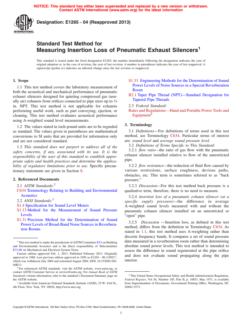
7.2.1 The test apparatus shall consist of a system similar to
compressed air or other gases to be exhausted rapidly. For
that shown in Fig. 1. The critical elements are the compressor-
example, in an automatic pneumatic press, compressed air
tank capacity, size of supply pipes and method of assembly,
must be exhausted rapidly to avoid a premature second cycle.
lengths of certain pipe sections, and design of devices in the air
For this reason, flow ratio is reported in addition to acoustical
stream (that is, valves, regulators, flow meters, temperature,
performance.
and pressure sensors).
7.2.1.1 Reservoir Capacity—The minimum air reservoir
6. Assumptions
size is determined by the maximum unrestricted pipe diameter
planned for the test. Use a reservoir whose size is adequate to
6.1 Studies have shown that the sound level (in decibels)
permit obtaining three contiguous 1 s average sound levels
produced by quieted pneumatic exhausts generally is linear
within 2 dB of each other (see 9.3.3.2).
with supply pressure for the range of pressures covered in this
test method. It is assumed that the air supply pressures called
NOTE 2—Based on experience, the minimum storage tank capacity for
3 3
for in this test method include those typical of most applica- testing ⁄8 in. NPT devices is approximately 2.8 ft (0.08 m ). The
minimum air reservoir size should be increased proportionally for larger
tions. Sound levels may be extrapolated for silencers operating
test specimens.
atpressuresslightlybeyondthetestrange.Alinearrelationship
7.2.1.2 If a dedicated compressor and air reservoir are
can be assumed between discrete test supply pressures.
located near the test site and the piping meets the
6.2 Generally, the sound power produced by pneumatic
exhausts is dominant in the frequency range from 500 to
10 000 Hz. This frequency range allows testing in a relatively
The Magnehelic gage, available from F.W. Dwyer Co., P. O. Box 3029, 1123
small reveberation room.ANSI Standard S 1.33 (AppendixA),
Mearns Rd., Ivyland, PA 18974, or equivalent, has been found satisfactory for this
provides guidelines for the design of an appropriate test room. measurement.
E1265 − 04 (2013)
FIG. 1 Apparatus for Pneumatic Exhaust Silencers
specifications, the separate air reservoir of 7.2.1.1 may be
eliminated. Once the required supply pressure has been
reached, the compressor motor must be shut down to ensure
that the compressor does not restrict as the air pressure is
released for the test.
7.2.1.3 Water Trap—The system shall be equipped with a
water trap (preferably at the tank outlet) to collect condensed
water and provide a means for draining moisture from the
system.
7.2.1.4 Supply Pipes—All pipes in the system shall be
Schedule 40 cast iron, steel, copper, or poly(vinyl chloride)
(PCV). The final downstream segment of pipe shall be a
minimum of 1 m-long steel or cast iron, appropriately sized for
the pneumatic exhaust silencer under test.
NOTE 3—Steel or cast iron is necessary to reduce transmission of sound
through the pipe wall into the reverberation room.
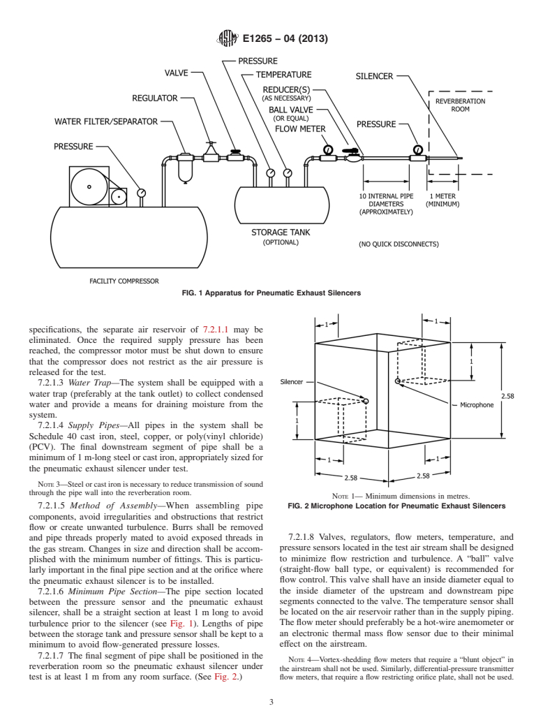
NOTE 1— Minimum dimensions in metres.
7.2.1.5 Method of Assembly—When assembling pipe FIG. 2 Microphone Location for Pneumatic Exhaust Silencers
components, avoid irregularities and obstructions that restrict
flow or create unwanted turbulence. Burrs shall be removed
7.2.1.8 Valves, regulators, flow meters, temperature, and
and pipe threads properly mated to avoid exposed threads in
pressure sensors located in the test air stream shall be designed
the gas stream. Changes in size and direction shall be accom-
to minimize flow restriction and turbulence. A “ball” valve
plished with the minimum number of fittings. This is particu-
(straight-flow ball type, or equivalent) is recommended for
larly important in the final pipe section and at the orifice where
flow control. This valve shall have an inside diameter equal to
the pneumatic exhaust silencer is to be installed.
the inside diameter of the upstream and downstream pipe
7.2.1.6 Minimum Pipe Section—The pipe section located
segments connected to the valve. The temperature sensor shall
between the pressure sensor and the pneumatic exhaust
be located on the air reservoir rather than in the supply piping.
silencer, shall be a straight section at least 1 m long to avoid
The flow meter should preferably be a hot-wire anemometer or
turbulence prior to the silencer (see Fig. 1). Lengths of pipe
an electronic thermal mass flow sensor due to their minimal
between the storage tank and pressure sensor shall be kept to a
effect on the airstream.
minimum to avoid flow-generated pressure losses.
7.2.1.7 The final segment of pipe shall be positioned in the
NOTE 4—Vortex-shedding flow meters that require a “blunt object” in
reverberation room so the pneumatic exhaust silencer under
the airstream shall not be used. Similarly, differential-pressure transmitter
test is at least 1 m from any room surface. (See Fig. 2.) flow meters, that require a flow restricting orifice plate, shall not be used.
E1265 − 04 (2013)
It may be possible to use a differential-pressure transmitter flow meter in
such as those maintained by the National Institute of Standards
conjunction with a venturi, flow nozzle, or pitot tube to minimize flow
and Technology (NIST).
restriction.
9.1.2.2 Prior to each test session, calibrate the flow mea-
7.2.1.9 Precision Regulator, shall be provided prior to the
surement equipment.
air reservoir specified in 7.2.1.1. This regulator shall not allow
9.1.2.3 Establish accuracy and linearity of the flow mea-
pressure in the air reservoir to vary more than 2 % regardless
surement system by determining flow of the unrestricted pipe
of supply pressure variation.
with known conditions. Volume of the storage tank must be
7.2.1.10 “In-line” silencers (for treatment of sound within
determined as well as pressure and temperature of the com-
the airstream) are not recommended. These silencers may
pressed air. Measure flow over some specific brief period of
create undesirable flow restriction or turbulence. Sound propa-
time and determine the subsequent pressure and temperature.
g
...
Questions, Comments and Discussion
Ask us and Technical Secretary will try to provide an answer. You can facilitate discussion about the standard in here.