


ASTM C841-03(2018)
(Specification)Standard Specification for Installation of Interior Lathing and Furring
Standard Specification for Installation of Interior Lathing and Furring
ABSTRACT
This specification covers the minimum requirements for, and the methods of application of, interior lathing and furring to receive gypsum plaster applied. Other materials are not prohibited from being used provided that their physical characteristics and durability under conditions of usage are at least equal in performance to those described. All materials shall be kept dry, preferably by being stored inside. Where necessary to be stored outside, materials shall be stacked off the ground, supported on a level platform, and protected from the weather and surface contamination. Materials shall be neatly stacked flat with care taken to avoid damage to edges, ends, or surfaces. The materials to be used are the following: tie wire and hanger wire, gypsum lath, expanded metal lath, welded wire lath, woven wire lath, nails, screws, staples, paper, and accessories such as control joints, cornerite, channels, rod and flat hangers, clips, and striplath. In general, during installation, the following shall be required: application of gypsum lath to supports, application of gypsum lath to wood supports, application of gypsum lath to metal supports, studless solid partitions (gypsum lath and plaster), application of metal plaster bases to framing members, studless solid partitions (metal lath and plaster), suspended and furred ceilings (metal lath and gypsum lath construction), main runners, cross furring, and metal furring for walls.
SCOPE
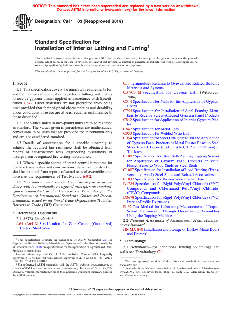
1.1 This specification covers the minimum requirements for, and the methods of application of, interior lathing and furring to receive gypsum plaster applied in accordance with Specification C842. Other materials are not prohibited from being used provided that their physical characteristics and durability under conditions of usage are at least equal in performance to those described.
1.2 The values stated in inch-pound units are to be regarded as standard. The values given in parentheses are mathematical conversions to SI units that are provided for information only and are not considered standard.
1.3 Details of construction for a specific assembly to achieve the required fire resistance shall be obtained from reports of fire-resistance tests, engineering evaluations, or listings from recognized fire testing laboratories.
1.4 Where a specific degree of sound control is required for plastered assemblies and constructions, details of construction shall be obtained from reports of sound tests of assemblies that have met the requirements of Test Method E492.
1.5 This international standard was developed in accordance with internationally recognized principles on standardization established in the Decision on Principles for the Development of International Standards, Guides and Recommendations issued by the World Trade Organization Technical Barriers to Trade (TBT) Committee.
General Information
Buy Standard
Standards Content (Sample)
NOTICE: This standard has either been superseded and replaced by a new version or withdrawn.
Contact ASTM International (www.astm.org) for the latest information
Designation: C841 − 03 (Reapproved 2018)
Standard Specification for
Installation of Interior Lathing and Furring
This standard is issued under the fixed designation C841; the number immediately following the designation indicates the year of
original adoption or, in the case of revision, the year of last revision. A number in parentheses indicates the year of last reapproval. A
superscript epsilon (´) indicates an editorial change since the last revision or reapproval.
This standard has been approved for use by agencies of the U.S. Department of Defense.
1. Scope C11 Terminology Relating to Gypsum and Related Building
Materials and Systems
1.1 This specification covers the minimum requirements for,
C37/C37M Specification for Gypsum Lath (Withdrawn
and the methods of application of, interior lathing and furring
2004)
to receive gypsum plaster applied in accordance with Specifi-
C514 Specification for Nails for the Application of Gypsum
cation C842. Other materials are not prohibited from being
Board
used provided that their physical characteristics and durability
C754 Specification for Installation of Steel Framing Mem-
under conditions of usage are at least equal in performance to
bers to Receive Screw-Attached Gypsum Panel Products
those described.
C842 Specification for Application of Interior Gypsum Plas-
1.2 The values stated in inch-pound units are to be regarded
ter
as standard. The values given in parentheses are mathematical
C847 Specification for Metal Lath
conversions to SI units that are provided for information only
C933 Specification for Welded Wire Lath
and are not considered standard.
C954 Specification for Steel Drill Screws for the Application
1.3 Details of construction for a specific assembly to of Gypsum Panel Products or Metal Plaster Bases to Steel
Studs from 0.033 in. (0.84 mm) to 0.112 in. (2.84 mm) in
achieve the required fire resistance shall be obtained from
reports of fire-resistance tests, engineering evaluations, or Thickness
C1002 Specification for Steel Self-Piercing Tapping Screws
listings from recognized fire testing laboratories.
for Application of Gypsum Panel Products or Metal
1.4 Where a specific degree of sound control is required for
Plaster Bases to Wood Studs or Steel Studs
plastered assemblies and constructions, details of construction
C1007 Specification for Installation of Load Bearing (Trans-
shall be obtained from reports of sound tests of assemblies that
verse and Axial) Steel Studs and Related Accessories
have met the requirements of Test Method E492.
C1032 Specification for Woven Wire Plaster Base
1.5 This international standard was developed in accor-
D1784 Specification for Rigid Poly(Vinyl Chloride) (PVC)
dance with internationally recognized principles on standard-
Compounds and Chlorinated Poly(Vinyl Chloride)
ization established in the Decision on Principles for the
(CPVC) Compounds
Development of International Standards, Guides and Recom-
D3678 Specification for Rigid Poly(Vinyl Chloride) (PVC)
mendations issued by the World Trade Organization Technical
Interior-Profile Extrusions
Barriers to Trade (TBT) Committee.
E492 Test Method for Laboratory Measurement of Impact
Sound Transmission Through Floor-Ceiling Assemblies
2. Referenced Documents
Using the Tapping Machine
2.1 ASTM Standards:
2.2 National Association of Architectural Metal Manufac-
A641/A641M Specification for Zinc–Coated (Galvanized)
turers Standard
Carbon Steel Wire
HMMA 840 Installation and Storage of Hollow Metal Doors
and Frames
This specification is under the jurisdiction of ASTM Committee C11 on
3. Terminology
Gypsum and Related Building Materials and Systems and is the direct responsibility
of Subcommittee C11.03 on Specifications for the Application of Gypsum and Other
3.1 Definitions—For definitions relating to ceilings and
Products in Assemblies.
walls see Terminology C11.
Current edition approved Oct. 1, 2018. Published October 2018. Originally
approved in 1976. Last previous edition approved in 2013 as C841 – 03 (2013).
DOI: 10.1520/C0841-03R18. The last approved version of this historical standard is referenced on
For referenced ASTM standards, visit the ASTM website, www.astm.org, or www.astm.org.
contact ASTM Customer Service at service@astm.org. For Annual Book of ASTM Available from National Association of Architectural Metal Manufacturers
Standards volume information, refer to the standard’s Document Summary page on (NAAMM), 800 Roosevelt Road, Bldg. C, Suite 312, Glen Ellyn, IL 60137,
the ASTM website. http://www.naamm.org.
*A Summary of Changes section appears at the end of this standard
Copyright © ASTM International, 100 Barr Harbor Drive, PO Box C700, West Conshohocken, PA 19428-2959. United States
C841 − 03 (2018)
3.2 Definitions of Terms Specific to This Standard:
Wire Gauge (U.S. Steel
A
Diameter, in. (Diameter, mm)
Wire Gauge)
3.2.1 base coat, n—the sum of the scratch and brown coats
0.0348 (0.88) No. 20
or the total coats in place prior to application of finish coats.
0.0410 (1.04) No. 19
0.0475 (1.21) No. 18
3.2.2 contact ceiling, n—a ceiling in which the lath is
0.0540 (1.37) No. 17
attached in direct contact with the construction above, without
0.0625 (1.59) No. 16
the use of main runners or cross furring.
0.0800 (2.03) No. 14
0.0915 (2.32) No. 13
3.2.3 furred ceiling, n—a ceiling in which the furring used
0.1055 (2.68) No. 12
for the support of the lath is attached directly to the structural
0.1205 (3.06) No. 11
0.1350 (3.43) No. 10
members of the building.
0.1483 (3.77) No. 9
3.2.4 suspended ceiling, n—a ceiling in which the main
0.1620 (4.11) No. 8
A
runners and cross furring are suspended below the structural
Allowable variations in diameter shall be in accordance with tolerances as
established in A641/A641M.
members of the building.
3.2.5 main runners, n—the members that are attached to or 6.2 Gypsum Lath—Specification C37/C37M.
suspended from the construction above for the support of cross
6.3 Expanded Metal Lath—Specification C847.
furring.
6.4 Wire Lath:
3.2.6 cross furring, n—furring members that are attached at
6.4.1 Welded Wire Lath, Specification C933.
right angles to the underside of the main runners or construc-
6.4.2 Woven Wire Lath, Specification C1032.
tion above for support of the lath.
6.5 Fasteners:
3.2.7 furring, n—spacer strips fastened to a wall, ceiling, or
6.5.1 Nails for Attaching Gypsum Lath—Specification
planar element that create an even surface for the application of
metal plaster bases or gypsum lath. C514. Nail size shall be in accordance with Table 1.
6.5.2 Nails for Attaching Metal Plaster Base—Galvanized
3.2.8 primary members, n—the members (main runners or
roofing nails or common nails. length shall be as specified in
structural supports) to which the cross furring is attached.
Section 7.
3.2.9 metal plaster bases, n—expanded metal lath, sheet
6.5.3 Screws—Specifications C954 or C1002.
metal lath, welded or woven wire lath.
6.5.3.1 Screws for attaching gypsum lath shall be sized in
3.2.10 face side (gypsum lath), n—the side opposite the
accordance with Table 1.
paper cover seam laps.
6.5.3.2 Screws for attaching metal plaster base shall have a
3.2.11 surface transition, n—the change in width of a 7
⁄16 in. (11.1 mm) diameter pan washer head and a 0.120 in.
surface, usually as a result of penetrations (doors, windows) or
(3.0 mm) diameter shank. The length shall be sufficient enough
architectural demands.
to allow for the threaded portion of the screw to project not less
than ⁄8 in. (9.5 mm) through steel framing when the lath is
4. Delivery of Materials
installed.
4.1 All materials shall be delivered in the original packages,
6.5.4 Staples—Staples for attaching gypsum lath shall con-
containers, or bundles bearing the brand name and manufac-
form to the requirements of Table 1.
turer’s (or supplier’s) identification.
6.5.4.1 Staples for attaching metal plaster base shall be
0.062 in. (1.6 mm) diameter, round or flattened steel wire with
5. Storage of Materials
⁄4 in. (19.0 mm) crown. Lengths shall be as specified for
5.1 All materials shall be kept dry, preferably by being
individual systems.
stored inside. Where necessary to be stored outside, materials
6.6 Paper or Other Backing—When used on metal plaster
shall be stacked off the ground, supported on a level platform,
bases, over solid backing, backing shall be securely held in
and protected from the weather and surface contamination.
place by, or attached to the metal plaster base. Metal plaster
5.2 Materials shall be neatly stacked flat with care taken to
base shall allow for ⁄4 in. (6.4 mm) self furring. The backing
avoid damage to edges, ends, or surfaces.
shall permit embedment of plaster.
6. Materials
6.7 Accessories—Shall be steel, coated, with a protective
rust inhibitive coating after fabrication, or fabricated from
6.1 Wire Specification A641/A641M, Class 1 coating (gal-
zinc-coated (galvanized) steel, aluminum, zinc alloy, or high
vanized) soft temper.
impact plastic. Plastic accessories shall be manufactured in
6.1.1 Tie Wire and Hanger Wire—Zinc-coated (galvanized)
accordance with Specification D1784 or D3678. Aluminum
soft-annealed steel, or a material having equivalent size,
accessories shall be clear plastic coated. All accessories shall
corrosion resistance and strength. Wire diameters (uncoated)
have perforated or expanded flanges or clips shaped so as to
specified herein correspond with United States steel wire gauge
permit complete imbedment in the plaster, to provide means for
numbers as follows:
secure alignment, and to secure attachment of the accessory to
the underlying surface. Accessories shall be designed for the
intended use and to receive or to permit application of the
specified plaster thickness.
C841 − 03 (2018)
A,B
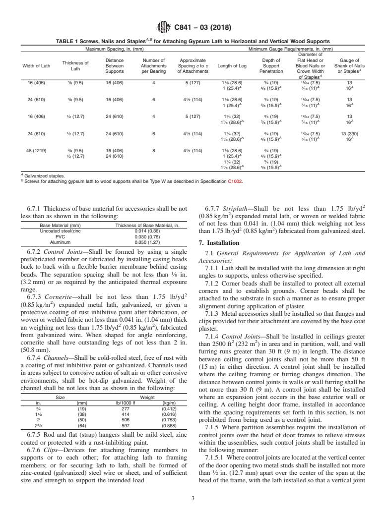
TABLE 1 Screws, Nails and Staples for Attaching Gypsum Lath to Horizontal and Vertical Wood Supports
Maximum Spacing, in. (mm) Minimum Gauge Requirements, in. (mm)
Diameter of
Distance Number of Approximate Depth of Flat Head or Gauge of
Thickness of
Width of Lath Between Attachments Spacing c to c Length of Leg Support Blued Nails or Shank of Nails
Lath
A
Supports per Bearing of Attachments Penetration Crown Width or Staples
A
of Staples
3 1 3 19
16 (406) ⁄8 (9.5) 16 (406) 4 5 (127) 1 ⁄8 (28.6) ⁄4 (19) ⁄64 (7.5) 13
A A A A
5 7
1 (25.4) ⁄8 (15.9) ⁄16 (11) 16
3 1 1 3 19
24 (610) ⁄8 (9.5) 16 (406) 6 4 ⁄2 (114) 1 ⁄8 (28.6) ⁄4 (19) ⁄64 (7.5) 13
A A A A
5 7
1 (25.4) ⁄8 (15.9) ⁄16 (11) 16
1 1 3 19
16 (406) ⁄2 (12.7) 24 (610) 4 5 (127) 1 ⁄4 (32) ⁄4 (19) ⁄64 (7.5) 13
A A A A
1 5 7
1 ⁄8 (28.6) ⁄8 (15.9) ⁄16 (11) 16
1 1 1 3 19
24 (610) ⁄2 (12.7) 24 (610) 6 4 ⁄2 (114) 1 ⁄4 (32) ⁄4 (19) ⁄64 (7.5) 13 (330)
A A A A
1 5 7
1 ⁄8 (28.6) ⁄8 (15.9) ⁄16 (11) 16
3 1 1 3
48 (1219) ⁄8 (9.5) 16 (406) 8 4 ⁄2 (114) 1 ⁄8 (28.6) ⁄4 (19)
A A
1 5
⁄2 (12.7) 24 (610) 1 (25.4) ⁄8 (15.9)
1 3
1 ⁄4 (32) ⁄4 (19)
1 A 5 A
1 ⁄8 (28.6) ⁄8 (15.9)
A
Galvanized staples.
B
Screws for attaching gypsum lath to wood supports shall be Type W as described in Specification C1002.
6.7.1 Thickness of base material for accessories shall be not 6.7.7 Striplath—Shall be not less than 1.75 lb/yd
less than as shown in the following: (0.85 kg ⁄m ) expanded metal lath, or woven or welded fabric
of not less than 0.041 in. (1.04 mm) thick weighing not less
Base Material (mm) Thickness of Base Material, in.
2 2
Uncoated steel/zinc 0.014 (0.36)
than 1.75 lb ⁄yd (0.85 kg/m ) fabricated from galvanized steel.
PVC 0.030 (0.76)
Aluminum 0.050 (1.27)
7. Installation
6.7.2 Control Joints—Shall be formed by using a single
7.1 General Requirements for Application of Lath and
prefabricated member or fabricated by installing casing beads
Accessories:
back to back with a flexible barrier membrane behind casing
7.1.1 Lath shall be installed with the long dimension at right
beads. The separation spacing shall be not less than ⁄8 in.
angles to supports, unless otherwise specified.
(3.2 mm) or as required by the anticipated thermal exposure
7.1.2 Corner beads shall be installed to protect all external
range.
corners and to establish grounds. Corner beads shall be
6.7.3 Cornerite—shall be not less than 1.75 lb/yd
attached to the substrate in such a manner as to ensure proper
(0.85 kg ⁄m ) expanded metal lath, galvanized, or given a
alignment during application of plaster.
protective coating of rust inhibitive paint after fabrication, or
7.1.3 Metal accessories shall be installed so that flanges and
woven or welded fabric not less than 0.041 in. (1.04 mm) thick
clips provided for their attachment are covered by the base coat
2 2
an weighing not less than 1.75 lb/yd (0.85 kg/m ), fabricated
plaster.
from galvanized wire. When shaped for angle reinforcing,
7.1.4 Control Joints—Shall be installed in ceilings greater
2 2
cornerite shall have outstanding legs of not less than 2 in.
than 2500 ft (232 m ) in area and in partition, wall, and wall
(50.8 mm).
furring runs greater than 30 ft (9 m) in length. The distance
6.7.4 Channels—Shall be cold-rolled steel, free of rust with
between ceiling control joints shall not be more than 50 ft
a coating of rust inhibitive paint or galvanized. Channels used
(15 m) in either direction. A control joint shall be installed
in areas subject to corrosive action of salt air or other corrosive
where the ceiling framing or furring changes direction. The
environments, shall be hot-dip galvanized. Weight of the
distance between control joints in walls or wall furring shall be
channel shall be not less than as shown in the following:
not more than 30 ft (9 m). A control joint shall be installed
Size Weight where an expansion joint occurs in the base exterior wall or
in. (mm) lb/1000 lf (kg/m)
ceiling. A ceiling height door frame, installed in accordance
⁄4 (19) 277 (0.412)
with the spacing requirements set forth in this section, is not
1 ⁄2 (38) 414 (0.616)
2 (50) 506 (0.753)
prohibited from being used as a control joint.
2 ⁄2 (64) 597 (0.888)
7.1.5 Where partition assemblies require the installation of
6.7.5 Rod and flat (strap) hangers shall be mild steel, zinc control joints over the head of door frames to relieve stresses
coated or protected with a rust-inhibiting paint. within the assemblies, such control joints shall be installed in
6.7.6 Clips—Devices for attaching framing members to the following manner:
supports or to each other; for attaching lath to framing 7.1.5.1 Where control joints are located at the vertical center
members; or for securing lath to lath, shall be formed of of the door opening two metal studs shall be installed not more
zinc-coated (galvanized) steel wire or sheet, and of sufficient than ⁄2 in. (12.7 mm) apart over the center of the span at t
...
This document is not an ASTM standard and is intended only to provide the user of an ASTM standard an indication of what changes have been made to the previous version. Because
it may not be technically possible to adequately depict all changes accurately, ASTM recommends that users consult prior editions as appropriate. In all cases only the current version
of the standard as published by ASTM is to be considered the official document.
Designation: C841 − 03 (Reapproved 2013) C841 − 03 (Reapproved 2018)
Standard Specification for
Installation of Interior Lathing and Furring
This standard is issued under the fixed designation C841; the number immediately following the designation indicates the year of
original adoption or, in the case of revision, the year of last revision. A number in parentheses indicates the year of last reapproval. A
superscript epsilon (´) indicates an editorial change since the last revision or reapproval.
This standard has been approved for use by agencies of the U.S. Department of Defense.
1. Scope
1.1 This specification covers the minimum requirements for, and the methods of application of, interior lathing and furring to
receive gypsum plaster applied in accordance with Specification C842. Other materials are not prohibited from being used provided
that their physical characteristics and durability under conditions of usage are at least equal in performance to those described.
1.2 The values stated in inch-pound units are to be regarded as standard. The values given in parentheses are mathematical
conversions to SI units that are provided for information only and are not considered standard.
1.3 Details of construction for a specific assembly to achieve the required fire resistance shall be obtained from reports of
fire-resistance tests, engineering evaluations, or listings from recognized fire testing laboratories.
1.4 Where a specific degree of sound control is required for plastered assemblies and constructions, details of construction shall
be obtained from reports of sound tests of assemblies that have met the requirements of Test Method E492.
1.5 This international standard was developed in accordance with internationally recognized principles on standardization
established in the Decision on Principles for the Development of International Standards, Guides and Recommendations issued
by the World Trade Organization Technical Barriers to Trade (TBT) Committee.
2. Referenced Documents
2.1 ASTM Standards:
A641/A641M Specification for Zinc–Coated (Galvanized) Carbon Steel Wire
C11 Terminology Relating to Gypsum and Related Building Materials and Systems
C37/C37M Specification for Gypsum Lath (Withdrawn 2004)
C514 Specification for Nails for the Application of Gypsum Board
C754 Specification for Installation of Steel Framing Members to Receive Screw-Attached Gypsum Panel Products
C842 Specification for Application of Interior Gypsum Plaster
C847 Specification for Metal Lath
C933 Specification for Welded Wire Lath
C954 Specification for Steel Drill Screws for the Application of Gypsum Panel Products or Metal Plaster Bases to Steel Studs
from 0.033 in. (0.84 mm) to 0.112 in. (2.84 mm) in Thickness
C1002 Specification for Steel Self-Piercing Tapping Screws for Application of Gypsum Panel Products or Metal Plaster Bases
to Wood Studs or Steel Studs
C1007 Specification for Installation of Load Bearing (Transverse and Axial) Steel Studs and Related Accessories
C1032 Specification for Woven Wire Plaster Base
D1784 Specification for Rigid Poly(Vinyl Chloride) (PVC) Compounds and Chlorinated Poly(Vinyl Chloride) (CPVC)
Compounds
D3678 Specification for Rigid Poly(Vinyl Chloride) (PVC) Interior-Profile Extrusions
E492 Test Method for Laboratory Measurement of Impact Sound Transmission Through Floor-Ceiling Assemblies Using the
Tapping Machine
This specification is under the jurisdiction of ASTM Committee C11 on Gypsum and Related Building Materials and Systems and is the direct responsibility of
Subcommittee C11.03 on Specifications for the Application of Gypsum and Other Products in Assemblies.
Current edition approved Oct. 1, 2013Oct. 1, 2018. Published October 2013October 2018. Originally approved in 1976. Last previous edition approved in 20082013 as
C841 – 03 (2008)(2013).ε1. DOI: 10.1520/C0841-03R13.10.1520/C0841-03R18.
For referenced ASTM standards, visit the ASTM website, www.astm.org, or contact ASTM Customer Service at service@astm.org. For Annual Book of ASTM Standards
volume information, refer to the standard’s Document Summary page on the ASTM website.
The last approved version of this historical standard is referenced on www.astm.org.
*A Summary of Changes section appears at the end of this standard
Copyright © ASTM International, 100 Barr Harbor Drive, PO Box C700, West Conshohocken, PA 19428-2959. United States
C841 − 03 (2018)
2.2 National Association of Architectural Metal Manufacturers Standard
HMMA 840 Installation and Storage of Hollow Metal Doors and Frames
3. Terminology
3.1 Definitions—For definitions relating to ceilings and walls see Terminology C11.
3.2 Definitions of Terms Specific to This Standard:
3.2.1 base coat, n—the sum of the scratch and brown coats or the total coats in place prior to application of finish coats.
3.2.2 contact ceiling, n—a ceiling in which the lath is attached in direct contact with the construction above, without the use
of main runners or cross furring.
3.2.3 furred ceiling, n—a ceiling in which the furring used for the support of the lath is attached directly to the structural
members of the building.
3.2.4 suspended ceiling, n—a ceiling in which the main runners and cross furring are suspended below the structural members
of the building.
3.2.5 main runners, n—the members that are attached to or suspended from the construction above for the support of cross
furring.
3.2.6 cross furring, n—furring members that are attached at right angles to the underside of the main runners or construction
above for support of the lath.
3.2.7 furring, n—spacer strips fastened to a wall, ceiling, or planar element that create an even surface for the application of
metal plaster bases or gypsum lath.
3.2.8 primary members, n—the members (main runners or structural supports) to which the cross furring is attached.
3.2.9 metal plaster bases, n—expanded metal lath, sheet metal lath, welded or woven wire lath.
3.2.10 face side (gypsum lath), n—the side opposite the paper cover seam laps.
3.2.11 surface transition, n—the change in width of a surface, usually as a result of penetrations (doors, windows) or
architectural demands.
4. Delivery of Materials
4.1 All materials shall be delivered in the original packages, containers, or bundles bearing the brand name and manufacturer’s
(or supplier’s) identification.
5. Storage of Materials
5.1 All materials shall be kept dry, preferably by being stored inside. Where necessary to be stored outside, materials shall be
stacked off the ground, supported on a level platform, and protected from the weather and surface contamination.
5.2 Materials shall be neatly stacked flat with care taken to avoid damage to edges, ends, or surfaces.
6. Materials
6.1 Wire Specification A641/A641M, Class 1 coating (galvanized) soft temper.
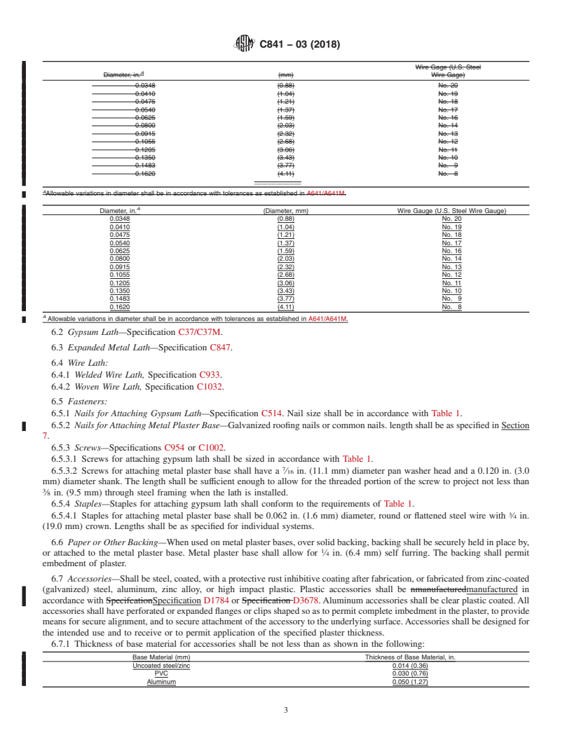
6.1.1 Tie Wire and Hanger Wire—Zinc-coated (galvanized) soft-annealed steel, or a material having equivalent size, corrosion
resistance and strength. Wire diameters (uncoated) specified herein correspond with United States steel wire gagegauge numbers
as follows:
Available from National Association of Architectural Metal Manufacturers (NAAMM), 800 Roosevelt Road, Bldg. C, Suite 312, Glen Ellyn, IL 60137,
http://www.naamm.org.
C841 − 03 (2018)
Wire Gage (U.S. Steel
A
Diameter, in. (mm) Wire Gage)
0.0348 (0.88) No. 20
0.0410 (1.04) No. 19
0.0475 (1.21) No. 18
0.0540 (1.37) No. 17
0.0625 (1.59) No. 16
0.0800 (2.03) No. 14
0.0915 (2.32) No. 13
0.1055 (2.68) No. 12
0.1205 (3.06) No. 11
0.1350 (3.43) No. 10
0.1483 (3.77) No. 9
0.1620 (4.11) No. 8
_____________
A
Allowable variations in diameter shall be in accordance with tolerances as established in A641/A641M.
A
Diameter, in. (Diameter, mm) Wire Gauge (U.S. Steel Wire Gauge)
0.0348 (0.88) No. 20
0.0410 (1.04) No. 19
0.0475 (1.21) No. 18
0.0540 (1.37) No. 17
0.0625 (1.59) No. 16
0.0800 (2.03) No. 14
0.0915 (2.32) No. 13
0.1055 (2.68) No. 12
0.1205 (3.06) No. 11
0.1350 (3.43) No. 10
0.1483 (3.77) No. 9
0.1620 (4.11) No. 8
A
Allowable variations in diameter shall be in accordance with tolerances as established in A641/A641M.
6.2 Gypsum Lath—Specification C37/C37M.
6.3 Expanded Metal Lath—Specification C847.
6.4 Wire Lath:
6.4.1 Welded Wire Lath, Specification C933.
6.4.2 Woven Wire Lath, Specification C1032.
6.5 Fasteners:
6.5.1 Nails for Attaching Gypsum Lath—Specification C514. Nail size shall be in accordance with Table 1.
6.5.2 Nails for Attaching Metal Plaster Base—Galvanized roofing nails or common nails. length shall be as specified in Section
7.
6.5.3 Screws—Specifications C954 or C1002.
6.5.3.1 Screws for attaching gypsum lath shall be sized in accordance with Table 1.
6.5.3.2 Screws for attaching metal plaster base shall have a ⁄16 in. (11.1 mm) diameter pan washer head and a 0.120 in. (3.0
mm) diameter shank. The length shall be sufficient enough to allow for the threaded portion of the screw to project not less than
⁄8 in. (9.5 mm) through steel framing when the lath is installed.
6.5.4 Staples—Staples for attaching gypsum lath shall conform to the requirements of Table 1.
6.5.4.1 Staples for attaching metal plaster base shall be 0.062 in. (1.6 mm) diameter, round or flattened steel wire with ⁄4 in.
(19.0 mm) crown. Lengths shall be as specified for individual systems.
6.6 Paper or Other Backing—When used on metal plaster bases, over solid backing, backing shall be securely held in place by,
or attached to the metal plaster base. Metal plaster base shall allow for ⁄4 in. (6.4 mm) self furring. The backing shall permit
embedment of plaster.
6.7 Accessories—Shall be steel, coated, with a protective rust inhibitive coating after fabrication, or fabricated from zinc-coated
(galvanized) steel, aluminum, zinc alloy, or high impact plastic. Plastic accessories shall be nmanufacturedmanufactured in
accordance with SpecifcationSpecification D1784 or Specification D3678. Aluminum accessories shall be clear plastic coated. All
accessories shall have perforated or expanded flanges or clips shaped so as to permit complete imbedment in the plaster, to provide
means for secure alignment, and to secure attachment of the accessory to the underlying surface. Accessories shall be designed for
the intended use and to receive or to permit application of the specified plaster thickness.
6.7.1 Thickness of base material for accessories shall be not less than as shown in the following:
Base Material (mm) Thickness of Base Material, in.
Uncoated steel/zinc 0.014 (0.36)
PVC 0.030 (0.76)
Aluminum 0.050 (1.27)
C841 − 03 (2018)
A,B
TABLE 1 Screws, Nails and Staples for Attaching Gypsum Lath to Horizontal and Vertical Wood Supports
Maximum Spacing, in. (mm) Minimum Gage Requirements, in. (mm)
Diameter of
Approximate Flat Head or Gage of
Distance Number of Depth of
Width of Thickness Spacing c to c Length of Blued Nails Shank of
Between Attachments Support
Lath of Lath of Leg or Crown Nails or
Supports per Bearing Penetration
A
Attachments Width of Staples
A
Staples
Maximum Spacing, in. (mm) Minimum Gauge Requirements, in. (mm)
Diameter of
Distance Number of Approximate Depth of Flat Head or Gauge of
Thickness of
Width of Lath Between Attachments Spacing c to c Length of Leg Support Blued Nails or Shank of Nails
Lath
A
Supports per Bearing of Attachments Penetration Crown Width or Staples
A
of Staples
3 1 3 19
16 (406) ⁄8 (9.5) 16 (406) 4 5 (127) 1 ⁄8 (28.6) ⁄4 (19) ⁄64 (7.5) 13
A A A A
5 7
1 (25.4) ⁄8 (15.9) ⁄16 (11) 16
3 1 1 3 19
24 (610) ⁄8 (9.5) 16 (406) 6 4 ⁄2 (114) 1 ⁄8 (28.6) ⁄4 (19) ⁄64 (7.5) 13
A 5 A 7 A A
1 (25.4) ⁄8 (15.9) ⁄16 (11) 16
1 1 3 19
16 (406) ⁄2 (12.7) 24 (610) 4 5 (127) 1 ⁄4 (32) ⁄4 (19) ⁄64 (7.5) 13
A A A A
1 5 7
1 ⁄8 (28.6) ⁄8 (15.9) ⁄16 (11) 16
1 1 1 3 19
24 (610) ⁄2 (12.7) 24 (610) 6 4 ⁄2 (114) 1 ⁄4 (32) ⁄4 (19) ⁄64 (7.5) 13 (330)
A A A A
1 5 7
1 ⁄8 (28.6) ⁄8 (15.9) ⁄16 (11) 16
3 1 1 3
48 (1219) ⁄8 (9.5) 16 (406) 8 4 ⁄2 (114) 1 ⁄8 (28.6) ⁄4 (19)
1 A 5 A
⁄2 (12.7) 24 (610) 1 (25.4) ⁄8 (15.9)
1 3
1 ⁄4 (32) ⁄4 (19)
A A
1 5
1 ⁄8 (28.6) ⁄8 (15.9)
A
Galvanized staples.
B
Screws for attaching gypsum lath to wood supports shall be Type W as described in Specification C1002.
Base Material (mm) Thickness of
Base Material, in.
Uncoated steel/zinc 0.014 (0.36)
PVC 0.030 (0.76)
Aluminum 0.050 (1.27)
6.7.2 Control Joints—Shall be formed by using a single prefabricated member or fabricated by installing casing beads back to
back with a flexible barrier membrane behind casing beads. The separation spacing shall be not less than ⁄8 in. (3.2 mm) (3.2 mm)
or as required by the anticipated thermal exposure range.
2 2
6.7.3 Cornerite—shall be not less than 1.75 lb/yd (0.85 (0.85 kg kg/m⁄m ) expanded metal lath, galvanized, or given a
protective coating of rust inhibitive paint after fabrication, or woven or welded fabric not less than 0.041 in. (1.04 mm) thick an
2 2
weighing not less than 1.75 lb/yd (0.85 kg/m ), fabricated from galvanized wire. When shaped for angle reinforcing, cornerite
shall have outstanding legs of not less than 2 in. (50.8 mm).(50.8 mm).
6.7.4 Channels—Shall be cold-rolled steel, free of rust with a coating of rust inhibitive paint or galvanized. Channels used in
areas subject to corrosive action of salt air or other corrosive environments, shall be hot-dip galvanized. Weight of the channel shall
be not less than as shown in the following:
Size Weight
in. (mm) lb/1000 lf (kg/m)
⁄4 (19) 277 (0.412)
1 ⁄2 (38) 414 (0.616)
2 (50) 506 (0.753)
2 ⁄2 (64) 597 (0.888)
Size Weight
in. (mm) lb/1000 lf (kg/m)
⁄4 (19) 277 (0.412)
1 ⁄2 (38) 414 (0.616)
2 (50) 506 (0.753)
2 ⁄2 (64) 597 (0.888)
6.7.5 Rod and flat (strap) hangers shall be mild steel, zinc coated or protected with a rust-inhibiting paint.
6.7.6 Clips—Devices for attaching framing members to supports or to each other; for attaching lath to framing members; or for
securing lath to lath, shall be formed of zinc-coated (galvanized) steel wire or sheet, and of sufficient size and strength to support
the intended load
2 2
6.7.7 Striplath—Shall be not less than 1.75 lb/yd (0.85 (0.85 kg kg/m⁄m ) expanded metal lath, or woven or welded fabric of
2 2
not less than 0.041 in. (1.04 mm) thick weighing not less than 1.75 1.75 lb lb/yd⁄yd (0.85 kg/m ) fabricated from galvanized steel.
C841 − 03 (2018)
7. Installation
7.1 General Requirements for Application of Lath and Accessories:
7.1.1 Lath
...
Questions, Comments and Discussion
Ask us and Technical Secretary will try to provide an answer. You can facilitate discussion about the standard in here.