


ASTM C585-10(2016)
(Practice)Standard Practice for Inner and Outer Diameters of Thermal Insulation for Nominal Sizes of Pipe and Tubing
Standard Practice for Inner and Outer Diameters of Thermal Insulation for Nominal Sizes of Pipe and Tubing
SIGNIFICANCE AND USE
4.1 The purpose of this practice is to ensure satisfactory fit on standard sizes, to accommodate radial expansion of pipes and tubes which are heated after being insulated, and to minimize the number of insulation sizes and thicknesses to be manufactured and stocked.
4.2 While it is possible to manufacturer insulation to these recommended dimensions, exercise care in attempting to nest layers of different materials, or layers supplied by different manufacturers. Individual manufacturing processes will operate at slightly different tolerances. While the product will fit the pipe, it is possible that it will not readily nest as the outer layer between the different materials, or with a different manufacturer, and possibly the same manufacturer. Exercise care to determine these differences before specifying or ordering nesting sizes.
4.3 The wide range of outer diameter dimensional tolerances will prevent many pipe and tube insulations from nesting for staggered joints or double layered applications, or both unless specified when ordered from the manufacturer, distributor, or fabricator.
4.4 Dimensions in accordance with this practice do not necessarily permit application of one thickness of pipe insulation over another (Nesting or Simplified Dimensional System) to obtain total thicknesses greater than those manufactured as single layer, or for multilayer application when desired.
SCOPE
1.1 This practice is intended as a dimensional standard for preformed thermal insulation for pipes and tubing.
1.2 This practice covers insulation supplied in cylindrical sections and lists recommended single layer inner and outer diameters of insulation having nominal wall thicknesses from 1/2 to 5 in. (13 to 127 mm) to fit over standard sizes of pipe and tubing.
1.3 The values stated in inch-pound units are to be regarded as the standard. The values stated in SI units are provided for information only.
1.4 This standard does not purport to address the safety concerns, if any, associated with its use. It is the responsibility of the user of this standard to establish appropriate safety and health practices and determine the applicability of regulatory limitations prior to use.
General Information
Buy Standard
Standards Content (Sample)
NOTICE: This standard has either been superseded and replaced by a new version or withdrawn.
Contact ASTM International (www.astm.org) for the latest information
Designation: C585 − 10 (Reapproved 2016)
Standard Practice for
Inner and Outer Diameters of Thermal Insulation for
Nominal Sizes of Pipe and Tubing
This standard is issued under the fixed designation C585; the number immediately following the designation indicates the year of
original adoption or, in the case of revision, the year of last revision. A number in parentheses indicates the year of last reapproval. A
superscript epsilon (´) indicates an editorial change since the last revision or reapproval.
1. Scope minimize the number of insulation sizes and thicknesses to be
manufactured and stocked.
1.1 This practice is intended as a dimensional standard for
preformed thermal insulation for pipes and tubing.
4.2 While it is possible to manufacturer insulation to these
recommended dimensions, exercise care in attempting to nest
1.2 This practice covers insulation supplied in cylindrical
layers of different materials, or layers supplied by different
sections and lists recommended single layer inner and outer
manufacturers. Individual manufacturing processes will oper-
diameters of insulation having nominal wall thicknesses from
1 ate at slightly different tolerances.While the product will fit the
⁄2 to 5 in. (13 to 127 mm) to fit over standard sizes of pipe and
pipe, it is possible that it will not readily nest as the outer layer
tubing.
between the different materials, or with a different
1.3 The values stated in inch-pound units are to be regarded
manufacturer, and possibly the same manufacturer. Exercise
as the standard. The values stated in SI units are provided for
care to determine these differences before specifying or order-
information only.
ing nesting sizes.
1.4 This standard does not purport to address the safety
4.3 The wide range of outer diameter dimensional toler-
concerns, if any, associated with its use. It is the responsibility
ances will prevent many pipe and tube insulations from nesting
of the user of this standard to establish appropriate safety and
for staggered joints or double layered applications, or both
health practices and determine the applicability of regulatory
unless specified when ordered from the manufacturer,
limitations prior to use.
distributor, or fabricator.
2. Referenced Documents 4.4 Dimensions in accordance with this practice do not
necessarily permit application of one thickness of pipe insula-
2.1 ASTM Standards:
tion over another (Nesting or Simplified Dimensional System)
C168 Terminology Relating to Thermal Insulation
to obtain total thicknesses greater than those manufactured as
C302 Test Method for Density and Dimensions of Pre-
single layer, or for multilayer application when desired.
formed Pipe-Covering-Type Thermal Insulation
5. Summary of Practice
3. Terminology
5.1 This practice provides for each pipe and tubing sizes the
3.1 Definitions—Definitions pertaining to insulation are de-
inner diameters with tolerances for calcium silicate, cellular
fined in Terminology C168.
foam plastics, cellular glass, mineral fiber, and perlite pre-
4. Significance and Use formed pipe and tubing insulation identified by Table 1 and
Table 2.
4.1 The purpose of this practice is to ensure satisfactory fit
on standard sizes, to accommodate radial expansion of pipes
5.2 This practice provides for each pipe and tubing sizes the
and tubes which are heated after being insulated, and to
outer diameters for calcium silicate, cellular foam plastics,
cellular glass, mineral fiber, and perlite preformed pipe and
tubing insulation identified by Table 3, Table 4, Table 5 and
This practice is under the jurisdiction of ASTM Committee C16 on Thermal
Table 6.
InsulationandisthedirectresponsibilityofSubcommitteeC16.20onHomogeneous
Inorganic Thermal Insulations.
5.3 This practice provides for a range of pipe and tubing
Current edition approved May 1, 2016. Published May 2016. Originally
sizes the outer diameter tolerances for calcium silicate and
approvedin1966toreplaceC312andC521.Lastpreviouseditionapprovedin2010
perlitepreformedpipeandtubinginsulationidentifiedbyTable
as C585 – 10. DOI: 10.1520/C0585-10R16.
3a, Table 4a, Table 5a, and Table 6a.
For referenced ASTM standards, visit the ASTM website, www.astm.org, or
contact ASTM Customer Service at service@astm.org. For Annual Book of ASTM
5.4 This practice provides for a range of pipe and tubing
Standards volume information, refer to the standard’s Document Summary page on
the ASTM website. sizes the outer diameters tolerances for cellular foam plastics,
Copyright © ASTM International, 100 Barr Harbor Drive, PO Box C700, West Conshohocken, PA 19428-2959. United States
C585 − 10 (2016)
cellular glass, and mineral fiber, preformed pipe and tubing 6.2.2 Inner diameters and tolerances for nominal sizes of
insulations identified by Table 3b, Table 4b, Table 5b and Table tubing are shown in Table 2, Table 8. Table 8a Table 10 and
6b. Table 10a.
5.5 This practice provides for each pipe and tubing sizes the 6.3 Recommended Outer Diameters:
inner and outer diameters for flexible elastomeric cellular and 6.3.1 Outerdiametersfornominalsizesofpipeareshownin
polyolefin preformed pipe and tubing insulation identified by Table 3 and Table 4, Table 7 and Table 9 and tubing in Table
Table 7, Table 8, Table 9, and Table 10. 5 and Table 6, Table 8, and Table 10. All Tables 3-10 are not
for nesting purposes. When a pipe or tubing insulation product
5.6 This practice provides for a range of pipe and tubing
is to be nested, it shall be so stated on order.
sizes the inner and outer diameter tolerances for flexible
6.3.2 There are no maximum outer diameter tables provided
elastomeric and polyolefin cellular preformed pipe and tubing
for jacketing purposes because of the wide spread variations in
insulation identified by Table 7a, Table 8a, Table 9a, and Table
the outside diameters with their plus or minus tolerances.
10a.
NOTE 1—Previous versions of C585 contained Tables for jacketing
6. Procedure
purposes only.These tables have been removed from this practice with the
inclusion of variable outside diameters caused by the addition of outer
6.1 Measurement:
diameter (OD) tolerances. It is recommended in order to calculate the
6.1.1 Measurement of inner and outer diameters shall be
maximum circumferences for jacketing purposes, determine the pipe or
made to the nearest ⁄32 in. (0.8 mm) using a steel tape or rule.
tube insulation’s maximum outer diameters from the manufacturer. An
6.1.1.1 Uneven Insulation Inner & Outer Circumferential
alternativemeasureforfindingthejacketingstretch-outnumbersistolook
up the outer diameter for the pipe or tubing insulation from the tables; add
Surfaces—Use Test Method C302, Procedure C. This method
the applicable plus (+) outer diameter tolerance and twice the thickness of
must be used, to duplicate fit for application on a pipe and
the jacketing to the insulation outer diameter number; multiply the added
tubing and to determine the final outside diameter when an
total times pī (3.14159) to arrive at the maximum circumference; add the
outer metal jacket system is snugly applied.
necessary longitudinal overlap dimension to the maximum circumference;
6.1.1.2 Half Sections—The diameter reported for each half-
and the calculated answer will be the stretch-out requirement for cutting
the outer jacketing to be applied over / around the pipe or tubing
section shall be the average of six measurements taken at three
insulation’s OD.
locations including two near the ends and one near the center
NOTE 2—NPS (Nominal Pipe Size) is a dimensionless designator that
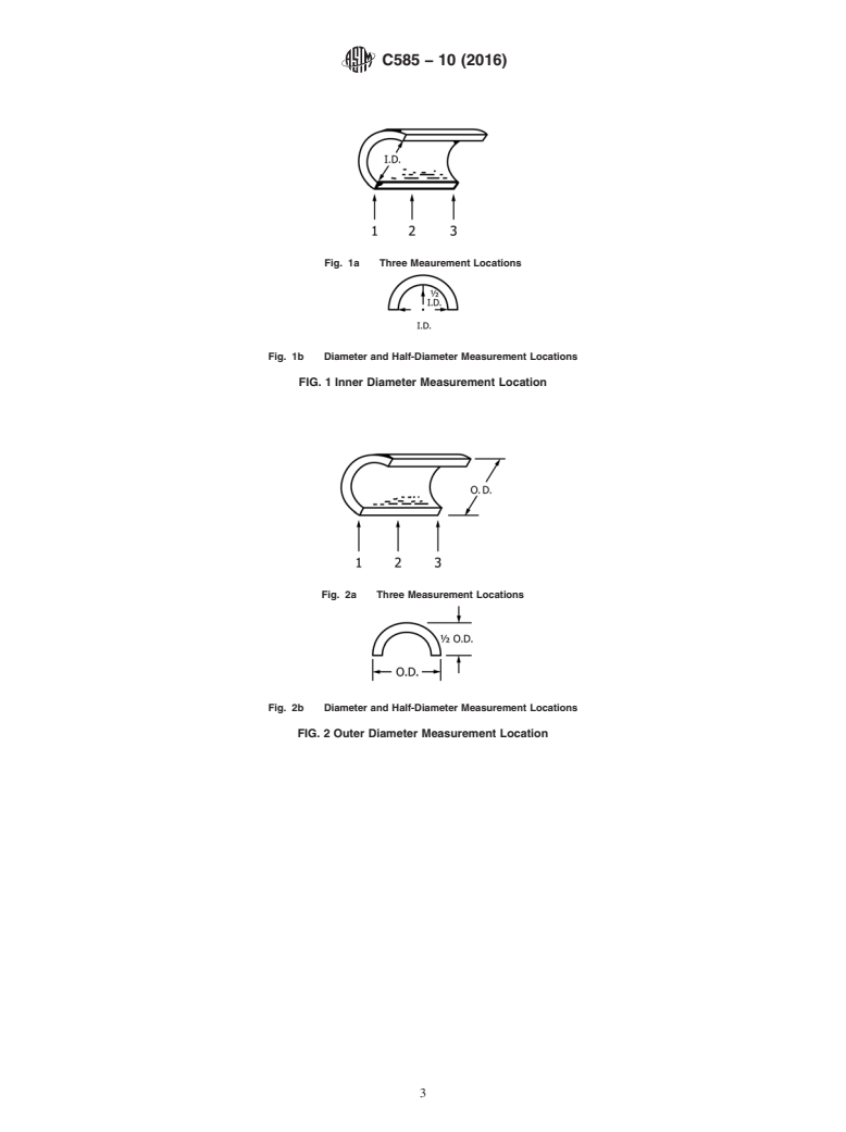
(see Fig. 1a and Fig. 2a). Three of the six readings shall be
has been substituted in the customary units section for the previous term
taken in the longitudinal plane of the flat, cut surface: the other
inch nominal pipe size.
three shall each be twice a half-diameter in the longitudinal
NOTE 3—NTS (Nominal Tube Size) is a dimensionless designator that
has been substituted in the customary units section for the previous term
plane at right angles to that of the first three (see Fig. 1b and
inch nominal tube size.
Fig. 2b).
NOTE 4—DN (Diameter Nominal) is a dimensionless designator that
6.1.1.3 Hinged Sections—The diameter reported for each
has been substituted in the customary units section for the previous term
hinged section shall be the average of four measurements taken
SI (metric) system to describe millimeter nominal pipe or tube size.
at both ends of the section (two per end) (see Fig. 3). The two
measurements at each end shall be at right angles. 7. Keywords
6.2 Recommended Inner Diameters: 7.1 pipe thermal insulation diameter; pipe thermal insula-
6.2.1 Inner diameters and tolerances for nominal sizes of tion dimension; thermal insulating materials-pipe; thermal
insulation for pipe are shown in Table 1, Table 7. Table 7a insulating materials-tubing; thermal insulation; tubing thermal
Table 9 and Table 9a. insulation diameter; tubing thermal insulation dimension
C585 − 10 (2016)
Fig. 1a Three Meaurement Locations
Fig. 1b Diameter and Half-Diameter Measurement Locations
FIG. 1 Inner Diameter Measurement Location
Fig. 2a Three Measurement Locations
Fig. 2b Diameter and Half-Diameter Measurement Locations
FIG. 2 Outer Diameter Measurement Location
C585 − 10 (2016)
FIG. 3 Hinged Section Measurement Location
TABLE 1 Nominal Pipe Sizes with Inner Diameters and Tolerances for
Calcium Silicate, Cellular Foam Plastics, Cellular Glass, Mineral Fiber, and Perlite Preformed Insulation
Customary and SI Units for Pipe Insulation
Tolerance
Outer Diameter Inner Diameter
NPS DN
Minus Plus
Note 2 Note 4
in. mm in. mm in. mm in. mm
⁄2 15 0.840 21.3 0.86 22 0 0 0.063 1.6
⁄4 20 1.050 26.7 1.07 27 0 0 0.063 1.6
1 25 1.315 33.4 1.33 34 0 0 0.063 1.6
1 ⁄4 32 1.660 42.2 1.68 43 0 0 0.063 1.6
1 ⁄2 40 1.900 48.3 1.92 49 0 0 0.063 1.6
2 50 2.375 60.3 2.41 61 0 0 0.094 2.4
2 ⁄2 65 2.875 73.0 2.91 74 0 0 0.094 2.4
3 80 3.500 88.9 3.53 90 0 0 0.094 2.4
3 ⁄2 90 4.000 101.6 4.03 102 0.031 0.8 0.094 2.4
4 100 4.500 114.3 4.53 115 0.031 0.8 0.094 2.4
4 ⁄2 115 5.000 127.0 5.03 128 0.031 0.8 0.094 2.4
5 125 5.563 141.4 5.64 143 0.031 0.8 0.094 2.4
6 150 6.625 168.3 6.70 170 0.031 0.8 0.094 2.4
7 175 7.625 193.7 7.70 196 0.031 0.8 0.094 2.4
8 200 8.625 219.1 8.70 221 0.031 0.8 0.094 2.4
9 225 9.625 244.5 9.70 246 0.031 0.8 0.094 2.4
10 250 10.750 273.0 10.83 275 0.031 0.8 0.094 2.4
11 275 11.750 298.4 11.83 300 0.031 0.8 0.094 2.4
12 300 12.750 323.8 12.84 326 0.063 1.6 0.094 2.4
14 350 14.000 355.6 14.09 358 0.063 1.6 0.156 4.0
C585 − 10 (2016)
TABLE 2 Nominal Tube Sizes with Inner Diameter and Tolerances for
Calcium Silicate, Cellular Foam Plastics, Cellular Glass, Mineral Fiber, and Perlite Preformed Insulation
Customary and SI Units for Tube Insulation
Tolerance
Outer Diameter Inner Diameter
NTS DN
Minus Plus
Note 3 Note 4
in. mm in. mm in. mm in. mm
⁄8 10 0.500 12.7 0.52 13 0 0 0.063 1.6
⁄2 15 0.625 15.9 0.64 16 0 0 0.063 1.6
⁄4 20 0.875 22.2 0.89 23 0 0 0.063 1.6
1 25 1.125 28.6 1.14 29 0 0 0.063 1.6
1 ⁄4 32 1.375 34.9 1.39 35 0 0 0.063 1.6
1 ⁄2 40 1.625 41.3 1.64 42 0 0 0.063 1.6
2 50 2.125 54.0 2.16 55 0 0 0.063 1.6
2 ⁄2 65 2.625 66.7 2.66 68 0 0 0.063 1.6
3 80 3.125 79.4 3.16 80 0 0 0.063 1.6
3 ⁄2 90 3.625 92.1 3.66 93 0 0 0.063 1.6
4 100 4.125 104.8 4.16 106 0.031 0.8 0.094 2.4
5 125 5.125 130.2 5.16 131 0.031 0.8 0.094 2.4
6 150 6.125 155.6 6.20 157 0.031 0.8 0.094 2.4
TABLE 3 Outer Diameters for Nominal Pipe Sizes and Nominal Wall Thickness on
Calcium Silicate, Cellular Foam Plastics, Cellular Glass, Mineral Fiber, and Perlite Preformed Insulation, inches
Pipe Customary Units for Insulation, Nominal Thickness
1 1 1 1
in. 1 1 ⁄2 22 ⁄2 33 ⁄2 44 ⁄2 5
NPS
Outer Diameter, in.
Note 2
⁄2 2.88 4.00 5.00 6.62 7.62 8.62 9.62 10.75 11.75
⁄4 2.88 4.00 5.00 6.62 7.62 8.62 9.62 10.75 11.75
1 3.50 4.50 5.56 6.62 7.62 8.62 9.62 10.75 11.75
1 ⁄4 3.50 5.00 5.56 6.62 7.62 8.62 9.62 10.75 11.75
1 ⁄2 4.00 5.00 6.62 7.62 8.62 9.62 10.75 11.75 12.75
2 4.50 5.56 6.62 7.62 8.62 9.62 10.75 11.75 12.75
2 ⁄2 5.00 6.62 7.62 8.62 9.62 10.75 11.75 12.75 14.00
3 5.56 6.62 7.62 8.62 9.62 10.75 11.75 12.75 14.00
3 ⁄2 6.62 7.62 8.62 9.62 10.75 11.75 12.75 12.75 14.00
4 6.62 7.62 8.62 9.62 10.75 11.75 12.75 14.00 15.00
4 ⁄2 7.62 8.62 9.62 10.75 11.75 12.75 14.00 14.00 15.00
5 7.62 8.62 9.62 10.75 11.75 12.75 14.00 15.00 16.00
6 8.62 9.62 10.75 11.75 12.75 14.00 15.00 16.00 17.00
7 . 10.75 11.75 12.75 14.00 15.00 16.00 17.00 18.00
8 . 11.75 12.75 14.00 15.00 16.00 17.00 18.00 19.00
9 . 12.75 14.00 15.00 16.00 17.00 18.00 19.00 20.00
10 . 14.00 15.00 16.00 17.00 18.00 19.00 20.00 21.00
11 . 15.00 16.00 17.00 18.00 19.00 20.00 21.00 22.00
12 . 16.00 17.00 18.00 19.00 20.00 21.00 22.00 23.00
14 . 17.00 18.00 19.00 20.00 21.00 22.00 23.00 24.00
TABLE 3a Outer Diameter Tolerances for
Calcium Silicate and Perlite Preformed Pipe and Tubing Insulation, inches
Outside Diameter (O.D.) Outside Diameters
of Insulation, inches Tolerances (O.D.), inches
2.88 to 6.62 ± 0.188
7.62 to 14.00 ± 0.250
15.00 to 20.00 ± 0.313
21.00 to 29.00 ± 0.375
30.00 and larger ± 0.438
TABLE 3b Outer Diameter Tolerances for
Cellular Foam Plastics, Cellular Glass, and Mineral Fiber Preformed Pipe and Tubing Insulation, inches
Outside Diameter (O.D.) Outside Diameters
of Insulation, inches Tolerances (O.D.), inches
2.88 to 6.62 ± 0.188
7.62 to 14.00 ± 0.250
15.00 to 20.00 ± 0.313
21.00 to 29.00 ± 0.375
30.00 and larger ± 0.438
C585 − 10 (2016)
TABLE 4 Outer Diameters for Nominal Pipe Sizes and Nominal Wall Thickness on
Calcium Silicate, Cellular Foam Plastics, Cellular Glass, Mineral Fiber, and Perlite Preformed Insulation, millimeters
Pipe Customary SI Units for Insulation, Nominal Thickness
DN mm 25 38 51 64 76 89 102 114 127
Note 4
Outer Diameter, mm
15 73 102 127 168 194 219 244 273 298
20 73 102 127 168 194 219 244 273 298
25 89 114 141 168 194 219 244 273 298
32 89 127 141 168 194 219 244 273 298
40 102 127 168 194 219 244 273 298 324
50 114 141 168 194 219 244 273 298 324
65 127 168 194 219 244 273 298 324 356
80 141 168 194 219 244 273 298 324 356
90 168 194 219 244 273 298 324 356 381
100 168 194 219 244 273 298 324 356 381
115 194 219 244 273 298 324 356 381 406
125 194 219 244 273 298 324 356 381 406
150 219 244 273 298 324 356 381 406 432
175 . 273 298 324 356 381 406 432 457
200 . 298 324 356 381 406 432 457 483
225 . 324 356 381 406 432 457 483 508
250 . 356 381 406 432 457 483 508 533
275 . 381 406 432 457 483 508 533 559
300 . 406 432 457 483 508 533 559 584
350 .
...
This document is not an ASTM standard and is intended only to provide the user of an ASTM standard an indication of what changes have been made to the previous version. Because
it may not be technically possible to adequately depict all changes accurately, ASTM recommends that users consult prior editions as appropriate. In all cases only the current version
of the standard as published by ASTM is to be considered the official document.
Designation: C585 − 10 C585 − 10 (Reapproved 2016)
Standard Practice for
Inner and Outer Diameters of Thermal Insulation for
Nominal Sizes of Pipe and Tubing
This standard is issued under the fixed designation C585; the number immediately following the designation indicates the year of
original adoption or, in the case of revision, the year of last revision. A number in parentheses indicates the year of last reapproval. A
superscript epsilon (´) indicates an editorial change since the last revision or reapproval.
1. Scope
1.1 This practice is intended as a dimensional standard for preformed thermal insulation for pipes and tubing.
1.2 This practice covers insulation supplied in cylindrical sections and lists recommended single layer inner and outer diameters
of insulation having nominal wall thicknesses from ⁄2 to 5 in. (13 to 127 mm) to fit over standard sizes of pipe and tubing.
1.3 The values stated in inch-pound units are to be regarded as the standard. The values stated in SI units are provided for
information only.
1.4 This standard does not purport to address the safety concerns, if any, associated with its use. It is the responsibility of the
user of this standard to establish appropriate safety and health practices and determine the applicability of regulatory limitations
prior to use.
2. Referenced Documents
2.1 ASTM Standards:
C168 Terminology Relating to Thermal Insulation
C302 Test Method for Density and Dimensions of Preformed Pipe-Covering-Type Thermal Insulation
3. Terminology
3.1 Definitions—Definitions pertaining to insulation are defined in Terminology C168.
4. Significance and Use
4.1 The purpose of this practice is to ensure satisfactory fit on standard sizes, to accommodate radial expansion of pipes and
tubes which are heated after being insulated, and to minimize the number of insulation sizes and thicknesses to be manufactured
and stocked.
4.2 While it is possible to manufacturer insulation to these recommended dimensions, exercise care in attempting to nest layers
of different materials, or layers supplied by different manufacturers. Individual manufacturing processes will operate at slightly
different tolerances. While the product will fit the pipe, it is possible that it will not readily nest as the outer layer between the
different materials, or with a different manufacturer, and possibly the same manufacturer. Exercise care to determine these
differences before specifying or ordering nesting sizes.
4.3 The wide range of outer diameter dimensional tolerances will prevent many pipe and tube insulations from nesting for
staggered joints or double layered applications, or both unless specified when ordered from the manufacturer, distributor, or
fabricator.
4.4 Dimensions in accordance with this practice do not necessarily permit application of one thickness of pipe insulation over
another (Nesting or Simplified Dimensional System) to obtain total thicknesses greater than those manufactured as single layer,
or for multilayer application when desired.
This practice is under the jurisdiction of ASTM Committee C16 on Thermal Insulation and is the direct responsibility of Subcommittee C16.20 on Homogeneous
Inorganic Thermal Insulations.
Current edition approved May 1, 2010May 1, 2016. Published June 2010May 2016. Originally approved in 1966 to replace C312 and C521. Last previous edition approved
in 20092010 as C585 – 09.C585 – 10. DOI: 10.1520/C0585–10.10.1520/C0585-10R16.
For referenced ASTM standards, visit the ASTM website, www.astm.org, or contact ASTM Customer Service at service@astm.org. For Annual Book of ASTM Standards
volume information, refer to the standard’s Document Summary page on the ASTM website.
Copyright © ASTM International, 100 Barr Harbor Drive, PO Box C700, West Conshohocken, PA 19428-2959. United States
C585 − 10 (2016)
5. Summary of Practice
5.1 This practice provides for each pipe and tubing sizes the inner diameters with tolerances for calcium silicate, cellular foam
plastics, cellular glass, mineral fiber, and perlite preformed pipe and tubing insulation identified by Table 1 and Table 2.
5.2 This practice provides for each pipe and tubing sizes the outer diameters for calcium silicate, cellular foam plastics, cellular
glass, mineral fiber, and perlite preformed pipe and tubing insulation identified by Table 3, Table 4, Table 5 and Table 6.
5.3 This practice provides for a range of pipe and tubing sizes the outer diameter tolerances for calcium silicate and perlite
preformed pipe and tubing insulation identified by Table 3a, Table 4a, Table 5a, and Table 6a.
5.4 This practice provides for a range of pipe and tubing sizes the outer diameters tolerances for cellular foam plastics, cellular
glass, and mineral fiber, preformed pipe and tubing insulations identified by Table 3b, Table 4b, Table 5b and Table 6b.
5.5 This practice provides for each pipe and tubing sizes the inner and outer diameters for flexible elastomeric cellular and
polyolefin preformed pipe and tubing insulation identified by Table 7, Table 8, Table 9, and Table 10.
5.6 This practice provides for a range of pipe and tubing sizes the inner and outer diameter tolerances for flexible elastomeric
and polyolefin cellular preformed pipe and tubing insulation identified by Table 7a, Table 8a, Table 9a, and Table 10a.
6. Procedure
6.1 Measurement:
6.1.1 Measurement of inner and outer diameters shall be made to the nearest ⁄32 in. (0.8 mm) using a steel tape or rule.
6.1.1.1 Uneven Insulation Inner & Outer Circumferential Surfaces—Use Test Method C302, Procedure C. This method must
be used, to duplicate fit for application on a pipe and tubing and to determine the final outside diameter when an outer metal jacket
system is snugly applied.
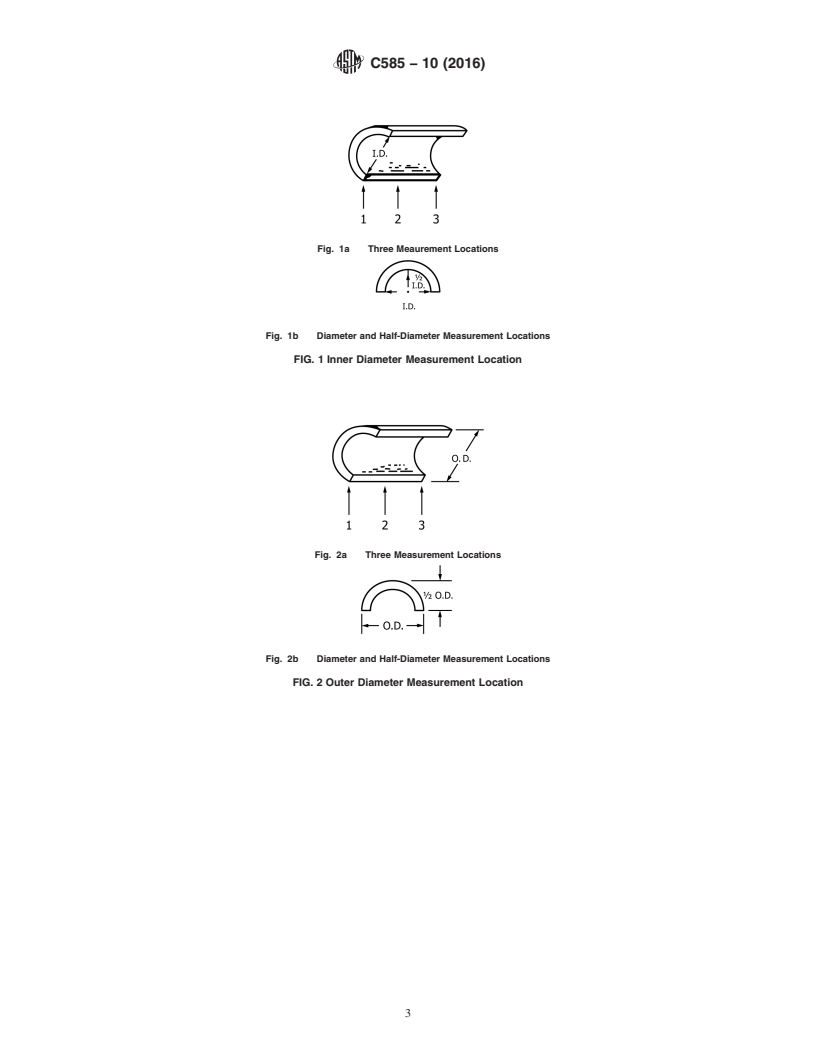
6.1.1.2 Half Sections—The diameter reported for each half-section shall be the average of six measurements taken at three
locations including two near the ends and one near the center (see Fig. 1a and Fig. 2a). Three of the six readings shall be taken
in the longitudinal plane of the flat, cut surface: the other three shall each be twice a half-diameter in the longitudinal plane at right
angles to that of the first three (see Fig. 1b and Fig. 2b).
6.1.1.3 Hinged Sections—The diameter reported for each hinged section shall be the average of four measurements taken at both
ends of the section (two per end) (see Fig. 3). The two measurements at each end shall be at right angles.
6.2 Recommended Inner Diameters:
6.2.1 Inner diameters and tolerances for nominal sizes of insulation for pipe are shown in Table 1, Table 7. Table 7a Table 9
and Table 9a.
6.2.2 Inner diameters and tolerances for nominal sizes of tubing are shown in Table 2, Table 8. Table 8a Table 10 and Table
10a.
6.3 Recommended Outer Diameters:
6.3.1 Outer diameters for nominal sizes of pipe are shown in Table 3 and Table 4, Table 7 and Table 9 and tubing in Table 5
and Table 6, Table 8, and Table 10. All Tables 3-10 are not for nesting purposes. When a pipe or tubing insulation product is to
be nested, it shall be so stated on order.
6.3.2 There are no maximum outer diameter tables provided for jacketing purposes because of the wide spread variations in the
outside diameters with their plus or minus tolerances.
NOTE 1—Previous versions of C585 contained Tables for jacketing purposes only. These tables have been removed from this practice with the inclusion
of variable outside diameters caused by the addition of outer diameter (OD) tolerances. It is recommended in order to calculate the maximum
circumferences for jacketing purposes, determine the pipe or tube insulation’s maximum outer diameters from the manufacturer. An alternative measure
for finding the jacketing stretch-out numbers is to look up the outer diameter for the pipe or tubing insulation from the tables; add the applicable plus
(+) outer diameter tolerance and twice the thickness of the jacketing to the insulation outer diameter number; multiply the added total times pī (3.14159)
to arrive at the maximum circumference; add the necessary longitudinal overlap dimension to the maximum circumference; and the calculated answer
will be the stretch-out requirement for cutting the outer jacketing to be applied over / around the pipe or tubing insulation’s OD.
NOTE 2—NPS (Nominal Pipe Size) is a dimensionless designator that has been substituted in the customary units section for the previous term inch
nominal pipe size.
NOTE 3—NTS (Nominal Tube Size) is a dimensionless designator that has been substituted in the customary units section for the previous term inch
nominal tube size.
NOTE 4—DN (Diameter Nominal) is a dimensionless designator that has been substituted in the customary units section for the previous term SI
(metric) system to describe millimeter nominal pipe or tube size.
7. Keywords
7.1 pipe thermal insulation diameter; pipe thermal insulation dimension; thermal insulating materials-pipe; thermal insulating
materials-tubing; thermal insulation; tubing thermal insulation diameter; tubing thermal insulation dimension
C585 − 10 (2016)
Fig. 1a Three Meaurement Locations
Fig. 1b Diameter and Half-Diameter Measurement Locations
FIG. 1 Inner Diameter Measurement Location
Fig. 2a Three Measurement Locations
Fig. 2b Diameter and Half-Diameter Measurement Locations
FIG. 2 Outer Diameter Measurement Location
C585 − 10 (2016)
FIG. 3 Hinged Section Measurement Location
TABLE 1 Nominal Pipe Sizes with Inner Diameters and Tolerances for
Calcium Silicate, Cellular Foam Plastics, Cellular Glass, Mineral Fiber, and Perlite Preformed Insulation
Customary and SI Units for Pipe Insulation
Tolerance
Outer Diameter Inner Diameter
NPS DN
Minus Plus
Note 2 Note 4
in. mm in. mm in. mm in. mm
⁄2 15 0.840 21.3 0.86 22 0 0 0.063 1.6
⁄4 20 1.050 26.7 1.07 27 0 0 0.063 1.6
1 25 1.315 33.4 1.33 34 0 0 0.063 1.6
1 ⁄4 32 1.660 42.2 1.68 43 0 0 0.063 1.6
1 ⁄2 40 1.900 48.3 1.92 49 0 0 0.063 1.6
2 50 2.375 60.3 2.41 61 0 0 0.094 2.4
2 ⁄2 65 2.875 73.0 2.91 74 0 0 0.094 2.4
3 80 3.500 88.9 3.53 90 0 0 0.094 2.4
3 ⁄2 90 4.000 101.6 4.03 102 0.031 0.8 0.094 2.4
4 100 4.500 114.3 4.53 115 0.031 0.8 0.094 2.4
4 ⁄2 115 5.000 127.0 5.03 128 0.031 0.8 0.094 2.4
5 125 5.563 141.4 5.64 143 0.031 0.8 0.094 2.4
6 150 6.625 168.3 6.70 170 0.031 0.8 0.094 2.4
7 175 7.625 193.7 7.70 196 0.031 0.8 0.094 2.4
8 200 8.625 219.1 8.70 221 0.031 0.8 0.094 2.4
9 225 9.625 244.5 9.70 246 0.031 0.8 0.094 2.4
10 250 10.750 273.0 10.83 275 0.031 0.8 0.094 2.4
11 275 11.750 298.4 11.83 300 0.031 0.8 0.094 2.4
12 300 12.750 323.8 12.84 326 0.063 1.6 0.094 2.4
14 350 14.000 355.6 14.09 358 0.063 1.6 0.156 4.0
C585 − 10 (2016)
TABLE 2 Nominal Tube Sizes with Inner Diameter and Tolerances for
Calcium Silicate, Cellular Foam Plastics, Cellular Glass, Mineral Fiber, and Perlite Preformed Insulation
Customary and SI Units for Tube Insulation
Tolerance
Outer Diameter Inner Diameter
NTS DN
Minus Plus
Note 3 Note 4
in. mm in. mm in. mm in. mm
⁄8 10 0.500 12.7 0.52 13 0 0 0.063 1.6
⁄2 15 0.625 15.9 0.64 16 0 0 0.063 1.6
⁄4 20 0.875 22.2 0.89 23 0 0 0.063 1.6
1 25 1.125 28.6 1.14 29 0 0 0.063 1.6
1 ⁄4 32 1.375 34.9 1.39 35 0 0 0.063 1.6
1 ⁄2 40 1.625 41.3 1.64 42 0 0 0.063 1.6
2 50 2.125 54.0 2.16 55 0 0 0.063 1.6
2 ⁄2 65 2.625 66.7 2.66 68 0 0 0.063 1.6
3 80 3.125 79.4 3.16 80 0 0 0.063 1.6
3 ⁄2 90 3.625 92.1 3.66 93 0 0 0.063 1.6
4 100 4.125 104.8 4.16 106 0.031 0.8 0.094 2.4
5 125 5.125 130.2 5.16 131 0.031 0.8 0.094 2.4
6 150 6.125 155.6 6.20 157 0.031 0.8 0.094 2.4
TABLE 3 Outer Diameters for Nominal Pipe Sizes and Nominal Wall Thickness on
Calcium Silicate, Cellular Foam Plastics, Cellular Glass, Mineral Fiber, and Perlite Preformed Insulation, inches
Pipe Customary Units for Insulation, Nominal Thickness
1 1 1 1
in. 1 1 ⁄2 2 2 ⁄2 3 3 ⁄2 4 4 ⁄2 5
NPS
Outer Diameter, in.
Note 2
⁄2 2.88 4.00 5.00 6.62 7.62 8.62 9.62 10.75 11.75
⁄4 2.88 4.00 5.00 6.62 7.62 8.62 9.62 10.75 11.75
1 3.50 4.50 5.56 6.62 7.62 8.62 9.62 10.75 11.75
1 ⁄4 3.50 5.00 5.56 6.62 7.62 8.62 9.62 10.75 11.75
1 ⁄2 4.00 5.00 6.62 7.62 8.62 9.62 10.75 11.75 12.75
2 4.50 5.56 6.62 7.62 8.62 9.62 10.75 11.75 12.75
2 ⁄2 5.00 6.62 7.62 8.62 9.62 10.75 11.75 12.75 14.00
3 5.56 6.62 7.62 8.62 9.62 10.75 11.75 12.75 14.00
3 ⁄2 6.62 7.62 8.62 9.62 10.75 11.75 12.75 12.75 14.00
4 6.62 7.62 8.62 9.62 10.75 11.75 12.75 14.00 15.00
4 ⁄2 7.62 8.62 9.62 10.75 11.75 12.75 14.00 14.00 15.00
5 7.62 8.62 9.62 10.75 11.75 12.75 14.00 15.00 16.00
6 8.62 9.62 10.75 11.75 12.75 14.00 15.00 16.00 17.00
7 . 10.75 11.75 12.75 14.00 15.00 16.00 17.00 18.00
8 . 11.75 12.75 14.00 15.00 16.00 17.00 18.00 19.00
9 . 12.75 14.00 15.00 16.00 17.00 18.00 19.00 20.00
10 . 14.00 15.00 16.00 17.00 18.00 19.00 20.00 21.00
11 . 15.00 16.00 17.00 18.00 19.00 20.00 21.00 22.00
12 . 16.00 17.00 18.00 19.00 20.00 21.00 22.00 23.00
14 . 17.00 18.00 19.00 20.00 21.00 22.00 23.00 24.00
TABLE 3a Outer Diameter Tolerances for
Calcium Silicate and Perlite Preformed Pipe and Tubing Insulation, inches
Outside Diameter (O.D.) Outside Diameters
of Insulation, inches Tolerances (O.D.), inches
2.88 to 6.62 ± 0.188
7.62 to 14.00 ± 0.250
15.00 to 20.00 ± 0.313
21.00 to 29.00 ± 0.375
30.00 and larger ± 0.438
TABLE 3b Outer Diameter Tolerances for
Cellular Foam Plastics, Cellular Glass, and Mineral Fiber Preformed Pipe and Tubing Insulation, inches
Outside Diameter (O.D.) Outside Diameters
of Insulation, inches Tolerances (O.D.), inches
2.88 to 6.62 ± 0.188
7.62 to 14.00 ± 0.250
15.00 to 20.00 ± 0.313
21.00 to 29.00 ± 0.375
30.00 and larger ± 0.438
C585 − 10 (2016)
TABLE 4 Outer Diameters for Nominal Pipe Sizes and Nominal Wall Thickness on
Calcium Silicate, Cellular Foam Plastics, Cellular Glass, Mineral Fiber, and Perlite Preformed Insulation, millimeters
Pipe Customary SI Units for Insulation, Nominal Thickness
DN mm 25 38 51 64 76 89 102 114 127
Note 4
Outer Diameter, mm
15 73 102 127 168 194 219 244 273 298
20 73 102 127 168 194 219 244 273 298
25 89 114 141 168 194 219 244 273 298
32 89 127 141 168 194 219 244 273 298
40 102 127 168 194 219 244 273 298 324
50 114 141 168 194 219 244 273 298 324
65 127 168 194 219 244 273 298 324 356
80 141 168 194 219 244 273 298 324 356
90 168 194 219 244 273 298 324 356 381
100 168 194 219 244 273 298
...
Questions, Comments and Discussion
Ask us and Technical Secretary will try to provide an answer. You can facilitate discussion about the standard in here.