


ASTM E741-11(2017)
(Test Method)Standard Test Method for Determining Air Change in a Single Zone by Means of a Tracer Gas Dilution
Standard Test Method for Determining Air Change in a Single Zone by Means of a Tracer Gas Dilution
SIGNIFICANCE AND USE
5.1 Effects of Air Change—Air change often accounts for a significant portion of the heating or air-conditioning load of a building. It also affects the moisture and contaminant balances in the building. Moisture-laden air passing through the building envelope can permit condensation and cause material degradation. An appropriate level of ventilation is required in all buildings; one should consult ASHRAE Standard 62 to determine the ventilation requirements of a building.
5.2 Prediction of Air Change—Air change depends on the size and distribution of air leakage sites, pressure differences induced by wind and temperature, mechanical system operation, and occupant behavior. Air change may be calculated from this information, however, many of the needed parameters are difficult to determine. Tracer gas testing permits direct measurement of air change.
5.3 Utility of Measurement—Measurements of air change provide useful information about ventilation and air leakage. Measurements in buildings with the ventilation system closed are used to determine whether natural air leakage rates are higher than specified. Measurements with the ventilation system in operation are used to determine whether the air change meets or exceeds requirements.
5.4 Known Conditions—Knowledge of the factors that affect air change makes measurement more meaningful. Relating building response to wind and temperature requires repetition of the test under varying meteorological conditions. Relating building response to the ventilation system or to occupant behavior requires controlled variation of these factors.
5.5 Applicability of Results—The values for air change obtained by the techniques used in this test method apply to the specific conditions prevailing at the time of the measurement. Air change values for the same building will differ if the prevailing wind and temperature conditions have changed, if the operation of the building is different, or if the envelope changes between m...
SCOPE
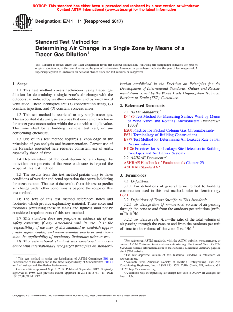
1.1 This test method covers techniques using tracer gas dilution for determining a single zone's air change with the outdoors, as induced by weather conditions and by mechanical ventilation. These techniques are: (1) concentration decay, (2) constant injection, and (3) constant concentration.
1.2 This test method is restricted to any single tracer gas. The associated data analysis assumes that one can characterize the tracer gas concentration within the zone with a single value. The zone shall be a building, vehicle, test cell, or any conforming enclosure.
1.3 Use of this test method requires a knowledge of the principles of gas analysis and instrumentation. Correct use of the formulas presented here requires consistent use of units, especially those of time.
1.4 Determination of the contribution to air change by individual components of the zone enclosure is beyond the scope of this test method.
1.5 The results from this test method pertain only to those conditions of weather and zonal operation that prevailed during the measurement. The use of the results from this test to predict air change under other conditions is beyond the scope of this test method.
1.6 The text of this test method references notes and footnotes which provide explanatory material. These notes and footnotes (excluding those in tables and figures) shall not be considered requirements of this test method.
1.7 This standard does not purport to address all of the safety concerns, if any, associated with its use. It is the responsibility of the user of this standard to establish appropriate safety, health, and environmental practices and determine the applicability of regulatory limitations prior to use.
1.8 This international standard was developed in accordance with internationally recognized principles on standardization established in the Decision on Principles for the Development of International Standards, Guides and Recommend...
General Information
Buy Standard
Standards Content (Sample)
NOTICE: This standard has either been superseded and replaced by a new version or withdrawn.
Contact ASTM International (www.astm.org) for the latest information
Designation: E741 − 11 (Reapproved 2017)
Standard Test Method for
Determining Air Change in a Single Zone by Means of a
Tracer Gas Dilution
This standard is issued under the fixed designation E741; the number immediately following the designation indicates the year of
original adoption or, in the case of revision, the year of last revision. A number in parentheses indicates the year of last reapproval. A
superscript epsilon (´) indicates an editorial change since the last revision or reapproval.
1. Scope ization established in the Decision on Principles for the
Development of International Standards, Guides and Recom-
1.1 This test method covers techniques using tracer gas
mendations issued by the World Trade Organization Technical
dilution for determining a single zone’s air change with the
Barriers to Trade (TBT) Committee.
outdoors, as induced by weather conditions and by mechanical
ventilation. These techniques are: (1) concentration decay, (2)
2. Referenced Documents
constant injection, and (3) constant concentration.
2.1 ASTM Standards:
1.2 This test method is restricted to any single tracer gas.
D4480 Test Method for Measuring Surface Wind by Means
The associated data analysis assumes that one can characterize
of Wind Vanes and Rotating Anemometers (Withdrawn
the tracer gas concentration within the zone with a single value.
1999)
The zone shall be a building, vehicle, test cell, or any
E260 Practice for Packed Column Gas Chromatography
conforming enclosure.
E631 Terminology of Building Constructions
1.3 Use of this test method requires a knowledge of the E779 Test Method for Determining Air Leakage Rate by Fan
principles of gas analysis and instrumentation. Correct use of
Pressurization
the formulas presented here requires consistent use of units, E1186 Practices for Air Leakage Site Detection in Building
especially those of time.
Envelopes and Air Barrier Systems
2.2 ASHRAE Documents:
1.4 Determination of the contribution to air change by
ASHRAE Handbook of Fundamentals Chapter 23
individual components of the zone enclosure is beyond the
ASHRAE Standard 62
scope of this test method.
1.5 The results from this test method pertain only to those
3. Terminology
conditions of weather and zonal operation that prevailed during
3.1 Definitions:
the measurement. The use of the results from this test to predict
3.1.1 For definitions of general terms related to building
air change under other conditions is beyond the scope of this
construction used in this test method, refer to Terminology
test method.
E631.
1.6 The text of this test method references notes and
3.2 Definitions of Terms Specific to This Standard:
footnotes which provide explanatory material. These notes and
3.2.1 air change flow, Q, n—the total volume of air passing
footnotes (excluding those in tables and figures) shall not be
through the zone to and from the outdoors per unit time (m /s,
3 3
considered requirements of this test method.
m /h, ft /h).
1.7 This standard does not purport to address all of the
3.2.2 air change rate, A, n—the ratio of the total volume of
safety concerns, if any, associated with its use. It is the
air passing through the zone to and from the outdoors per unit
responsibility of the user of this standard to establish appro-
of time to the volume of the zone (1/s, 1/h).
priate safety, health, and environmental practices and deter-
mine the applicability of regulatory limitations prior to use.
For referenced ASTM standards, visit the ASTM website, www.astm.org, or
1.8 This international standard was developed in accor-
contact ASTM Customer Service at service@astm.org. For Annual Book of ASTM
dance with internationally recognized principles on standard-
Standards volume information, refer to the standard’s Document Summary page on
the ASTM website.
The last approved version of this historical standard is referenced on
This test method is under the jurisdiction of ASTM Committee E06 on www.astm.org.
Performance of Buildings and is the direct responsibility of Subcommittee E06.41 Available from American Society of Heating, Refrigerating, and Air-
on Air Leakage and Ventilation Performance. Conditioning Engineers, Inc. (ASHRAE), 1791 Tullie Circle, NE, Atlanta, GA
Current edition approved Sept. 1, 2017. Published September 2017. Originally 30329, http://www.ashrae.org.
approved in 1980. Last previous edition approved in 2011 as E741 – 11. DOI: A common way of expressing air change rate units is ACH = air changes per
10.1520/E0741-11R17. hour = 1 ⁄h.
Copyright © ASTM International, 100 Barr Harbor Drive, PO Box C700, West Conshohocken, PA 19428-2959. United States
E741 − 11 (2017)
3.2.3 envelope, n—the system of barriers between a condi-
i = pertaining to time or location.
tioned building zone and the outdoors.
inj = pertaining to the injection period.
lower = lower limit.
3.2.3.1 Discussion—This includes exterior doors, windows,
meas = pertaining to the measurement.
roofs, walls, floors and ductwork. It excludes interior
mix = pertaining to the mixing period.
partitions, ducts, and so forth, that separate conditioned zones.
precis = pertaining to precision.
3.2.4 tracer gas, n—a gas that is mixed with air and
rep = pertaining to replicates.
measured in very small concentrations in order to study air
sample = pertaining to a discrete tracer gas or air sample.
movement.
target = pertaining to the desired level of tracer gas.
test = pertaining to the test period.
3.2.5 tracer gas analyzer, n—a device used to measure the
twt = weighted according to tracer gas flow.
concentration of tracer gas in an air sample.
tracer = pertaining to the tracer gas.
3.2.6 tracer gas concentration, C, n—the ratio of the quan-
upper = upper limit.
tity of tracer gas in air to the quantity of that air (moles/mole
vol = pertaining to the volume of the zone.
3 3
or m /m ).
zone = pertaining to the zone under study.
1 = first occurrence under discussion.
3.2.7 single zone, n—a space or set of spaces wherein the
2 = last occurrence under discussion.
concentration of a tracer gas is maintained uniformly through-
out and that only exchanges air with the outside.
3.3.4 Other Notations:
3.2.7.1 Discussion—Multizone buildings are difficult to
treat as single zones and meet the uniformity of tracer gas
Δt = time interval between periodic samples.
concentration required in this test method. Single zones within
(t) = function of time.
multizone buildings are difficult to isolate such that they
(t, i) = function of time, t, and location, i.
exchange air only with the outside and not to other zones
t(n, 1−α) = t-distribution value for n degrees of freedom and
within the building via ventilation ducts, electrical conduits,
a two-sided probability of α.
elevator shafts, stairs, and other pathways.
3.3 Symbols:
4. Summary of Test Method
3.3.1 Variables:
4.1 This test method uses the measurement of tracer gas
dilution to determine air change within a building or other
A = air change rate (1/s, 1/h).
enclosure that is characterized as a single zone. The measure-
C = concentration (dimensionless).
ment of the concentration, and sometimes the volume rate of
CONF = confidence limit value (units of the variable mea-
the tracer gas that is injected into the zone, allows calculation
sured).
of the volume rate of outgoing air from the zone. From this,
d = desired precision (dimensionless).
one can infer the volume rate of incoming air. Three techniques
ESE = estimated standard error.
are presented: (1) concentration decay, (2) constant injection,
i = location number.
and (3) constant concentration. Each technique employs spe-
k = constant.
cific tracer gas injection and sampling strategies. Other tech-
n = number of data points.
niques exist but are beyond the scope of this test method. Table
N = number of sampling locations in the zone.
3 3 3
1 summarizes the three techniques.
Q = flow (m /s, m /h, ft /h).
s = sample standard deviation (units of the variable
4.2 Choice of Technique—In choosing a technique for
estimated).
measuring air change, consider the quantity to be measured, the
t = a specific time (s, h).
comparative capabilities of the techniques, and the complexity
T = a period of time (s, h).
of the required equipment.
3 3
V = volume (m , ft ).
4.2.1 Air Change Quantity to Be Measured—Choose be-
α = probability (dimensionless).
tween direct measurement of air change rate or air change flow.
ε = error (units of the variable estimated).
Conversions between rate and flow and vice versa are subject
ν = coefficient of variation (dimensionless).
to the precision and bias of the measurement of the zone
3.3.2 Superscripts:
volume. To obtain air change rate directly, use the tracer gas
decay technique. To obtain air change flow, use the constant
' = value at the end of the test.
injection or constant concentration techniques.
− = mean value.
3.3.3 Subscripts:
5. Significance and Use
A = pertaining to air change rate.
5.1 Effects of Air Change—Air change often accounts for a
avg = average.
significant portion of the heating or air-conditioning load of a
bias = pertaining to bias.
building. It also affects the moisture and contaminant balances
C = pertaining to concentration.
in the building. Moisture-laden air passing through the building
est = estimated.
envelope can permit condensation and cause material degrada-
GA = pertaining to the gas analyzer.
tion. An appropriate level of ventilation is required in all
E741 − 11 (2017)
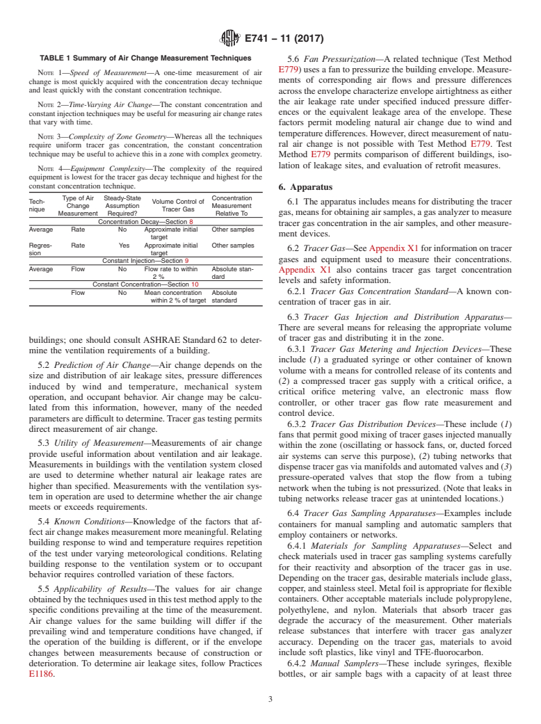
TABLE 1 Summary of Air Change Measurement Techniques
5.6 Fan Pressurization—A related technique (Test Method
E779) uses a fan to pressurize the building envelope. Measure-
NOTE 1—Speed of Measurement—A one-time measurement of air
ments of corresponding air flows and pressure differences
change is most quickly acquired with the concentration decay technique
and least quickly with the constant concentration technique.
across the envelope characterize envelope airtightness as either
the air leakage rate under specified induced pressure differ-
NOTE 2—Time-Varying Air Change—The constant concentration and
ences or the equivalent leakage area of the envelope. These
constant injection techniques may be useful for measuring air change rates
that vary with time.
factors permit modeling natural air change due to wind and
temperature differences. However, direct measurement of natu-
NOTE 3—Complexity of Zone Geometry—Whereas all the techniques
ral air change is not possible with Test Method E779. Test
require uniform tracer gas concentration, the constant concentration
technique may be useful to achieve this in a zone with complex geometry.
Method E779 permits comparison of different buildings, iso-
lation of leakage sites, and evaluation of retrofit measures.
NOTE 4—Equipment Complexity—The complexity of the required
equipment is lowest for the tracer gas decay technique and highest for the
constant concentration technique.
6. Apparatus
Type of Air Steady-State Concentration
Tech- Volume Control of
6.1 The apparatus includes means for distributing the tracer
Change Assumption Measurement
nique Tracer Gas
gas, means for obtaining air samples, a gas analyzer to measure
Measurement Required? Relative To
Concentration Decay—Section 8
tracer gas concentration in the air samples, and other measure-
Average Rate No Approximate initial Other samples
ment devices.
target
Regres- Rate Yes Approximate initial Other samples
6.2 Tracer Gas—See Appendix X1 for information on tracer
sion target
gases and equipment used to measure their concentrations.
Constant Injection—Section 9
Average Flow No Flow rate to within Absolute stan-
Appendix X1 also contains tracer gas target concentration
2 % dard
levels and safety information.
Constant Concentration—Section 10
Flow No Mean concentration Absolute 6.2.1 Tracer Gas Concentration Standard—A known con-
within 2 % of target standard
centration of tracer gas in air.
6.3 Tracer Gas Injection and Distribution Apparatus—
There are several means for releasing the appropriate volume
of tracer gas and distributing it in the zone.
buildings; one should consult ASHRAE Standard 62 to deter-
6.3.1 Tracer Gas Metering and Injection Devices—These
mine the ventilation requirements of a building.
include (1) a graduated syringe or other container of known
5.2 Prediction of Air Change—Air change depends on the
volume with a means for controlled release of its contents and
size and distribution of air leakage sites, pressure differences
(2) a compressed tracer gas supply with a critical orifice, a
induced by wind and temperature, mechanical system
critical orifice metering valve, an electronic mass flow
operation, and occupant behavior. Air change may be calcu-
controller, or other tracer gas flow rate measurement and
lated from this information, however, many of the needed
control device.
parameters are difficult to determine. Tracer gas testing permits
6.3.2 Tracer Gas Distribution Devices—These include (1)
direct measurement of air change.
fans that permit good mixing of tracer gases injected manually
5.3 Utility of Measurement—Measurements of air change
within the zone (oscillating or hassock fans, or, ducted forced
provide useful information about ventilation and air leakage.
air systems can serve this purpose), (2) tubing networks that
Measurements in buildings with the ventilation system closed
dispense tracer gas via manifolds and automated valves and (3)
are used to determine whether natural air leakage rates are
pressure-operated valves that stop the flow from a tubing
higher than specified. Measurements with the ventilation sys-
network when the tubing is not pressurized. (Note that leaks in
tem in operation are used to determine whether the air change
tubing networks release tracer gas at unintended locations.)
meets or exceeds requirements.
6.4 Tracer Gas Sampling Apparatuses—Examples include
5.4 Known Conditions—Knowledge of the factors that af-
containers for manual sampling and automatic samplers that
fect air change makes measurement more meaningful. Relating
employ containers or networks.
building response to wind and temperature requires repetition
6.4.1 Materials for Sampling Apparatuses—Select and
of the test under varying meteorological conditions. Relating
check materials used in tracer gas sampling systems carefully
building response to the ventilation system or to occupant
for their reactivity and absorption of the tracer gas in use.
behavior requires controlled variation of these factors.
Depending on the tracer gas, desirable materials include glass,
copper, and stainless steel. Metal foil is appropriate for flexible
5.5 Applicability of Results—The values for air change
obtained by the techniques used in this test method ap
...
This document is not an ASTM standard and is intended only to provide the user of an ASTM standard an indication of what changes have been made to the previous version. Because
it may not be technically possible to adequately depict all changes accurately, ASTM recommends that users consult prior editions as appropriate. In all cases only the current version
of the standard as published by ASTM is to be considered the official document.
Designation: E741 − 11 E741 − 11 (Reapproved 2017)
Standard Test Method for
Determining Air Change in a Single Zone by Means of a
Tracer Gas Dilution
This standard is issued under the fixed designation E741; the number immediately following the designation indicates the year of
original adoption or, in the case of revision, the year of last revision. A number in parentheses indicates the year of last reapproval. A
superscript epsilon (´) indicates an editorial change since the last revision or reapproval.
1. Scope
1.1 This test method covers techniques using tracer gas dilution for determining a single zone’s air change with the outdoors,
as induced by weather conditions and by mechanical ventilation. These techniques are: (1) concentration decay, (2) constant
injection, and (3) constant concentration.
1.2 This test method is restricted to any single tracer gas. The associated data analysis assumes that one can characterize the
tracer gas concentration within the zone with a single value. The zone shall be a building, vehicle, test cell, or any conforming
enclosure.
1.3 Use of this test method requires a knowledge of the principles of gas analysis and instrumentation. Correct use of the
formulas presented here requires consistent use of units, especially those of time.
1.4 Determination of the contribution to air change by individual components of the zone enclosure is beyond the scope of this
test method.
1.5 The results from this test method pertain only to those conditions of weather and zonal operation that prevailed during the
measurement. The use of the results from this test to predict air change under other conditions is beyond the scope of this test
method.
1.6 The text of this test method references notes and footnotes which provide explanatory material. These notes and footnotes
(excluding those in tables and figures) shall not be considered requirements of this test method.
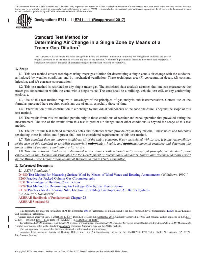
1.7 This standard does not purport to address all of the safety concerns, if any, associated with its use. It is the responsibility
of the user of this standard to establish appropriate safety safety, health, and healthenvironmental practices and determine the
applicability of regulatory limitations prior to use.
1.8 This international standard was developed in accordance with internationally recognized principles on standardization
established in the Decision on Principles for the Development of International Standards, Guides and Recommendations issued
by the World Trade Organization Technical Barriers to Trade (TBT) Committee.
2. Referenced Documents
2.1 ASTM Standards:
D4480 Test Method for Measuring Surface Wind by Means of Wind Vanes and Rotating Anemometers (Withdrawn 1999)
E260 Practice for Packed Column Gas Chromatography
E631 Terminology of Building Constructions
E779 Test Method for Determining Air Leakage Rate by Fan Pressurization
E1186 Practices for Air Leakage Site Detection in Building Envelopes and Air Barrier Systems
2.2 ASHRAE Documents:
ASHRAE Handbook of Fundamentals Chapter 23
ASHRAE Standard 62
This test method is under the jurisdiction of ASTM Committee E06 on Performance of Buildings and is the direct responsibility of Subcommittee E06.41 on Air Leakage
and Ventilation Performance.
Current edition approved Sept. 1, 2011Sept. 1, 2017. Published October 2011September 2017. Originally approved in 1980. Last previous edition approved in 20062011
ε1
as E741 – 00 (2006)E741 – 11. . DOI: 10.1520/E0741-11.10.1520/E0741-11R17.
For referenced ASTM standards, visit the ASTM website, www.astm.org, or contact ASTM Customer Service at service@astm.org. For Annual Book of ASTM Standards
volume information, refer to the standard’sstandard’s Document Summary page on the ASTM website.
The last approved version of this historical standard is referenced on www.astm.org.
Available from American Society of Heating, Refrigerating, and Air-Conditioning Engineers, Inc. (ASHRAE), 1791 Tullie Circle, NE, Atlanta, GA 30329,
http://www.ashrae.org.
Copyright © ASTM International, 100 Barr Harbor Drive, PO Box C700, West Conshohocken, PA 19428-2959. United States
E741 − 11 (2017)
3. Terminology
3.1 Definitions:
3.1.1 For definitions of general terms related to building construction used in this test method, refer to Terminology E631.
3.2 Definitions of Terms Specific to This Standard:
3 3
3.2.1 air change flow, Q, n—the total volume of air passing through the zone to and from the outdoors per unit time (m /s, m /h,
ft /h).
3.2.2 air change rate, A, n—the ratio of the total volume of air passing through the zone to and from the outdoors per unit of
time to the volume of the zone (1/s, 1/h).
3.2.3 envelope, n—the system of barriers between a conditioned building zone and the outdoors.
A common way of expressing air change rate units is ACH = air changes per hour = 1 ⁄h.
3.2.3.1 Discussion—
This includes exterior doors, windows, roofs, walls, floors and ductwork. It excludes interior partitions, ducts, and so forth, that
separate conditioned zones.
3.2.4 tracer gas, n—a gas that is mixed with air and measured in very small concentrations in order to study air movement.
3.2.5 tracer gas analyzer, n—a device used to measure the concentration of tracer gas in an air sample.
3.2.6 tracer gas concentration, C, n—the ratio of the quantity of tracer gas in air to the quantity of that air (moles/mole or
3 3
m /m ).
3.2.7 single zone, n—a space or set of spaces wherein the concentration of a tracer gas is maintained uniformly throughout and
that only exchanges air with the outside.
3.2.7.1 Discussion—
Multizone buildings are difficult to treat as single zones and meet the uniformity of tracer gas concentration required in this test
method. Single zones within multizone buildings are difficult to isolate such that they exchange air only with the outside and not
to other zones within the building via ventilation ducts, electrical conduits, elevator shafts, stairs, and other pathways.
3.3 Symbols:
3.3.1 Variables:
A = air change rate (1/s, 1/h).
C = concentration (dimensionless).
CONF = confidence limit value (units of the variable measured).
d = desired precision (dimensionless).
ESE = estimated standard error.
i = location number.
k = constant.
n = number of data points.
N = number of sampling locations in the zone.
3 3 3
Q = flow (m /s, m /h, ft /h).
s = sample standard deviation (units of the variable estimated).
t = a specific time (s, h).
T = a period of time (s, h).
3 3
V = volume (m , ft ).
α = probability (dimensionless).
ε = error (units of the variable estimated).
ν = coefficient of variation (dimensionless).
3.3.2 Superscripts:
' = value at the end of the test.
− = mean value.
3.3.3 Subscripts:
A = pertaining to air change rate.
E741 − 11 (2017)
avg = average.
bias = pertaining to bias.
C = pertaining to concentration.
est = estimated.
GA = pertaining to the gas analyzer.
i = pertaining to time or location.
inj = pertaining to the injection period.
lower = lower limit.
meas = pertaining to the measurement.
mix = pertaining to the mixing period.
precis = pertaining to precision.
rep = pertaining to replicates.
sample = pertaining to a discrete tracer gas or air sample.
target = pertaining to the desired level of tracer gas.
test = pertaining to the test period.
twt = weighted according to tracer gas flow.
tracer = pertaining to the tracer gas.
upper = upper limit.
vol = pertaining to the volume of the zone.
zone = pertaining to the zone under study.
1 = first occurrence under discussion.
2 = last occurrence under discussion.
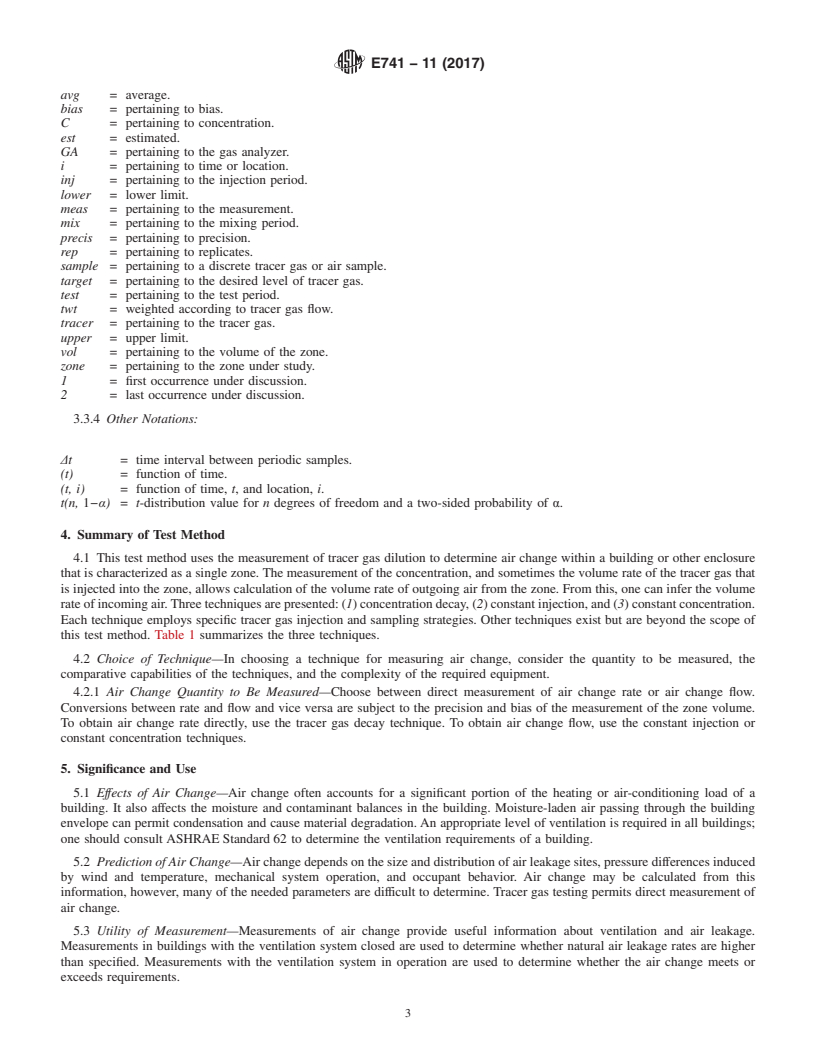
3.3.4 Other Notations:
Δt = time interval between periodic samples.
(t) = function of time.
(t, i) = function of time, t, and location, i.
t(n, 1−α) = t-distribution value for n degrees of freedom and a two-sided probability of α.
4. Summary of Test Method
4.1 This test method uses the measurement of tracer gas dilution to determine air change within a building or other enclosure
that is characterized as a single zone. The measurement of the concentration, and sometimes the volume rate of the tracer gas that
is injected into the zone, allows calculation of the volume rate of outgoing air from the zone. From this, one can infer the volume
rate of incoming air. Three techniques are presented: (1) concentration decay, (2) constant injection, and (3) constant concentration.
Each technique employs specific tracer gas injection and sampling strategies. Other techniques exist but are beyond the scope of
this test method. Table 1 summarizes the three techniques.
4.2 Choice of Technique—In choosing a technique for measuring air change, consider the quantity to be measured, the
comparative capabilities of the techniques, and the complexity of the required equipment.
4.2.1 Air Change Quantity to Be Measured—Choose between direct measurement of air change rate or air change flow.
Conversions between rate and flow and vice versa are subject to the precision and bias of the measurement of the zone volume.
To obtain air change rate directly, use the tracer gas decay technique. To obtain air change flow, use the constant injection or
constant concentration techniques.
5. Significance and Use
5.1 Effects of Air Change—Air change often accounts for a significant portion of the heating or air-conditioning load of a
building. It also affects the moisture and contaminant balances in the building. Moisture-laden air passing through the building
envelope can permit condensation and cause material degradation. An appropriate level of ventilation is required in all buildings;
one should consult ASHRAE Standard 62 to determine the ventilation requirements of a building.
5.2 Prediction of Air Change—Air change depends on the size and distribution of air leakage sites, pressure differences induced
by wind and temperature, mechanical system operation, and occupant behavior. Air change may be calculated from this
information, however, many of the needed parameters are difficult to determine. Tracer gas testing permits direct measurement of
air change.
5.3 Utility of Measurement—Measurements of air change provide useful information about ventilation and air leakage.
Measurements in buildings with the ventilation system closed are used to determine whether natural air leakage rates are higher
than specified. Measurements with the ventilation system in operation are used to determine whether the air change meets or
exceeds requirements.
E741 − 11 (2017)
TABLE 1 Summary of Air Change Measurement Techniques
NOTE 1—Speed of Measurement—A one-time measurement of air
change is most quickly acquired with the concentration decay technique
and least quickly with the constant concentration technique.
NOTE 2—Time-Varying Air Change—The constant concentration and
constant injection techniques may be useful for measuring air change rates
that vary with time.
NOTE 3—Complexity of Zone Geometry—Whereas all the techniques
require uniform tracer gas concentration, the constant concentration
technique may be useful to achieve this in a zone with complex geometry.
NOTE 4—Equipment Complexity—The complexity of the required
equipment is lowest for the tracer gas decay technique and highest for the
constant concentration technique.
Type of Air Steady-State Concentration
Tech- Volume Control of
Change Assumption Measurement
nique Tracer Gas
Measurement Required? Relative To
Concentration Decay—Section 8
Average Rate No Approximate ini- Other samples
tial target
Average Rate No Approximate initial Other samples
target
Regres- Rate Yes Approximate initial Other samples
sion target
Constant Injection—Section 9
Average Flow No Flow rate to within Absolute stan-
2 % dard
Constant Concentration—Section 10
Flow No Mean concentration Absolute
within 2 % of target standard
5.4 Known Conditions—Knowledge of the factors that affect air change makes measurement more meaningful. Relating
building response to wind and temperature requires repetition of the test under varying meteorological conditions. Relating
building response to the ventilation system or to occupant behavior requires controlled variation of these factors.
5.5 Applicability of Results—The values for air change obtained by the techniques used in this test method apply to the specific
conditions prevailing at the time of the measurement. Air change values for the same building will differ if the prevailing wind
and temperature conditions have changed, if the operation of the building is different, or if the envelope changes between
measurements because of construction or deterioration. To determine air leakage sites, follow PracticePractices E1186.
5.6 Fan Pressurization—A related technique (Test Method E779) uses a fan to pressurize the building envelope. Measurements
of corresponding air flows and pressure differences across the envelope characterize envelope airtightness as either the air leakage
rate under specified induced pressure differences or the equivalent leakage area of the envelope. These factors permit modeling
natural air change due to wind and temperature differences. However, direct measurement of natural air change is not possible with
Test Method E779. Test Method E779 permits comparison of different buildings, isolation of leakage sites, and evaluation of
retrofit measures.
6. Apparatus
6.1 The apparatus includes means for distributing the tracer gas, means for obtaining air samples, a gas analyzer to measure
tracer gas concentration in the air samples, and other measurement devices.
6.2 Tracer Gas—See Appendix X1 for information on tracer gases and equipment used to measure their concentrations.
Appendix X1 also contains tracer gas target concentration levels and safety information.
6.2.1 Tracer Gas Concentration Standard—A known concentration of tracer gas in air.
6.3 Tracer Gas Injection and Distribution Apparatus—There are several means for releasing the appropriate volume of tracer
gas and distributing it in the zone.
6.3.1 Tracer Gas Metering and Injection Devices—These include (1) a graduated syringe or other container of known volume
with a means for controlled release of its contents and (2) a compressed tracer gas supply with a critical orifice, a critical orifice
metering valve, an electronic mass flow controller, or other tracer gas flow rate measurement and control device.
6.3.2 Tracer Gas Distribution Devices—These include (1) fans that permit good mixing of tracer gases injected man
...
Questions, Comments and Discussion
Ask us and Technical Secretary will try to provide an answer. You can facilitate discussion about the standard in here.