


ASTM D2625-94(2015)
(Test Method)Standard Test Method for Endurance (Wear) Life and Load-Carrying Capacity of Solid Film Lubricants (Falex Pin and Vee Method)
Standard Test Method for Endurance (Wear) Life and Load-Carrying Capacity of Solid Film Lubricants (Falex Pin and Vee Method)
SIGNIFICANCE AND USE
5.1 This test method differentiates between bonded solid lubricants with respect to their wear life and load-carrying capacity. If the test conditions are changed, wear life may change and relative ratings of the bonded solid film lubricants may be different.
SCOPE
1.1 This test method (see Note 1) covers the determination of the endurance (wear) life and load-carrying capacity of dry solid film lubricants in sliding steel-on-steel applications.
Note 1: Reference may be made to Coordinating Research Council, Inc. (CRC) Report No. 419, “Development of Research Technique for Measuring Wear Life of Bonded Solid Lubricant Coatings for Airframes, Using the Falex Tester.” See also Military Specification MIL-L-8937 (ASG), Jan. 22, 1963, and Methods 3807 and 3812 of Federal Test Method 791a.
1.2 The values stated in SI units are to be regarded as the standard except where equipment is supplied using inch-pound units and would then be regarded as standard. The metric equivalents of inch-pound units given in such cases in the body of the standard may be approximate.
1.3 This standard does not purport to address all of the safety concerns, if any, associated with its use. It is the responsibility of the user of this standard to establish appropriate safety and health practices and determine the applicability of regulatory limitations prior to use.
General Information
Buy Standard
Standards Content (Sample)
NOTICE: This standard has either been superseded and replaced by a new version or withdrawn.
Contact ASTM International (www.astm.org) for the latest information
Designation: D2625 − 94 (Reapproved 2015)
Standard Test Method for
Endurance (Wear) Life and Load-Carrying Capacity of Solid
Film Lubricants (Falex Pin and Vee Method)
This standard is issued under the fixed designation D2625; the number immediately following the designation indicates the year of
original adoption or, in the case of revision, the year of last revision.Anumber in parentheses indicates the year of last reapproval.A
superscript epsilon (´) indicates an editorial change since the last revision or reapproval.
This standard has been approved for use by agencies of the U.S. Department of Defense.
1. Scope MIL-P-16232FPhosphate Coatings, Heavy, Manganese or
Zinc Base (for Ferrous Metals)
1.1 This test method (see Note 1) covers the determination
2.3 Other Standards:
of the endurance (wear) life and load-carrying capacity of dry
42USC7671aClean Air Act Amendments of 1990
solid film lubricants in sliding steel-on-steel applications.
Federal Test Method 791aMethods3807 and3812
NOTE 1—Reference may be made to Coordinating Research Council,
Inc. (CRC) Report No. 419, “Development of Research Technique for
3. Terminology
Measuring Wear Life of Bonded Solid Lubricant Coatings forAirframes,
3.1 Definitions:
Using the Falex Tester.” See also Military Specification MIL-L-8937
(ASG), Jan. 22, 1963, and Methods3807 and3812 of Federal Test
3.1.1 dry solid film lubricants—dry coatings consisting of
Method 791a.
lubricating powders in a solid matrix bonded to one or both
1.2 The values stated in SI units are to be regarded as the surfaces to be lubricated.
standardexceptwhereequipmentissuppliedusinginch-pound
3.2 Definitions of Terms Specific to This Standard:
units and would then be regarded as standard. The metric
3.2.1 direct load, n—theloadthatisappliedlinearly,bisect-
equivalentsofinch-poundunitsgiveninsuchcasesinthebody
ing the angle of the vee block corrected to either the 800lbf
of the standard may be approximate.
(3550N) gauge reference or the 3000lbf (13300N) gauge
1.3 This standard does not purport to address all of the
reference.
safety concerns, if any, associated with its use. It is the 3.2.1.1 Discussion—This load is equivalent to the true load
responsibility of the user of this standard to establish appro-
times the cos 42°.
priate safety and health practices and determine the applica-
3.2.2 endurance (wear) life—the length of test time before
bility of regulatory limitations prior to use.
failure under a constant loaded condition, in minutes, in which
the applied test lubricant performs its function.
2. Referenced Documents
3.2.3 gauge load, n—the value obtained from the gauge
2.1 ASTM Standards:
while running the test after being corrected to the standard
B16/B16MSpecification for Free-Cutting Brass Rod, Bar
curve using the calibration procedure for the 4500 lbf
and Shapes for Use in Screw Machines
(20000N) reference gauge.
F22Test Method for Hydrophobic Surface Films by the
3.2.3.1 Discussion—Thegaugereadingisirrespectiveofthe
Water-Break Test
particulargaugeused,andcorrectionsaremadebycomparison
2.2 U.S. Military Specifications:
totheBrinellballimpressiondiametersonastandardreference
MIL-L-8937
copper test coupon with a Rockwell hardness range of HB37
to HB39. An electronic calibration instrument is available
1 which can be used in place of the copper coupon.
This test method is under the jurisdiction of ASTM Committee D02 on
Petroleum Products, Liquid Fuels, and Lubricants and is the direct responsibility of
Subcommittee D02.L0.05 on Solid Lubricants.
CurrenteditionapprovedJuly1,2015.PublishedJuly2015.Originallyapproved AvailablefromU.S.GovernmentPrintingOfficeSuperintendentofDocuments,
in 1967. Last previous edition approved in 2010 as D2625–94 (2010). DOI: 732 N. Capitol St., NW, Mail Stop: SDE, Washington, DC 20401, http://
10.1520/D2625-94R15. www.access.gpo.gov.
2 5
For referenced ASTM standards, visit the ASTM website, www.astm.org, or Trademark of and available from Falex Corp., 1020Airpark Dr., Sugar Grove,
contact ASTM Customer Service at service@astm.org. For Annual Book of ASTM IL 60554. A new model of the Falex Pin and Vee Block Test Machine has been
Standards volume information, refer to the standard’s Document Summary page on available since 1983. Certain operating procedures are different for this new model.
the ASTM website. Consult instruction manual of machine for this information. If you are aware of
Available from Standardization Documents Order Desk, DODSSP, Bldg. 4, alternative suppliers, please provide this information to ASTM International
Section D, 700 Robbins Ave., Philadelphia, PA 19111-5098, http:// Headquarters.Your comments will receive careful consideration at a meeting of the
dodssp.daps.dla.mil. responsible technical committee, which you may attend.
Copyright © ASTM International, 100 Barr Harbor Drive, PO Box C700, West Conshohocken, PA 19428-2959. United States
D2625 − 94 (2015)
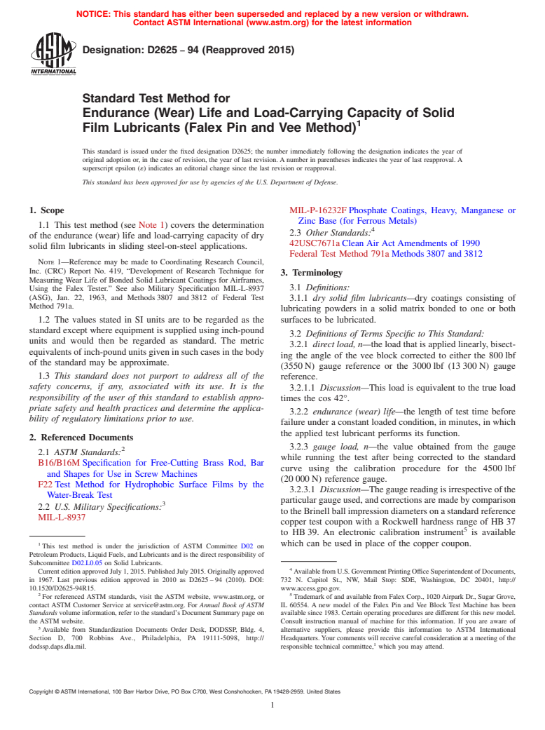
FIG. 1 Schematic Diagram of Falex Pin and Vee Block Test Machine
3.2.4 load carrying capacity—the highest indicated load 6.2.1 Standardized Test Coupon, soft, annealed copper HB
sustained for a minimum of 1min. 37/39.
6.2.2 Allen Screw, with attached 10mm Brinell ball.
4. Summary of Test Method
6.2.3 Back-up Plug.
4.1 The endurance test (Procedure A) consists of running
6.2.4 Brinell Microscope, or equivalent.
two stationary steel vee block specimens loaded to a predeter-
6.2.5 Rule, steel, 150mm (6in.) long.
mined value against a rotating steel pin specimen. The endur-
6.2.6 Timer, graduated in minutes and seconds.
ance (wear) life is determined when the torque increases by
6.3 Required for Application of Dry Solid Film Lubricants
10in.·lbf (1.13N·m).
(see Annex A1):
4.2 The load-carrying capacity test (Procedure B) consists
6.3.1 Desiccator, for storing test parts. The bottom of the
of running two stationary steel vee block specimens against a
desiccator shall be filled with desiccant to maintain approxi-
rotating steel pin, increasing the load on the pin until a sharp
mately 50% relative humidity. (Not required if parts can be
increase (10in.·lbf (1.13N·m)) in steady-state torque or pin
stored in a fume-free room at 50% 6 5% relative humidity.)
breakage is experienced. Prior to both tests, the solid film
6.3.2 Forced-Circulation Oven, capable of maintaining a
lubricant is deposited on the surfaces of the test specimens.
temperature of 149°C 6 5°C (300°F 6 10°F).
5. Significance and Use
6.3.3 Micrometer, reading 0 to 25mm 6 0.0025mm (0in.
to 1 6 0.0001in.), with a one-ball anvil.
5.1 This test method differentiates between bonded solid
6.3.4 Vapor Degreasing Bath.
lubricants with respect to their wear life and load-carrying
capacity. If the test conditions are changed, wear life may
7. Reagents and Materials
change and relative ratings of the bonded solid film lubricants
may be different.
7.1 Required for Procedures A and B:
7.1.1 Eight Standard Vee Blocks, 96° 6 1° angle, heat
6. Apparatus
9 9
treated to 1.24×10 Pa to 1.38×10 Pa (180000psi to
6.1 Falex Pin and Vee Block Test Machine, illustrated in
200000psi)tensilestrength;orstandardcoinedveeblocks,96
Fig. 1 and Fig. 2.
6 1° angle, of AISI C-1137 steel as an alternative, with a
6.1.1 Load Gauge, 4500lbf (20000N) range, or 3000lbf
Rockwell hardness of HRC 20 to 24 and surface finish of
(13300N) direct-reading gauge. An 800lbf (3550N) direct- −7 −7
1.3×10 mto2.5×10 m (5µin. to 10µin.), rms.
reading load gauge may be used for ProcedureA, but does not 5
7.1.2 Four Standard Test Pins, 6.35mm ( ⁄4in.) outside
have a high enough load range for Procedure B.
diameterby31.75mm(1 ⁄4in.)long,heattreatedto1.24×10
NOTE 2—Primary figures for loads are shown for the 4500lbf Pa to 1.38×10 Pa (180000psi to 200000psi) ultimate
(20000N) gauge. Equivalent readings on either 800lbf or 3000lbf
hardness; or Standard No. 8 Pins of AISI 3135 steel as an
(3550N or 13300N) direct-reading gauges are shown in parentheses and
alternative, with a hardness of HRB 87 to 91, on a ground, flat
can be obtained from the curve in Fig. 3.
surface (or approximately HRB 80 to 83 on the round), and a
−7 −7
6.1.2 Optional—An automatic cutoff, torque recorder, and
surface finish of 1.3×10 mto2.5×10 m (5µin. to
timer may be used in place of the standard indicating torque
10µin.) rms.
gauge.
7.1.3 Locking (Shear) Pin, ⁄2 H Brass, conforming to
6.2 Required for Calibration of Load Gauge: Specification B16/B16M.
D2625 − 94 (2015)
FIG. 1 Digital Pin and Vee Block Test Machine (continued)
FIG. 2 Exploded View of Vee Blocks and Journal Arrangement,
Falex Pin and Vee Block Test Machine
7.2 Required for Application of Dry Solid Film Lubricant
(see Annex A1):
7.2.1 Phosphate Coating, manganese, conforming to Mili-
tary Specification MIL-P-16232F, Type M, Class 3 controlled
2 2
to a coating weight of 16g⁄m to 22g⁄m .
NOTE 3—Lack of rigid control of the phosphate coating weight can
significantly impact the data scatter. A film controlled to the minimum
range is preferred over the uncontrolled standard heavy phosphate
originally called out.
7.2.2 Cleaners—Select a cleaning media and method which
FIG. 3 Standard Curves for Load Gauge Calibration or
issafe,non-filmformingandwhichdoesnotinanywayattack
Conversion, Brinell Impression Diameter versus Gauge Load
or etch the surface chemically. In addition, no Class 1 ozone
Reading, Using Standard Copper Test Coupon of HB 37/39
depletingsubstancesconformingtoSection602(a)oftheClean
Air Act Amendments of 1990 (42USC7671a) as identified in
Section 326 of PL102-484 should be used. Use a procedure as
7.2.3 Aluminum Oxide, white angular abrasive, 180 grit to
outlined in Test Method F22 to judge the merit of the selected
220 grit.
cleaning technique.
NOTE 4—A typical solvent found acceptable for this purpose is
8. Preparation of Apparatus
Stoddard solvent.
8.1 Thoroughly clean the jaw supports for the vee blocks
7.2.2.1 No method of cleaning can be judged as acceptable
and test journals, by washing with the solvent selected from
unless there is a valid method of judging the success or failure
7.2.2, of all debris or oil from previous test runs. See Note 4.
ofthecleaningmethod.TestMethodF22isasimpleprocedure
that can be used on the actual test apparatus or on test coupons 8.2 Avoid contact with the fingers of the mating surfaces of
to judge each cleaning method’s viability. the vee blocks and test pins.
D2625 − 94 (2015)
tion diameter, rotating the test coupon to ensure that no two
measurements represent the same points. Average the three
measurements of each impression and record.
9.1.9 Plot the four impression readings versus gauge load
readingsonlog-logpaper(K&E467080orequivalent).Ifthey
do not plot as an approximately straight line, repeat steps 9.1.4
– 9.1.8.Astandard curve of impression diameter versus gauge
reading is shown in Fig. 3. If the indentation diameter, plotted
as above, is lower or higher than that shown on the standard
curve, determine the actual load necessary to produce the
indentation diameter that will correspond to that shown on the
standard curve.
NOTE5—Afull-sizestandardcalibrationcurve,plottedonlog-logpaper
and similar to Fig. 3 but with finer subdivision lines included, should be
used for accurate calibration.
9.2 Calibration Procedure with 800 lbf or 3000 lbf (3550 N
or 13 300 N) Direct-Reading Load Gauge:
FIG. 4 Schematic Drawing of Calibration Accessories for Falex
9.2.1 Use the same procedure as with the 4500 lbf
Pin and Vee Block Test Machine
(20000N) gauge above, except obtain impressions at gauge
readings of 300lbf, 500lbf, 700lbf, and 800lbf (1330N,
2220N, 3100N, and 3550N) on the 800lbf (3550N) gauge;
8.3 Avoid atmospheric contamination such as cigarette
smoke, as this can adversely affect the test results. or at 300lbf, 700lbf, 1100lbf, and 1700lbf (1330N, 3100N,
4880N, and 7550N) on the 3000lbf (13300N) gauge. Plot
9. Calibration of Load Gauge
theimpressionreadingsversusgaugeloadreadings,asin9.1.9,
with similar adjustments to the load in order to produce
9.1 Calibration Procedure with 4500-lbf (20 000-N) Load
indentation diameter that corresponds to the indentation diam-
Gauge:
1 eter on the standard curve.
9.1.1 RemovetheAllensetscrewand12.70mm( ⁄2in.)ball
from the left jaw socket (Fig. 4).
10. Procedure A
9.1.2 InsertthespecialAllenscrewwiththeattached10mm
Brinell ball into the working face of the left jaw.Adjust so that
10.1 Insertthesolidfilmcoatedveeblocksintherecessesof
the ball projects about 4mm ( ⁄32in.) from face of the jaw.
the load jaws.
9.1.3 Insert the back-up plug in the counterbore of the
10.2 Mount the solid film coated pin in the test shaft and
right-hand jaw. Adjust so that the plug projects about 0.8mm
insert a new brass shear pin as shown in Fig. 1 and Fig. 2.
( ⁄32in.) from the face.
9.1.4 Support the standard test coupon so that the upper
10.3 Swing the arms inward so that the vee blocks contact
edge of the coupon is about 2.5mm ( ⁄32in.) below the upper
thetestpininsuchawaythattheveegroovesarealignedwith
surface of the jaws. Place a steel rule across the face of the
the pin’s major axis as shown in Fig. 2. Check this alignment
jaws.AdjusttheAllenscrewwiththeattached10mmballuntil
visually. Place the automatic loading mechanism with attached
the face of the jaws are parallel to the steel rule with the test
loadgaugeontheloadarmsandturntheratchedwheelbyhand
coupon in position for indentation.
until the test parts are securely seated, indicated by a slight
9.1.5 With the test coupon in position for the first
upward movement of the load gauge needle. At this point the
impression, place the load gauge assembly on the lever arms.
torque gauge should read zero or be adjusted to read zero.
9.1.6 Placetheloadingarmontheratchetwheelandactuate
10.4 Start the motor and engage the automatic loading
themotor.Allowthemotortorununtiltheloadgaugeindicates
ratchet until a gauge load of 300lbf (1330N) is reached
aloadof300lbf(1330N).Aslighttakeupontheratchetwheel
(approximately 265lbf (1170N) on the direct-reading gauge).
is required to hold the load due to the ball sinking into the test
Remove the load applying arm and continue running (at
coupon. After the 300lbf (1330N) load is obtained, hold for
290r⁄min 6 10r⁄min) for 3min, then increase the load to
1min for the indentation to form.
500lbf (2220N) (approximately 410lbf (1820N) on the
9.1.7 Turn off the machine and back off the load until the
direct-reading gauge) using the load applying arm, and run for
test coupon is free of the jaws. Advance the test coupon
1min.
approximately 9.5mm ( ⁄8in.) (additional indentations should
be separated by a minimum distance of 2.5×the diameter of 10.5 Increase load
...
This document is not an ASTM standard and is intended only to provide the user of an ASTM standard an indication of what changes have been made to the previous version. Because
it may not be technically possible to adequately depict all changes accurately, ASTM recommends that users consult prior editions as appropriate. In all cases only the current version
of the standard as published by ASTM is to be considered the official document.
Designation: D2625 − 94 (Reapproved 2010) D2625 − 94 (Reapproved 2015)
Standard Test Method for
Endurance (Wear) Life and Load-Carrying Capacity of Solid
Film Lubricants (Falex Pin and Vee Method)
This standard is issued under the fixed designation D2625; the number immediately following the designation indicates the year of
original adoption or, in the case of revision, the year of last revision. A number in parentheses indicates the year of last reapproval. A
superscript epsilon (´) indicates an editorial change since the last revision or reapproval.
This standard has been approved for use by agencies of the U.S. Department of Defense.
1. Scope
1.1 This test method (see Note 1) covers the determination of the endurance (wear) life and load-carrying capacity of dry solid
film lubricants in sliding steel-on-steel applications.
NOTE 1—Reference may be made to Coordinating Research Council, Inc. (CRC) Report No. 419, “Development of Research Technique for Measuring
Wear Life of Bonded Solid Lubricant Coatings for Airframes, Using the Falex Tester.” See also Military Specification MIL-L-8937 (ASG), Jan. 22, 1963,
and Methods 3807 and 3812 of Federal Test Method 791a.
1.2 The values stated in SI units are to be regarded as the standard except where equipment is supplied using inch-pound units
and would then be regarded as standard. The metric equivalents of inch-pound units given in such cases in the body of the standard
may be approximate.
1.3 This standard does not purport to address all of the safety concerns, if any, associated with its use. It is the responsibility
of the user of this standard to establish appropriate safety and health practices and determine the applicability of regulatory
limitations prior to use.
2. Referenced Documents
2.1 ASTM Standards:
B16/B16M Specification for Free-Cutting Brass Rod, Bar and Shapes for Use in Screw Machines
F22 Test Method for Hydrophobic Surface Films by the Water-Break Test
2.2 U.S. Military Specifications:
MIL-L-8937
MIL-P-16232F Phosphate Coatings, Heavy, Manganese or Zinc Base (for Ferrous Metals)
2.3 Other Standards:
42USC7671a Clean Air Act Amendments of 1990
Federal Test Method 791a Methods 3807 and 3812
3. Terminology
3.1 Definitions:
3.1.1 dry solid film lubricants—dry coatings consisting of lubricating powders in a solid matrix bonded to one or both surfaces
to be lubricated.
3.2 Definitions of Terms Specific to This Standard:
3.2.1 direct load, n—the load that is applied linearly, bisecting the angle of the vee block corrected to either the 800-lbf
(3550-N)800 lbf (3550 N) gauge reference or the 3000-lbf (13 300-N)3000 lbf (13 300 N) gauge reference.
This test method is under the jurisdiction of ASTM Committee D02 on Petroleum Products Products, Liquid Fuels, and Lubricants and is the direct responsibility of
Subcommittee D02.L0.05 on Solid Lubricants.
Current edition approved March 1, 2010July 1, 2015. Published April 2010July 2015. Originally approved in 1967. Last previous edition approved in 20032010 as
D2625–94(2003).D2625 – 94 (2010). DOI: 10.1520/D2625-94R10.10.1520/D2625-94R15.
For referenced ASTM standards, visit the ASTM website, www.astm.org, or contact ASTM Customer Service at service@astm.org. For Annual Book of ASTM Standards
volume information, refer to the standard’s Document Summary page on the ASTM website.
Available from Standardization Documents Order Desk, DODSSP, Bldg. 4, Section D, 700 Robbins Ave., Philadelphia, PA 19111-5098, http://dodssp.daps.dla.mil.
Available from U.S. Government Printing Office Superintendent of Documents, 732 N. Capitol St., NW, Mail Stop: SDE, Washington, DC 20401, http://
www.access.gpo.gov.
Copyright © ASTM International, 100 Barr Harbor Drive, PO Box C700, West Conshohocken, PA 19428-2959. United States
D2625 − 94 (2015)
FIG. 1 Schematic Diagram of Falex Pin and Vee Block Test Machine
3.2.1.1 Discussion—
This load is equivalent to the true load times the cos 42°.
3.2.2 endurance (wear) life—the length of test time before failure under a constant loaded condition, in minutes, in which the
applied test lubricant performs its function.
3.2.3 gauge load, n—the value obtained from the gauge while running the test after being corrected to the standard curve using
the calibration procedure for the 4500-lbf (20 000-N)4500 lbf (20 000 N) reference gauge.
3.2.3.1 Discussion—
The gauge reading is irrespective of the particular gauge used, and corrections are made by comparison to the Brinell ball
impression diameters on a standard reference copper test coupon with a Rockwell hardness range of HB 37 to HB 39. An electronic
calibration instrument is available which can be used in place of the copper coupon.
3.2.4 load carrying capacity—the highest indicated load sustained for a minimum of 1 min.1 min.
4. Summary of Test Method
4.1 The endurance test (Procedure A) consists of running two stationary steel vee block specimens loaded to a predetermined
value against a rotating steel pin specimen. The endurance (wear) life is determined when the torque increases by 10 in·lbf (1.13
N·m).10 in.·lbf (1.13 N·m).
4.2 The load-carrying capacity test (Procedure B) consists of running two stationary steel vee block specimens against a rotating
steel pin, increasing the load on the pin until a sharp increase (10 in·lbf (1.13 N·m)) (10 in.·lbf (1.13 N·m)) in steady-state torque
or pin breakage is experienced. Prior to both tests, the solid film lubricant is deposited on the surfaces of the test specimens.
5. Significance and Use
5.1 This test method differentiates between bonded solid lubricants with respect to their wear life and load-carrying capacity.
If the test conditions are changed, wear life may change and relative ratings of the bonded solid film lubricants may be different.
6. Apparatus
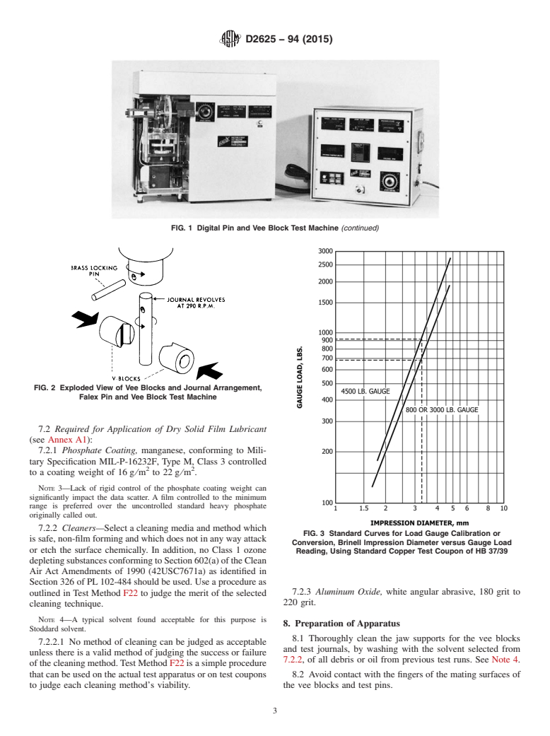
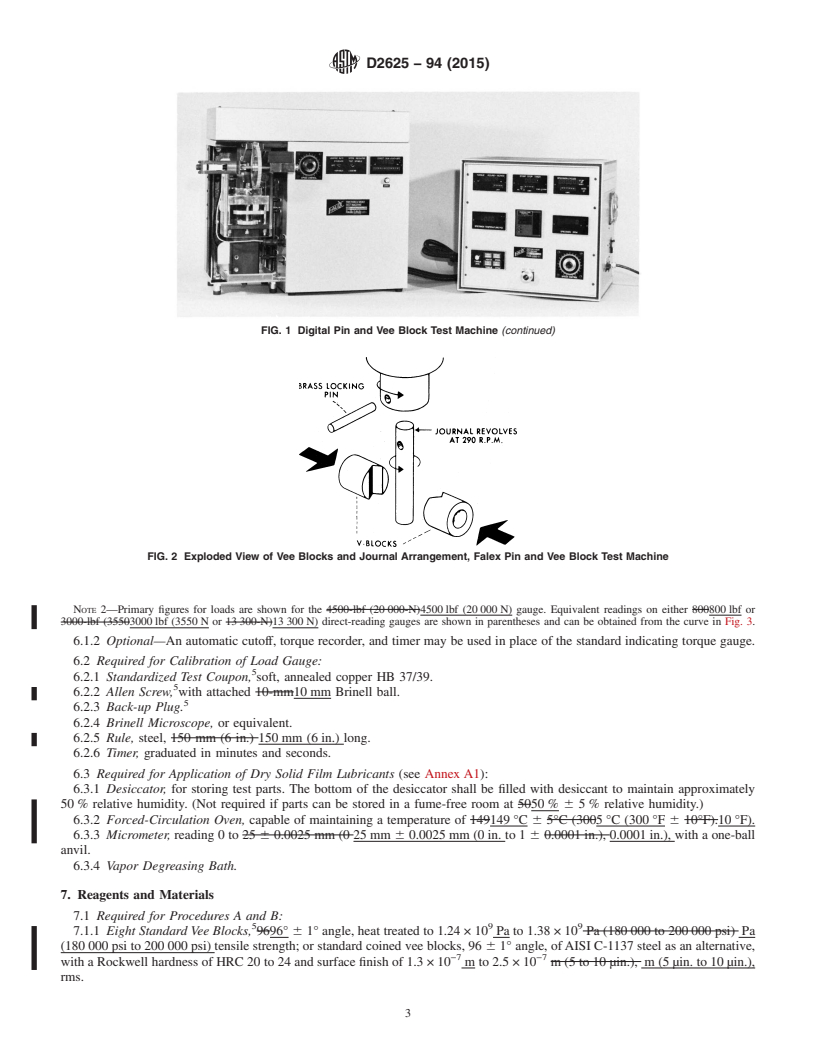
6.1 Falex Pin and Vee Block Test Machine, illustrated in Fig. 1 and Fig. 2.
6.1.1 Load Gauge, 4500-lbf (20 000-N)4500 lbf (20 000 N) range, or 3000-lbf (13 300-N)3000 lbf (13 300 N) direct-reading
gauge. An 800-lbf (3550-N)800 lbf (3550 N) direct-reading load gauge may be used for Procedure A, but does not have a high
enough load range for Procedure B.
Trademark of and available from Falex Corp., 1020 Airpark Dr., Sugar Grove, IL 60554. A new model of the Falex Pin and Vee Block Test Machine has been available
since 1983. Certain operating procedures are different for this new model. Consult instruction manual of machine for this information. If you are aware of alternative suppliers,
please provide this information to ASTM International Headquarters. Your comments will receive careful consideration at a meeting of the responsible technical committee,
which you may attend.
D2625 − 94 (2015)
FIG. 1 Digital Pin and Vee Block Test Machine (continued)
FIG. 2 Exploded View of Vee Blocks and Journal Arrangement, Falex Pin and Vee Block Test Machine
NOTE 2—Primary figures for loads are shown for the 4500-lbf (20 000-N)4500 lbf (20 000 N) gauge. Equivalent readings on either 800800 lbf or
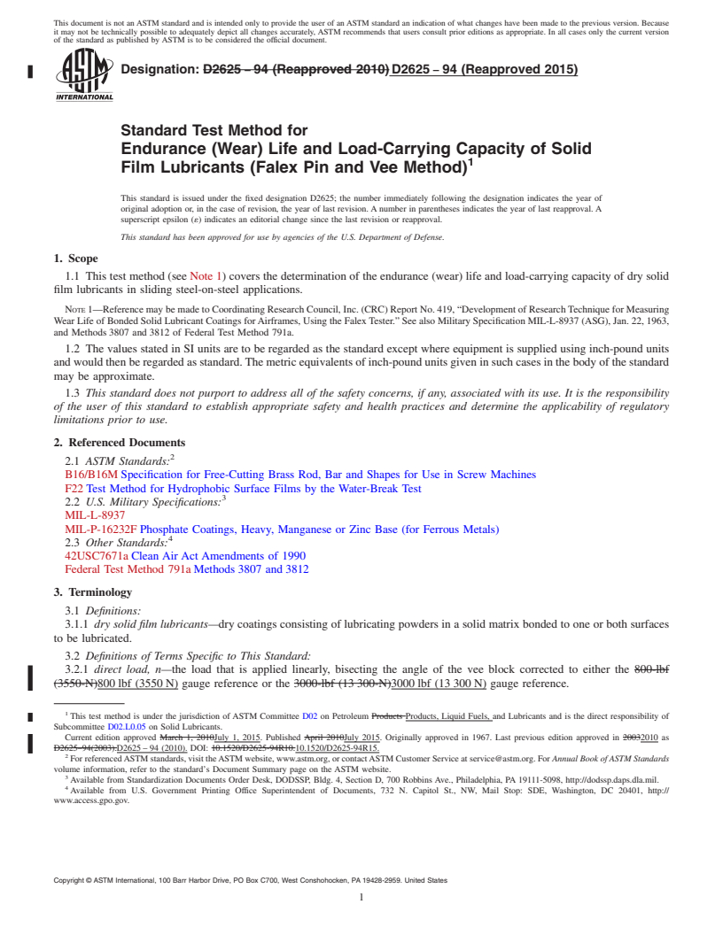
3000-lbf (35503000 lbf (3550 N or 13 300-N)13 300 N) direct-reading gauges are shown in parentheses and can be obtained from the curve in Fig. 3.
6.1.2 Optional—An automatic cutoff, torque recorder, and timer may be used in place of the standard indicating torque gauge.
6.2 Required for Calibration of Load Gauge:
6.2.1 Standardized Test Coupon, soft, annealed copper HB 37/39.
6.2.2 Allen Screw, with attached 10-mm10 mm Brinell ball.
6.2.3 Back-up Plug.
6.2.4 Brinell Microscope, or equivalent.
6.2.5 Rule, steel, 150 mm (6 in.) 150 mm (6 in.) long.
6.2.6 Timer, graduated in minutes and seconds.
6.3 Required for Application of Dry Solid Film Lubricants (see Annex A1):
6.3.1 Desiccator, for storing test parts. The bottom of the desiccator shall be filled with desiccant to maintain approximately
50 % relative humidity. (Not required if parts can be stored in a fume-free room at 5050 % 6 5 % relative humidity.)
6.3.2 Forced-Circulation Oven, capable of maintaining a temperature of 149149 °C 6 5°C (3005 °C (300 °F 6 10°F).10 °F).
6.3.3 Micrometer, reading 0 to 25 6 0.0025 mm (0 25 mm 6 0.0025 mm (0 in. to 1 6 0.0001 in.), 0.0001 in.), with a one-ball
anvil.
6.3.4 Vapor Degreasing Bath.
7. Reagents and Materials
7.1 Required for Procedures A and B:
5 9 9
7.1.1 Eight Standard Vee Blocks, 9696° 6 1° angle, heat treated to 1.24 × 10 Pa to 1.38 × 10 Pa (180 000 to 200 000 psi) Pa
(180 000 psi to 200 000 psi) tensile strength; or standard coined vee blocks, 96 6 1° angle, of AISI C-1137 steel as an alternative,
−7 −7
with a Rockwell hardness of HRC 20 to 24 and surface finish of 1.3 × 10 m to 2.5 × 10 m (5 to 10 μin.), m (5 μin. to 10 μin.),
rms.
D2625 − 94 (2015)
FIG. 3 Standard Curves for Load Gauge Calibration or Conversion, Brinell Impression Diameter versus Gauge Load Reading, Using
Standard Copper Test Coupon of HB 37/39
1 1
7.1.2 Four Standard Test Pins, 6.35-mm6.35 mm ( ⁄4-in.) in.) outside diameter by 31.75 mm 31.75 mm (1 ⁄4 in.) in.) long, heat
9 9
treated to 1.24 × 10 Pa to 1.38 × 10 Pa (180 000 to 200 000 psi) Pa (180 000 psi to 200 000 psi) ultimate hardness; or Standard
No. 8 Pins of AISI 3135 steel as an alternative, with a hardness of HRB 87 to 91, on a ground, flat surface (or approximately HRB
−7 −7
80 to 83 on the round), and a surface finish of 1.3 × 10 m to 2.5 × 10 m (5 to 10 μin.) m (5 μin. to 10 μin.) rms.
7.1.3 Locking (Shear) Pin, ⁄2 H Brass, conforming to Specification B16/B16M.
7.2 Required for Application of Dry Solid Film Lubricant (see Annex A1):
7.2.1 Phosphate Coating, manganese, conforming to Military Specification MIL-P-16232F, Type M, Class 3 controlled to a
2 2
coating weight of 1616 g ⁄m to 22 22 g g/m⁄m .
NOTE 3—Lack of rigid control of the phosphate coating weight can significantly impact the data scatter. A film controlled to the minimum range is
preferred over the uncontrolled standard heavy phosphate originally called out.
7.2.2 Cleaners—Select a cleaning media and method which is safe, non-film forming and which does not in any way attack or
etch the surface chemically. In addition, no Class 1 ozone depleting substances conforming to Section 602(a) of the Clean Air Act
Amendments of 1990 (42USC7671a) as identified in Section 326 of PL 102-484 should be used. Use a procedure as outlined in
Test Method F22 to judge the merit of the selected cleaning technique.
NOTE 4—A typical solvent found acceptable for this purpose is Stoddard solvent.
7.2.2.1 No method of cleaning can be judged as acceptable unless there is a valid method of judging the success or failure of
the cleaning method. Test Method F22 is a simple procedure that can be used on the actual test apparatus or on test coupons to
judge each cleaning method’s viability.
7.2.3 Aluminum Oxide, white angular abrasive, 180 grit to 220 grit.
8. Preparation of Apparatus
8.1 Thoroughly clean the jaw supports for the vee blocks and test journals, by washing with the solvent selected from 7.2.2,
of all debris or oil from previous test runs. See Note 4.
8.2 Avoid contact with the fingers of the mating surfaces of the vee blocks and test pins.
8.3 Avoid atmospheric contamination such as cigarette smoke, as this can adversely affect the test results.
D2625 − 94 (2015)
FIG. 4 Schematic Drawing of Calibration Accessories for Falex Pin and Vee Block Test Machine
9. Calibration of Load Gauge
9.1 Calibration Procedure with 4500-lbf (20 000-N) Load Gauge:
9.1.1 Remove the Allen set screw and 12.70-mm12.70 mm ( ⁄2-in.) in.) ball from the left jaw socket (Fig. 4).
9.1.2 Insert the special Allen screw with the attached 10-mm10 mm Brinell ball into the working face of the left jaw. Adjust
so that the ball projects about 4 mm 4 mm ( ⁄32 in.) in.) from face of the jaw.
9.1.3 Insert the back-up plug in the counterbore of the right-hand jaw. Adjust so that the plug projects about 0.8 mm 0.8 mm
( ⁄32 in.) in.) from the face.
9.1.4 Support the standard test coupon so that the upper edge of the coupon is about 2.5 mm 2.5 mm ( ⁄32 in.) in.) below the
upper surface of the jaws. Place a steel rule across the face of the jaws. Adjust the Allen screw with the attached 10-mm10 mm
ball until the face of the jaws are parallel to the steel rule with the test coupon in position for indentation.
9.1.5 With the test coupon in position for the first impression, place the load gauge assembly on the lever arms.
9.1.6 Place the loading arm on the ratchet wheel and actuate the motor. Allow the motor to run until the load gauge indicates
a load of 300 lbf (1330 N). 300 lbf (1330 N). A slight takeup on the ratchet wheel is required to hold the load due to the ball sinking
into the test coupon. After the 300-lbf (1330-N)300 lbf (1330 N) load is obtained, hold for 1 min 1 min for the indentation to form.
9.1.7 Turn off the machine and back off the load until the test coupon is free of the jaws. Advance the test coupon approximately
9.5 mm 9.5 mm ( ⁄8 in.) in.) (additional indentations should be separated by a minimum distance of 2.5 × the diameter of the initial
indentation). Check the alignment of the jaws, and repeat the procedure described in 9.1.6 at gauge loads of 750, 1000, and 1500
lbf (3300, 4450, and 6650 N).750 lbf, 1000 lbf, and 1500 lbf (3300 N, 4450 N, and 6650 N).
9.1.8 Remove the load gauge assembly and test coupon and measure the diameter of each indentation to 0.01 mm 0.01 mm with
the Brinell microscope. Make three measurements of the indentation diameter, rotating the test coupon to ensure that no two
measurements represent the same points. Average the three measurements of each impression and record.
9.1.9 Plot the four impression readings versus gauge load readings on log-log paper (K&E 467080 or equivalent). If they do
not plot as an approximately straight line, repeat steps 9.1.4 – 9.1.8. A standard curve of impression diameter versus gauge reading
is shown in Fig. 3. If the indentation diameter, plotted as above, is lower or higher than that shown on the standard curve, determine
the actual load necessary to produce the indentation diameter that will correspond to that shown on the standard curve.
NOTE 5—A full-size standard calibration curve, plotted on log-log paper and similar to Fig. 3 but with finer subdivision lines included, should be used
for accurate calibration.
9.2 Calibration Procedure with 800800 lbf or
...
Questions, Comments and Discussion
Ask us and Technical Secretary will try to provide an answer. You can facilitate discussion about the standard in here.