


ASTM B942-10(2015)
(Guide)Standard Guide for Specification and Quality Assurance for the Electrical Contact Performance of Crimped Wire Terminations
Standard Guide for Specification and Quality Assurance for the Electrical Contact Performance of Crimped Wire Terminations
SIGNIFICANCE AND USE
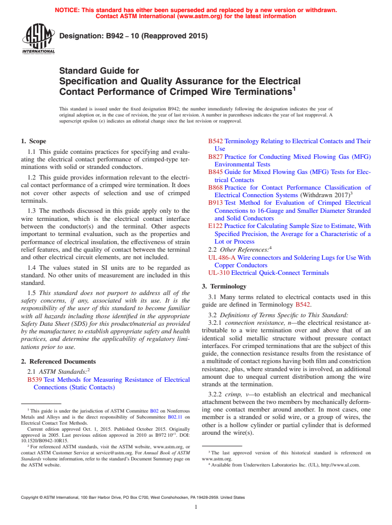
4.1 The purpose of this guide is to provide end-product manufacturers and other users with technical information and methods recommended towards the achievement of successful application of crimped wire terminals.
4.2 For any given use, there is generally a choice of terminal types available, employing different mechanical design, materials, and installation tooling. Although terminals available to choose from may be similarly rated, typically according to wire sizes and combinations, their electrical contact performance in the end product may vary substantially. For many applications, the end-product reliability and user safety is substantially influenced by the choice of terminal and the quality of the completed termination. This guidance document contains specialized information on selection, assembly, and quality control of crimped wire terminals, covering aspects considered to be necessary to achieve reliable long-term operation in the intended application. This information is not generally found in commercial literature or textbooks. The methods discussed utilize connection resistance as the primary measure of termination quality, and change of connection resistance with time as the measure of termination deterioration. The methods are based on a foundation of modern electrical contact theory and practice.
SCOPE
1.1 This guide contains practices for specifying and evaluating the electrical contact performance of crimped-type terminations with solid or stranded conductors.
1.2 This guide provides information relevant to the electrical contact performance of a crimped wire termination. It does not cover other aspects of selection and use of crimped terminals.
1.3 The methods discussed in this guide apply only to the wire termination, which is the electrical contact interface between the conductor(s) and the terminal. Other aspects important to terminal evaluation, such as the properties and performance of electrical insulation, the effectiveness of strain relief features, and the quality of contact between the terminal and other electrical circuit elements, are not included.
1.4 The values stated in SI units are to be regarded as standard. No other units of measurement are included in this standard.
1.5 This standard does not purport to address all of the safety concerns, if any, associated with its use. It is the responsibility of the user of this standard to become familiar with all hazards including those identified in the appropriate Safety Data Sheet (SDS) for this product/material as provided by the manufacturer, to establish appropriate safety and health practices, and determine the applicability of regulatory limitations prior to use.
General Information
Buy Standard
Standards Content (Sample)
NOTICE: This standard has either been superseded and replaced by a new version or withdrawn.
Contact ASTM International (www.astm.org) for the latest information
Designation:B942 −10 (Reapproved 2015)
Standard Guide for
Specification and Quality Assurance for the Electrical
Contact Performance of Crimped Wire Terminations
This standard is issued under the fixed designation B942; the number immediately following the designation indicates the year of
original adoption or, in the case of revision, the year of last revision. A number in parentheses indicates the year of last reapproval. A
superscript epsilon (´) indicates an editorial change since the last revision or reapproval.
1. Scope B542 Terminology Relating to Electrical Contacts and Their
Use
1.1 This guide contains practices for specifying and evalu-
B827 Practice for Conducting Mixed Flowing Gas (MFG)
ating the electrical contact performance of crimped-type ter-
Environmental Tests
minations with solid or stranded conductors.
B845 Guide for Mixed Flowing Gas (MFG) Tests for Elec-
1.2 This guide provides information relevant to the electri-
trical Contacts
cal contact performance of a crimped wire termination. It does
B868 Practice for Contact Performance Classification of
not cover other aspects of selection and use of crimped
Electrical Connection Systems (Withdrawn 2017)
terminals.
B913 Test Method for Evaluation of Crimped Electrical
Connections to 16-Gauge and Smaller Diameter Stranded
1.3 The methods discussed in this guide apply only to the
wire termination, which is the electrical contact interface and Solid Conductors
E122 Practice for Calculating Sample Size to Estimate,With
between the conductor(s) and the terminal. Other aspects
important to terminal evaluation, such as the properties and Specified Precision, the Average for a Characteristic of a
Lot or Process
performance of electrical insulation, the effectiveness of strain
relief features, and the quality of contact between the terminal 2.2 Other References:
and other electrical circuit elements, are not included. UL486-A WireconnectorsandSolderingLugsforUseWith
Copper Conductors
1.4 The values stated in SI units are to be regarded as
UL-310 Electrical Quick-Connect Terminals
standard. No other units of measurement are included in this
standard.
3. Terminology
1.5 This standard does not purport to address all of the
3.1 Many terms related to electrical contacts used in this
safety concerns, if any, associated with its use. It is the
guide are defined in Terminology B542.
responsibility of the user of this standard to become familiar
3.2 Definitions of Terms Specific to This Standard:
with all hazards including those identified in the appropriate
3.2.1 connection resistance, n—the electrical resistance at-
Safety Data Sheet (SDS) for this product/material as provided
tributable to a wire termination over and above that of an
by the manufacturer, to establish appropriate safety and health
identical solid metallic structure without pressure contact
practices, and determine the applicability of regulatory limi-
interfaces. For crimped terminations that are the subject of this
tations prior to use.
guide, the connection resistance results from the resistance of
amultitudeofcontactregionshavingbothfilmandconstriction
2. Referenced Documents
2 resistance, plus, where stranded wire is involved, an additional
2.1 ASTM Standards:
amount due to unequal current distribution among the wire
B539 Test Methods for Measuring Resistance of Electrical
strands at the termination.
Connections (Static Contacts)
3.2.2 crimp, v—to establish an electrical and mechanical
attachmentbetweenthetwomembersbymechanicallydeform-
ing one contact member around another. In most cases, one
This guide is under the jurisdiction of ASTM Committee B02 on Nonferrous
Metals and Alloys and is the direct responsibility of Subcommittee B02.11 on
member is a stranded or solid wire, or a group of wires, the
Electrical Contact Test Methods.
other is a hollow cylinder or partial cylinder that is deformed
Current edition approved Oct. 1, 2015. Published October 2015. Originally
ɛ1
around the wire(s).
approved in 2005. Last previous edition approved in 2010 as B972 10 . DOI:
10.1520/B0942-10R15.
For referenced ASTM standards, visit the ASTM website, www.astm.org, or
contact ASTM Customer Service at service@astm.org. For Annual Book of ASTM The last approved version of this historical standard is referenced on
Standards volume information, refer to the standard’s Document Summary page on www.astm.org.
the ASTM website. Available from Underwriters Laboratories Inc. (UL), http://www.ul.com.
Copyright © ASTM International, 100 Barr Harbor Drive, PO Box C700, West Conshohocken, PA 19428-2959. United States
B942−10 (2015)
3.2.3 crimp barrel, crimp tab, n—the portion of the crimp 5.3 In many applications, substantial connection deteriora-
terminal that is deformed in the crimping operation. tion can be tolerated because there are no harmful conse-
quences of increasing connection resistance. Crimp termina-
3.2.4 crimped termination, n—a mechanical and electrical
tion failures in other applications have potentially severe
connection between a conductor, generally a wire, and a
consequences, however, which may be avoided by use of
component, typically a terminal specifically made for the
stringent acceptance criteria and quality control methods that
purpose. The crimped termination is made by compressing
assure high quality connections.
(crimping) the component (crimp barrel) or tab(s) of the
component around the conductor using a tool specifically 5.4 A crimp termination is conceptually visualized as com-
pressed into a virtually solid mass of metal, with wire and
designed for the purpose.
terminal in intimate contact at the interfaces. Because of an
3.2.5 crimp terminal, n—a metal component designed to be
effect generally called “spring-back,” this is often incorrect.
electrically and mechanically attached to a wire by deforming
Spring-back is the elastic recovery of the distorted metal back
a portion of the component in a crimping operation to form an
towards its original shape. While the crimping dies are closed
attachment to the wire. The other end of the terminal usually
on the terminal, the surfaces are in contact. Spring-back then
has a ring, fork, spade, tab, or related configuration designed to
occurs when the crimping die is removed.
attach to another circuit element. Some crimp terminals termi-
5.5 If the outer terminal springs back more than the wire
nate multiple wires within the same crimp barrel.
strands,thenthenormalforceandtherealareaofcontactatthe
contact interfaces within the termination are substantially
4. Significance and Use
reduced. When this occurs, there may be little or no residual
4.1 The purpose of this guide is to provide end-product
compressive force at the contact interfaces within the termina-
manufacturers and other users with technical information and
tion. This degrades the mechanical integrity of the termination
methods recommended towards the achievement of successful
and also makes it more susceptible to corrosive deterioration.
application of crimped wire terminals.
Spring-back causes open spaces to develop where intimate
surface-to-surface contact is expected, allowing ingress of
4.2 Foranygivenuse,thereisgenerallyachoiceofterminal
moisture and atmospheric contaminants, thereby accelerating
types available, employing different mechanical design,
oxidation and corrosion related deterioration.
materials, and installation tooling. Although terminals avail-
abletochoosefrommaybesimilarlyrated,typicallyaccording
5.6 The selection and setup of the correct die set for the
to wire sizes and combinations, their electrical contact perfor-
particular terminal are critical factors. For a given terminal and
mance in the end product may vary substantially. For many
wire fill, there is a narrow range of compression within which
applications, the end-product reliability and user safety is
satisfactory results will be obtained. Inadequate crimping
substantially influenced by the choice of terminal and the
generally results in shortened service life. Over-crimping may
quality of the completed termination. This guidance document
also be harmful, due to crack formation in the crimp barrel,
contains specialized information on selection, assembly, and
severing of wire strands, or excessive deformation of the wire.
quality control of crimped wire terminals, covering aspects
5.7 The typical connection resistance of crimped wire ter-
considered to be necessary to achieve reliable long-term
minations when initially made will be low, about the same
operation in the intended application. This information is not
order of magnitude as the bulk resistance of the terminal. A
generally found in commercial literature or textbooks. The
newly-madeterminationof#16AWGstrandedcopperwire,for
methods discussed utilize connection resistance as the primary
example, is expected to have a connection resistance of less
measure of termination quality, and change of connection
-4
than 10 Ω (0.1 milliohm). Deterioration at the metallic
resistance with time as the measure of termination deteriora-
contact interfaces within the crimped termination may occur
tion. The methods are based on a foundation of modern
after initial installation, causing increasing connection resis-
electrical contact theory and practice.
tance with time in service. Termination deterioration may be
due to oxidation, corrosion, mechanical and/or thermal effects,
5. Connection Resistance Considerations
any of which may occur within the normal and expected
5.1 Therequiredperformanceofacrimpedwiretermination
conditions of use in a particular application.
depends on the application, and it must be determined by the
5.8 Increasing connection resistance of terminations in a
user or end-product manufacturer based on the effect that
particular end-product may influence reliability or safety, or
connection resistance may have on the reliability or safety, or
both, depending on the particular function and current for each
both, of the end product. To satisfy the more demanding
crimped termination in the circuit. Within a given product,
application requirements, it is necessary to establish adequate
there may be crimp terminations having substantially different
initial metallic contact at the wire-to-connector interface and
reliability and safety requirements.
maintain that contact over many decades of service without
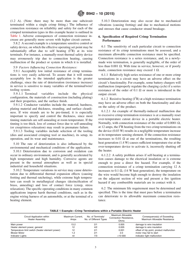
5.8.1 Anexampleisaportableheaterintendedforretailsale
maintenance or inspections.
and residential use. There are eight crimped wire terminations
5.2 A crimped wire termination is intended to be a perma- in the unit’s internal wiring that are in series with the heating
nent electrical contact. Current passes through a multitude of element, which draws 12A.There are also seven crimped wire
contactinterfacesamongthewirestrandsandfromsomeofthe terminations associated with neon indicator lights (less than
strands to the connector body. 0.01 A), and another four in the heater’s blower motor circuit
B942−10 (2015)
(1.2 A). (Note: there may be more than one subcircuit 5.10.3 Deterioration may also occur due to mechanical
terminated within a single crimp fitting.) The influence of vibrations (causing fretting) and due to mechanical motions
connection resistance on reliability and safety for each of the
and stresses that cause conductor strand breakage.
crimped termination types in this example heater is outlined in
Table 1. Adverse consequences of connection resistance in-
6. Specification of Required Crimp Termination
crease are generally more severe with higher circuit current.
Performance
5.8.2 Asecondexampleisatemperaturesensitivecontrolor
6.1 The sensitivity of each particular circuit to connection
safetydevice,onwhichtheeffectiveoperatingsetpointmaybe
resistance of its crimp terminations must be assessed, and a
substantially offset due to self heating (I R) at its wire
maximum allowable connection resistance must be specified.
terminals. For instance, a manually-reset thermal safety device
may erroneously trip due to connection heating, causing Connection resistance is a series resistance, and, in a newly-
malfunction of the product or system in which it is installed. made wire termination, is generally negligible, of the order of
less than 0.001 Ω. With time in service, however, or if poorly
5.9 Factors Influencing Connection Resistance:
made, connection resistance may exceed 1 Ω.
5.9.1 Acceptably low initial resistance of crimp termina-
tions is very easily achieved. To assure that it will remain 6.1.1 Relatively high series resistance of one or more crimp
acceptably low in the intended application is the greater
terminations in a circuit may have an adverse effect on the
challenge, since the rate of deterioration (resistance increase)
circuit’s functionality. For example, some battery chargers will
in service is sensitive to many variables of the terminal/wire/
malfunction(improperlyregulatethechargingcycle)ifaseries
tooling system.
resistance of the order of 0.1 Ω or more is introduced in the
5.9.1.1 Terminal variables include the physical
output circuit.
configuration, the materials of construction (including plating) 2
6.1.2 Resistiveheating(I R)atahighresistancetermination
and their properties, and the surface finish.
may have an adverse effect on both the functionality and also
5.9.1.2 Conductor variables include the material, hardness,
on the safety of the product.
plating material and thickness, stranding, and surface cleanli-
6.1.2.1 An example of thermally-induced malfunction due
ness. If wire strands are to be pre-tinned, it is especially
to excessive crimp termination resistance is at a manually reset
important to specify and control the thickness, since most
over-temperature cutout device in a portable electric heater.
tinning materials are self-annealing at room temperature. If the
Normally, with connection resistance of the order of 0.0001Ω,
tinning is too thick, loss of contact force due to self-annealing
at12amps,theI Rheatingfromthetwocrimpterminationson
(or creep/stress relaxation) may result in premature failure.
thedevice(0.03W)resultsinanegligibletemperatureincrease
5.9.1.3 Tooling variables include selection of the tooling
at its temperature sensing element. If the connection resistance
(dies and associated crimping tool or machine), its setup, its
operation, and its wear and maintenance. increases to 0.01 Ω at one of the terminations, the resulting
heatgeneration(1.4W)causessufficienttemperatureriseatthe
5.10 The rate of deterioration is also influenced by the
over-temperature device to activate it, incorrectly shutting off
environmental and mechanical conditions of the application.
the heater.
5.10.1 Deterioration due to corrosion and oxidation ca
...
This document is not an ASTM standard and is intended only to provide the user of an ASTM standard an indication of what changes have been made to the previous version. Because
it may not be technically possible to adequately depict all changes accurately, ASTM recommends that users consult prior editions as appropriate. In all cases only the current version
of the standard as published by ASTM is to be considered the official document.
´1
Designation: B942 − 10 B942 − 10 (Reapproved 2015)
Standard Guide for
Specification and Quality Assurance for the Electrical
Contact Performance of Crimped Wire Terminations
This standard is issued under the fixed designation B942; the number immediately following the designation indicates the year of
original adoption or, in the case of revision, the year of last revision. A number in parentheses indicates the year of last reapproval. A
superscript epsilon (´) indicates an editorial change since the last revision or reapproval.
ε NOTE—A Summary of Changes was added editorially in January 2011.
1. Scope*Scope
1.1 This guide contains practices for specifying and evaluating the electrical contact performance of crimped-type terminations
with solid or stranded conductors.
1.2 This guide provides information relevant to the electrical contact performance of a crimped wire termination. It does not
cover other aspects of selection and use of crimped terminals.
1.3 The methods discussed in this guide apply only to the wire termination, which is the electrical contact interface between
the conductor(s) and the terminal. Other aspects important to terminal evaluation, such as the properties and performance of
electrical insulation, the effectiveness of strain relief features, and the quality of contact between the terminal and other electrical
circuit elements, are not included.
1.4 The values stated in SI units are to be regarded as standard. No other units of measurement are included in this standard.
1.5 This standard does not purport to address all of the safety concerns, if any, associated with its use. It is the responsibility
of the user of this standard to become familiar with all hazards including those identified in the appropriate Material Safety Data
Sheet (MSDS)(SDS) for this product/material as provided by the manufacturer, to establish appropriate safety and health practices,
and determine the applicability of regulatory limitations prior to use.
2. Referenced Documents
2.1 ASTM Standards:
B539 Test Methods for Measuring Resistance of Electrical Connections (Static Contacts)
B542 Terminology Relating to Electrical Contacts and Their Use
B827 Practice for Conducting Mixed Flowing Gas (MFG) Environmental Tests
B845 Guide for Mixed Flowing Gas (MFG) Tests for Electrical Contacts
B868 Practice for Contact Performance Classification of Electrical Connection Systems
B913 Test Method for Evaluation of Crimped Electrical Connections to 16-Gauge and Smaller Diameter Stranded and Solid
Conductors
E122 Practice for Calculating Sample Size to Estimate, With Specified Precision, the Average for a Characteristic of a Lot or
Process
2.2 Other References:
UL 486-A Wire connectors and Soldering Lugs for Use With Copper Conductors
UL-310 Electrical Quick-Connect Terminals
3. Terminology
3.1 Many terms related to electrical contacts used in this guide are defined in Terminology B542.
3.2 Definitions of Terms Specific to This Standard:
This guide is under the jurisdiction of ASTM Committee B02 on Nonferrous Metals and Alloys and is the direct responsibility of Subcommittee B02.11 on Electrical
Contact Test Methods.
Current edition approved Oct. 1, 2010Oct. 1, 2015. Published October 2010October 2015. Originally approved in 2005. Last previous edition approved in 20052010 as
ɛ1
B972 - 05.B972 10 . DOI: 10.1520/B0942-10E01.10.1520/B0942-10R15.
For referenced ASTM standards, visit the ASTM website, www.astm.org, or contact ASTM Customer Service at service@astm.org. For Annual Book of ASTM Standards
volume information, refer to the standard’sstandard’s Document Summary page on the ASTM website.
Available from Underwriters Laboratories Inc. (UL), http://www.ul.com.
*A Summary of Changes section appears at the end of this standard
Copyright © ASTM International, 100 Barr Harbor Drive, PO Box C700, West Conshohocken, PA 19428-2959. United States
B942 − 10 (2015)
3.2.1 connection resistance, n—the electrical resistance attributable to a wire termination over and above that of an identical
solid metallic structure without pressure contact interfaces. For crimped terminations that are the subject of this guide, the
connection resistance results from the resistance of a multitude of contact regions having both film and constriction resistance, plus,
where stranded wire is involved, an additional amount due to unequal current distribution among the wire strands at the
termination.
3.2.2 crimp, v—to establish an electrical and mechanical attachment between the two members by mechanically deforming one
contact member around another. In most cases, one member is a stranded or solid wire, or a group of wires, the other is a hollow
cylinder or partial cylinder that is deformed around the wire(s).
3.2.3 crimp barrel, crimp tab, n—the portion of the crimp terminal that is deformed in the crimping operation.
3.2.4 crimped termination, n—a mechanical and electrical connection between a conductor, generally a wire, and a component,
typically a terminal specifically made for the purpose. The crimped termination is made by compressing (crimping) the component
(crimp barrel) or tab(s) of the component around the conductor using a tool specifically designed for the purpose.
3.2.5 crimp terminal, n—a metal component designed to be electrically and mechanically attached to a wire by deforming a
portion of the component in a crimping operation to form an attachment to the wire. The other end of the terminal usually has a
ring, fork, spade, tab, or related configuration designed to attach to another circuit element. Some crimp terminals terminate
multiple wires within the same crimp barrel.
4. Significance and Use
4.1 The purpose of this guide is to provide end-product manufacturers and other users with technical information and methods
recommended towards the achievement of successful application of crimped wire terminals.
4.2 For any given use, there is generally a choice of terminal types available, employing different mechanical design, materials,
and installation tooling. Although terminals available to choose from may be similarly rated, typically according to wire sizes and
combinations, their electrical contact performance in the end product may vary substantially. For many applications, the
end-product reliability and user safety is substantially influenced by the choice of terminal and the quality of the completed
termination. This guidance document contains specialized information on selection, assembly, and quality control of crimped wire
terminals, covering aspects considered to be necessary to achieve reliable long-term operation in the intended application. This
information is not generally found in commercial literature or textbooks. The methods discussed utilize connection resistance as
the primary measure of termination quality, and change of connection resistance with time as the measure of termination
deterioration. The methods are based on a foundation of modern electrical contact theory and practice.
5. Connection Resistance Considerations
5.1 The required performance of a crimped wire termination depends on the application, and it must be determined by the user
or end-product manufacturer based on the effect that connection resistance may have on the reliability or safety, or both, of the
end product. To satisfy the more demanding application requirements, it is necessary to establish adequate initial metallic contact
at the wire-to-connector interface and maintain that contact over many decades of service without maintenance or inspections.
5.2 A crimped wire termination is intended to be a permanent electrical contact. Current passes through a multitude of contact
interfaces among the wire strands and from some of the strands to the connector body.
5.3 In many applications, substantial connection deterioration can be tolerated because there are no harmful consequences of
increasing connection resistance. Crimp termination failures in other applications have potentially severe consequences, however,
which may be avoided by use of stringent acceptance criteria and quality control methods that assure high quality connections.
5.4 A crimp termination is conceptually visualized as compressed into a virtually solid mass of metal, with wire and terminal
in intimate contact at the interfaces. Because of an effect generally called “spring-back,” this is often incorrect. Spring-back is the
elastic recovery of the distorted metal back towards its original shape. While the crimping dies are closed on the terminal, the
surfaces are in contact. Spring-back then occurs when the crimping die is removed.
5.5 If the outer terminal springs back more than the wire strands, then the normal force and the real area of contact at the contact
interfaces within the termination are substantially reduced. When this occurs, there may be little or no residual compressive force
at the contact interfaces within the termination. This degrades the mechanical integrity of the termination and also makes it more
susceptible to corrosive deterioration. Spring-back causes open spaces to develop where intimate surface-to-surface contact is
expected, allowing ingress of moisture and atmospheric contaminants, thereby accelerating oxidation and corrosion related
deterioration.
5.6 The selection and setup of the correct die set for the particular terminal are critical factors. For a given terminal and wire
fill, there is a narrow range of compression within which satisfactory results will be obtained. Inadequate crimping generally results
in shortened service life. Over-crimping may also be harmful, due to crack formation in the crimp barrel, severing of wire strands,
or excessive deformation of the wire.
B942 − 10 (2015)
5.7 The typical connection resistance of crimped wire terminations when initially made will be low, about the same order of
magnitude as the bulk resistance of the terminal. A newly-made termination of #16 AWG stranded copper wire, for example, is
-4
expected to have a connection resistance of less than 10 ΩΩ (0.1 milliohm). Deterioration at the metallic contact interfaces within
the crimped termination may occur after initial installation, causing increasing connection resistance with time in service.
Termination deterioration may be due to oxidation, corrosion, mechanical and/or thermal effects, any of which may occur within
the normal and expected conditions of use in a particular application.
5.8 Increasing connection resistance of terminations in a particular end-product may influence reliability or safety, or both,
depending on the particular function and current for each crimped termination in the circuit. Within a given product, there may
be crimp terminations having substantially different reliability and safety requirements.
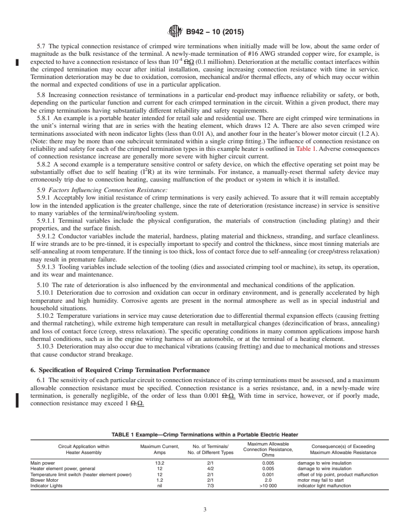
5.8.1 An example is a portable heater intended for retail sale and residential use. There are eight crimped wire terminations in
the unit’s internal wiring that are in series with the heating element, which draws 12 A. There are also seven crimped wire
terminations associated with neon indicator lights (less than 0.01 A), and another four in the heater’s blower motor circuit (1.2 A).
(Note: there may be more than one subcircuit terminated within a single crimp fitting.) The influence of connection resistance on
reliability and safety for each of the crimped termination types in this example heater is outlined in Table 1. Adverse consequences
of connection resistance increase are generally more severe with higher circuit current.
5.8.2 A second example is a temperature sensitive control or safety device, on which the effective operating set point may be
substantially offset due to self heating (I R) at its wire terminals. For instance, a manually-reset thermal safety device may
erroneously trip due to connection heating, causing malfunction of the product or system in which it is installed.
5.9 Factors Influencing Connection Resistance:
5.9.1 Acceptably low initial resistance of crimp terminations is very easily achieved. To assure that it will remain acceptably
low in the intended application is the greater challenge, since the rate of deterioration (resistance increase) in service is sensitive
to many variables of the terminal/wire/tooling system.
5.9.1.1 Terminal variables include the physical configuration, the materials of construction (including plating) and their
properties, and the surface finish.
5.9.1.2 Conductor variables include the material, hardness, plating material and thickness, stranding, and surface cleanliness.
If wire strands are to be pre-tinned, it is especially important to specify and control the thickness, since most tinning materials are
self-annealing at room temperature. If the tinning is too thick, loss of contact force due to self-annealing (or creep/stress relaxation)
may result in premature failure.
5.9.1.3 Tooling variables include selection of the tooling (dies and associated crimping tool or machine), its setup, its operation,
and its wear and maintenance.
5.10 The rate of deterioration is also influenced by the environmental and mechanical conditions of the application.
5.10.1 Deterioration due to corrosion and oxidation can occur in ordinary environment, and is generally accelerated by high
temperature and high humidity. Corrosive agents are present in the normal atmosphere as well as in special industrial and
household situations.
5.10.2 Temperature variations in service may cause deterioration due to differential thermal expansion effects (causing fretting
and thermal ratcheting), while extreme high temperature can result in metallurgical changes (dezincification of brass, annealing)
and loss of contact force (creep, stress relaxation). The specific operating conditions in many common applications impose harsh
thermal conditions, such as in the engine wiring harness of an automobile, or at the terminal of a heating element.
5.10.3 Deterioration may also occur due to mechanical vibrations (causing fretting) and due to mechanical motions and stresses
that cause conductor strand breakage.
6. Specification of Required Crimp Termination Performance
6.1 The sensitivity of each particular circuit to connection resistance of its crimp terminations must be assessed, and a maximum
allowable connection resistance must be specified. Connection resistance is a series resistance, and, in a newly-made wire
termination, is generally negligible, of the order
...
Questions, Comments and Discussion
Ask us and Technical Secretary will try to provide an answer. You can facilitate discussion about the standard in here.