


ASTM F2321-14(2020)
(Specification)Standard Specification for Flexible and Rigid Insulated Temporary By-Pass Jumpers
Standard Specification for Flexible and Rigid Insulated Temporary By-Pass Jumpers
ABSTRACT
These specifications provides the manufacture and testing, as well as individual design, electrical, mechanical, and workmanship requirements for a system of flexible insulated temporary bypass jumpers used on energized power lines and equipment. These specifications for a system of bypass jumpers are covered in four parts as follows: clamps for bypass jumpers; ferrules for bypass jumpers; cable for bypass jumpers; and bypass jumpers (complete assembly with clamps, ferrules, and cable). The use and maintenance of these equipments are not addressed in these specifications.
SCOPE
1.1 These specifications cover the manufacture and testing of flexible insulated temporary By-Pass jumpers (By-Pass jumpers) used on energized power lines and equipment.
1.2 It is common practice for the user of this protective equipment to prepare complete instructions and safety regulations to govern in detail the correct and safe use of such equipment. Also see 4.2.
1.3 The use and maintenance of this equipment are beyond the scope of these specifications.
1.4 These specifications for a system of By-Pass jumpers is covered in four parts as follows:
Title
Sections
Clamps for By-Pass Jumpers
5 – 17
Ferrules for By-Pass Jumpers
18 – 31
Cable for By-Pass Jumpers
32 – 40
By-Pass Jumpers (complete assembly
with clamps, ferrules, and cable)
41 – 55
1.5 Each of the four parts is an entity of itself, but is listed as a part of the system for completeness and clarification.
1.6 The values stated in SI units are to be regarded as the standard. See IEEE/ASTM SI 10.
1.7 The following precautionary caveat pertains only to the test method portions, Sections 13, 26, 48, and 55 of this specification. This standard does not purport to address all of the safety concerns, if any, associated with its use. It is the responsibility of the user of this standard to establish appropriate safety, health, and environmental practices and determine the applicability of regulatory limitations prior to use.
1.8 This international standard was developed in accordance with internationally recognized principles on standardization established in the Decision on Principles for the Development of International Standards, Guides and Recommendations issued by the World Trade Organization Technical Barriers to Trade (TBT) Committee.
General Information
Buy Standard
Standards Content (Sample)
NOTICE: This standard has either been superseded and replaced by a new version or withdrawn.
Contact ASTM International (www.astm.org) for the latest information
Designation: F2321 − 14 (Reapproved 2020)
Standard Specification for
Flexible and Rigid Insulated Temporary By-Pass Jumpers
This standard is issued under the fixed designation F2321; the number immediately following the designation indicates the year of
original adoption or, in the case of revision, the year of last revision. A number in parentheses indicates the year of last reapproval. A
superscript epsilon (´) indicates an editorial change since the last revision or reapproval.
1. Scope mendations issued by the World Trade Organization Technical
Barriers to Trade (TBT) Committee.
1.1 These specifications cover the manufacture and testing
of flexible insulated temporary By-Pass jumpers (By-Pass
2. Referenced Documents
jumpers) used on energized power lines and equipment.
2.1 ASTM Standards:
1.2 It is common practice for the user of this protective
B33 Specification for Tin-Coated Soft or Annealed Copper
equipment to prepare complete instructions and safety regula-
Wire for Electrical Purposes
tions to govern in detail the correct and safe use of such
B172 Specification for Rope-Lay-Stranded Copper Conduc-
equipment. Also see 4.2.
tors Having Bunch-Stranded Members, for Electrical Con-
ductors
1.3 The use and maintenance of this equipment are beyond
B173 Specification for Rope-Lay-Stranded Copper Conduc-
the scope of these specifications.
tors Having Concentric-Stranded Members, for Electrical
1.4 These specifications for a system of By-Pass jumpers is
Conductors
covered in four parts as follows:
D2768 Specification for General-Purpose Ethylene-
Title Sections
Propylene Rubber Jacket for Wire and Cable (Withdrawn
Clamps for By-Pass Jumpers 5 – 17
2007)
Ferrules for By-Pass Jumpers 18 – 31
Cable for By-Pass Jumpers 32 – 40
D2770 Specification for Ozone-Resisting Ethylene-
By-Pass Jumpers (complete assembly 41 – 55
Propylene Rubber Integral Insulation and Jacket for Wire
with clamps, ferrules, and cable)
and Cable (Withdrawn 2007)
1.5 Each of the four parts is an entity of itself, but is listed
D2802 Specification for Ozone-Resistant Ethylene-Alkene
as a part of the system for completeness and clarification.
Polymer Insulation for Wire and Cable
1.6 The values stated in SI units are to be regarded as the D2865 Practice for Calibration of Standards and Equipment
standard. See IEEE/ASTM SI 10.
for Electrical Insulating Materials Testing
E8 Test Methods for Tension Testing of Metallic Materials
1.7 The following precautionary caveat pertains only to the
[Metric] E0008_E0008M
test method portions, Sections 13, 26, 48, and 55 of this
F819 Terminology Relating to Electrical Protective Equip-
specification. This standard does not purport to address all of
ment for Workers
the safety concerns, if any, associated with its use. It is the
IEEE/ASTM SI 10 American National Standard for Metric
responsibility of the user of this standard to establish appro-
Practice
priate safety, health, and environmental practices and deter-
2.2 ANSI Standards:
mine the applicability of regulatory limitations prior to use.
ANSI C39.5 Safety Requirements for Electrical and Elec-
1.8 This international standard was developed in accor-
tronic Measuring and Controlling Instruments
dance with internationally recognized principles on standard-
ANSI C84.1 Voltage Ratings for Electric Power Systems and
ization established in the Decision on Principles for the
Equipment (60 Hz)
Development of International Standards, Guides and Recom-
For referenced ASTM standards, visit the ASTM website, www.astm.org, or
contact ASTM Customer Service at service@astm.org. For Annual Book of ASTM
This specification is under the jurisdiction of ASTM Committee F18 on Standards volume information, refer to the standard’s Document Summary page on
Electrical Protective Equipment for Workers and is the direct responsibility of the ASTM website.
Subcommittee F18.45 on Mechanical Apparatus. The last approved version of this historical standard is referenced on www.ast-
Current edition approved Feb. 15, 2020. Published March 2020. Originally m.org.
approved in 2003. Last previous edition approved in 2014 as F2321–14. DOI: Available from American National Standards Institute (ANSI), 25 W. 43rd St.,
10.1520/F2321-14R20. 4th Floor, New York, NY 10036.
Copyright © ASTM International, 100 Barr Harbor Drive, PO Box C700, West Conshohocken, PA 19428-2959. United States
F2321 − 14 (2020)
ANSI C119.4 American National Standard for Electrical for short periods of time at work locations when conductors or
Connectors equipment may otherwise be opened or made discontinuous
2.3 NEMA Standard: during work operations. By-Pass jumpers are insulated to
temporarily protect personnel from brush or accidental contact
WC 8 Ethylene-Propylene-Rubber Insulated Wire and Cable
for the Transmission and Distribution of Electrical Energy only; therefore, when authorizing their use, a margin of safety
should be provided between the maximum voltage used on,
(formerly ICEA S-68-516)
and the proof-test voltage at which they are tested. The
3. Terminology
relationship between proof-test voltage and the maximum
voltage at which By-Pass jumpers are used is shown in Table
3.1 Definitions:
1. Warning—Portions of these devices (clamps and ferrules)
3.1.1 flexible and rigid insulated temporary By-Pass
are not insulated and offer no protection from accidental
jumpers—devices designed and used to keep electric supply
contact.
circuits effectively continuous (electrically bridged) for short
periods of time at work locations when conductors or equip-
CLAMPS FOR BY-PASS JUMPERS
ment may otherwise be opened or made electrically discon-
tinuous during work operations.
5. Scope
3.1.1.1 Discussion—The devices are normally installed,
5.1 This specification covers clamps used in the assembly of
used, and removed as part of a protective insulating system
By-Pass jumpers.
composed of insulating covers and/or observances of required
minimum safe approach distances for workers.
6. Classification
3.1.2 voltage, normal design—a nominal value consistent
6.1 Clamps are furnished in, but not limited to, two styles
with the latest revision of ANSI C84.1, assigned to the circuit
according to their function and method of installation.
or system for the purpose of conveniently designating its
6.1.1 Style I—Clamps equipped with insulated handles for
voltage class.
installation on energized conductors with rubber gloves. See
3.1.3 voltage, maximum use—the ac voltage (rms) classifi-
Fig. 1.
cation of the protective equipment that designates the maxi-
6.1.1.1 Insulated handles may be either clear or opaque.
mum nominal design voltage of the energized system that may
6.1.1.2 Insulating materials used in this specification in-
be safely worked. The nominal design voltage is equal to
clude thermo-set plastic, elastomers, elastomer compounds,
phase-to-phase voltage on multiphase circuits.
thermoplastic polymers or any combination, regardless of
3.1.3.1 Discussion—If there is no multiphase exposure in a
origin.
system area, and the voltage exposure is limited to phase
6.1.2 Style II—Clamps equipped with provisions for instal-
(polarity on dc systems) to ground potential, the phase (polarity
lation on energized conductors with live line tools. See Fig. 2
on dc systems) to ground potential shall be considered to be the
and Fig. 3.
nominal design voltage.
6.1.2.1 Clamps are furnished according to mechanical
3.1.3.2 Discussion—If electrical equipment and devices are
strength and current rating. See Table 2.
insulated or isolated, or both, such that the multiphase exposure
6.2 Clamps are furnished in two classes according to the
on a grounded wye circuit is removed, then the nominal design
characteristics of the main contact jaws.
voltage may be considered as the phase-to-ground voltage on
6.2.1 Class A—Clamp jaws with smooth contact surfaces.
that circuit.
6.2.2 Class B—Clamp jaws with serrations, crosshatching
NOTE 1—The work practices and methods associated with removing
or other means intended to abrade or bite through corrosion
multiphase exposures at any given work site are not addressed in this
products on the surface of the conductor being clamped.
specification.
3.2 For definitions of other terms, refer to Terminology
7. Sizes
F819.
7.1 Clamp size is the combination of the main contact and
cable size ranges as listed by the manufacturers.
4. Significance and Use
4.1 These specifications cover the minimum electrical and
8. Ordering Information
physical properties designated by the manufacturer and the
8.1 Orders for clamps under this specification shall include
detailed procedures by which such properties are to be deter-
this ASTM designation and the following information:
mined. The purchaser may at his option perform or have
performed any of these tests in order to verify the manufactur-
er’s designation. Claims for failure to meet the specification are
TABLE 1 Proof Test/Use Voltage Relationship
subject to verification by the manufacturer.
Maximum AC Proof DC Proof
Voltage
Use Voltage Test Voltage Test Voltage
Rating
4.2 By-Pass jumpers are devices designed and used to keep
(rms) V (rms) V (avg) V
electrical circuits effectively continuous (electrically bridged)
15 kV 15 000 20 000 50 000
25 kV 25 000 30 000 60 000
35 kV 35 000 40 000 70 000
Available from National Electrical Manufacturers Association (NEMA), 1300 69 kV 69 000 74 000
N. 17th St., Suite 1847, Rosslyn, VA 22209.
F2321 − 14 (2020)
FIG. 3 Style II Duck Bill Shape Clamp
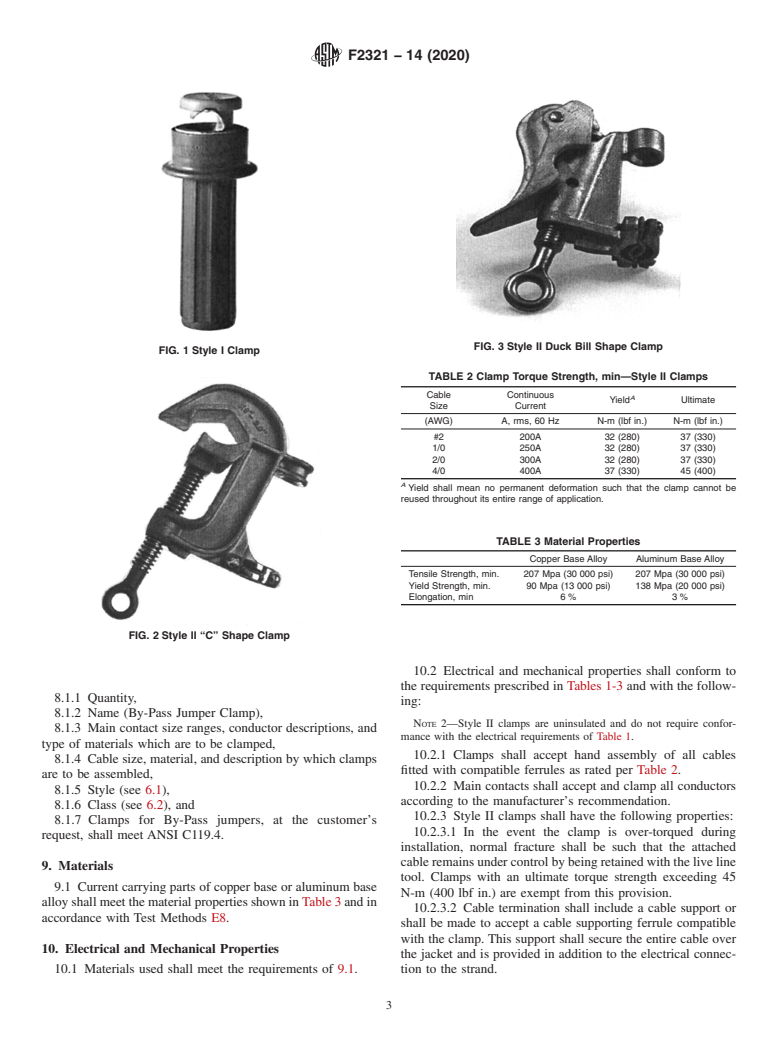
FIG. 1 Style I Clamp
TABLE 2 Clamp Torque Strength, min—Style II Clamps
Cable Continuous
A
Yield Ultimate
Size Current
(AWG) A, rms, 60 Hz N-m (lbf in.) N-m (lbf in.)
#2 200A 32 (280) 37 (330)
1/0 250A 32 (280) 37 (330)
2/0 300A 32 (280) 37 (330)
4/0 400A 37 (330) 45 (400)
A
Yield shall mean no permanent deformation such that the clamp cannot be
reused throughout its entire range of application.
TABLE 3 Material Properties
Copper Base Alloy Aluminum Base Alloy
Tensile Strength, min. 207 Mpa (30 000 psi) 207 Mpa (30 000 psi)
Yield Strength, min. 90 Mpa (13 000 psi) 138 Mpa (20 000 psi)
Elongation, min 6 % 3 %
FIG. 2 Style II “C” Shape Clamp
10.2 Electrical and mechanical properties shall conform to
the requirements prescribed in Tables 1-3 and with the follow-
8.1.1 Quantity,
ing:
8.1.2 Name (By-Pass Jumper Clamp),
NOTE 2—Style II clamps are uninsulated and do not require confor-
8.1.3 Main contact size ranges, conductor descriptions, and
mance with the electrical requirements of Table 1.
type of materials which are to be clamped,
10.2.1 Clamps shall accept hand assembly of all cables
8.1.4 Cable size, material, and description by which clamps
fitted with compatible ferrules as rated per Table 2.
are to be assembled,
10.2.2 Main contacts shall accept and clamp all conductors
8.1.5 Style (see 6.1),
according to the manufacturer’s recommendation.
8.1.6 Class (see 6.2), and
10.2.3 Style II clamps shall have the following properties:
8.1.7 Clamps for By-Pass jumpers, at the customer’s
10.2.3.1 In the event the clamp is over-torqued during
request, shall meet ANSI C119.4.
installation, normal fracture shall be such that the attached
cable remains under control by being retained with the live line
9. Materials
tool. Clamps with an ultimate torque strength exceeding 45
9.1 Current carrying parts of copper base or aluminum base
N-m (400 lbf in.) are exempt from this provision.
alloy shall meet the material properties shown in Table 3 and in
10.2.3.2 Cable termination shall include a cable support or
accordance with Test Methods E8.
shall be made to accept a cable supporting ferrule compatible
with the clamp. This support shall secure the entire cable over
10. Electrical and Mechanical Properties
the jacket and is provided in addition to the electrical connec-
10.1 Materials used shall meet the requirements of 9.1. tion to the strand.
F2321 − 14 (2020)
10.2.3.3 Clamps shall be compatible with clamp sticks and 13.3 Continuous Current Rating:
shall fit securely inside the 13 mm ( ⁄2-in.) wide slot in the head 13.3.1 Test the clamp at the continuous current level for
of the stick. which it is rated. The temperature shall be measured at the
10.2.4 Main contacts shall accept and clamp all conductors warmest spot on clamp and on the metal strand at the midpoint
or structural members in accordance with the manufacturer’s of an attached cable, which is a minimum of 1.5 m (5 ft.) in
rating. length. The maximum temperature of the clamp shall be lower
than the midpoint temperature of the maximum size copper
11. Workmanship, Finish, and Appearance
main or tap cable for which the clamp is rated.
11.1 Components shall be free of structural porosity, fins,
14. Inspection and Product Testing
sharp edges, splits, cracks and other defects that affect handling
14.1 The clamps shall be inspected and tested as follows:
or performance.
14.1.1 Verification of the main contact and cable capacities
11.2 All parts shall be formed, machined, and assembled
are in accordance with 10.2.2 and 10.2.3.
with sufficient accuracy for smooth operation by hand, and
14.1.2 Visual inspection and hand operation shall be done to
shall be free of excessive looseness to the extent detrimental to
verify workmanship, finish, and appearance, which shall be in
repeated applications at the recommended installing torque.
accordance with Section 11.
11.3 Class A (smooth jaw) clamps shall have smooth contact 14.1.3 Torque test on a test sample shall be in accordance
surfaces free of burrs, fins, or other protuberances that would with 13.2.
impair performance.
15. Acceptance, Rejection and Rehearing
11.4 Class B (serrated jaw) clamps shall have longitudinally
15.1 At the option of the purchaser, a production lot may be
level surface, that, with clamp movement as specified by the
subjected to the following:
manufacturer, will provide a cleaning effect on the surface of
15.1.1 Inspection in accordance with 14.1 for operation,
the conductor.
main contact range, workmanship, and appearance. Individual
11.5 Slag grinding marks, depressions, and other surface
clamps that do not conform may be rejected.
irregularities that do not affect strength, performance, or
15.2 Material that fails to conform to the requirements of
handling are not cause for rejection.
this specification may be rejected. Rejection should be reported
to the producer or supplier promptly and in writing. In case of
12. Sampling
dissatisfaction with the results of the test, the producer or
12.1 A product model represents a manufacturer’s design
supplier may make claim for a rehearing.
specification standard according to which the production lot is
15.3 I
...
This document is not an ASTM standard and is intended only to provide the user of an ASTM standard an indication of what changes have been made to the previous version. Because
it may not be technically possible to adequately depict all changes accurately, ASTM recommends that users consult prior editions as appropriate. In all cases only the current version
of the standard as published by ASTM is to be considered the official document.
Designation: F2321 − 14 F2321 − 14 (Reapproved 2020)
Standard Specification for
Flexible and Rigid Insulated Temporary By-Pass Jumpers
This standard is issued under the fixed designation F2321; the number immediately following the designation indicates the year of
original adoption or, in the case of revision, the year of last revision. A number in parentheses indicates the year of last reapproval. A
superscript epsilon (´) indicates an editorial change since the last revision or reapproval.
1. Scope
1.1 These specifications cover the manufacture and testing of flexible insulated temporary By-Pass jumpers (By-Pass jumpers)
used on energized power lines and equipment.
1.2 It is common practice for the user of this protective equipment to prepare complete instructions and safety regulations to
govern in detail the correct and safe use of such equipment. Also see 4.2.
1.3 The use and maintenance of this equipment are beyond the scope of these specifications.
1.4 These specifications for a system of By-Pass jumpers is covered in four parts as follows:
Title Sections
Clamps for By-Pass Jumpers 5 – 17
Ferrules for By-Pass Jumpers 18 – 31
Cable for By-Pass Jumpers 32 – 40
By-Pass Jumpers (complete assembly 41 – 55
with clamps, ferrules, and cable)
1.5 Each of the four parts is an entity of itself, but is listed as a part of the system for completeness and clarification.
1.6 The values stated in SI units are to be regarded as the standard. See IEEE/ASTM SI 10.
1.7 The following precautionary caveat pertains only to the test method portions, Sections 13, 26, 48, and 55 of these
specifications.this specification. This standard does not purport to address all of the safety concerns, if any, associated with its use.
It is the responsibility of the user of this standard to establish appropriate safety safety, health, and healthenvironmental practices
and determine the applicability of regulatory requirementslimitations prior to use.
1.8 This international standard was developed in accordance with internationally recognized principles on standardization
established in the Decision on Principles for the Development of International Standards, Guides and Recommendations issued
by the World Trade Organization Technical Barriers to Trade (TBT) Committee.
2. Referenced Documents
2.1 ASTM Standards:
B33 Specification for Tin-Coated Soft or Annealed Copper Wire for Electrical Purposes
B172 Specification for Rope-Lay-Stranded Copper Conductors Having Bunch-Stranded Members, for Electrical Conductors
B173 Specification for Rope-Lay-Stranded Copper Conductors Having Concentric-Stranded Members, for Electrical Conduc-
tors
D2768 Specification for General-Purpose Ethylene-Propylene Rubber Jacket for Wire and Cable (Withdrawn 2007)
D2770 Specification for Ozone-Resisting Ethylene-Propylene Rubber Integral Insulation and Jacket for Wire and Cable
(Withdrawn 2007)
D2802 Specification for Ozone-Resistant Ethylene-Alkene Polymer Insulation for Wire and Cable
D2865 Practice for Calibration of Standards and Equipment for Electrical Insulating Materials Testing
E8 Test Methods for Tension Testing of Metallic Materials [Metric] E0008_E0008M
F819 Terminology Relating to Electrical Protective Equipment for Workers
IEEE/ASTM SI 10 American National Standard for Metric Practice
This specification is under the jurisdiction of ASTM Committee F18 on Electrical Protective Equipment for Workers and is the direct responsibility of Subcommittee
F18.45 on Mechanical Apparatus.
Current edition approved Aug. 15, 2014Feb. 15, 2020. Published October 2014March 2020. Originally approved in 2003. Last previous edition approved in 20132014
as F2321–05(2013).F2321–14. DOI: 10.1520/F2321-14.10.1520/F2321-14R20.
For referenced ASTM standards, visit the ASTM website, www.astm.org, or contact ASTM Customer Service at service@astm.org. For Annual Book of ASTM Standards
volume information, refer to the standard’s Document Summary page on the ASTM website.
The last approved version of this historical standard is referenced on www.astm.org.
Copyright © ASTM International, 100 Barr Harbor Drive, PO Box C700, West Conshohocken, PA 19428-2959. United States
F2321 − 14 (2020)
2.2 ANSI Standards:
ANSI C39.5 Safety Requirements for Electrical and Electronic Measuring and Controlling Instruments
ANSI C84.1 Voltage Ratings for Electric Power Systems and Equipment (60 Hz)
ANSI C119.4 American National Standard for Electrical Connectors
2.3 NEMA Standard:
WC 8 Ethylene-Propylene-Rubber Insulated Wire and Cable for the Transmission and Distribution of Electrical Energy
(formerly ICEA S-68-516)
3. Terminology
3.1 Definitions:
3.1.1 flexible and rigid insulated temporary By-Pass jumpers—devices designed and used to keep electric supply circuits
effectively continuous (electrically bridged) for short periods of time at work locations when conductors or equipment may
otherwise be opened or made electrically discontinuous during work operations.
3.1.1.1 Discussion—
The devices are normally installed, used, and removed as part of a protective insulating system composed of insulating covers
and/or observances of required minimum safe approach distances for workers.
3.1.2 voltage, normal design—a nominal value consistent with the latest revision of ANSI C84.1, assigned to the circuit or
system for the purpose of conveniently designating its voltage class.
3.1.3 voltage, maximum use—the ac voltage (rms) classification of the protective equipment that designates the maximum
nominal design voltage of the energized system that may be safely worked. The nominal design voltage is equal to phase-to-phase
voltage on multiphase circuits.
3.1.3.1 Discussion—
If there is no multiphase exposure in a system area, and the voltage exposure is limited to phase (polarity on dc systems) to ground
potential, the phase (polarity on dc systems) to ground potential shall be considered to be the nominal design voltage.
3.1.3.2 Discussion—
If electrical equipment and devices are insulated or isolated, or both, such that the multiphase exposure on a grounded wye circuit
is removed, then the nominal design voltage may be considered as the phase-to-ground voltage on that circuit.
NOTE 1—The work practices and methods associated with removing multiphase exposures at any given work site are not addressed in this specification.
3.2 For definitions of other terms, refer to Terminology F819.
4. Significance and Use
4.1 These specifications cover the minimum electrical and physical properties designated by the manufacturer and the detailed
procedures by which such properties are to be determined. The purchaser may at his option perform or have performed any of these
tests in order to verify the manufacturer’s designation. Claims for failure to meet the specification are subject to verification by
the manufacturer.
4.2 By-Pass jumpers are devices designed and used to keep electrical circuits effectively continuous (electrically bridged) for
short periods of time at work locations when conductors or equipment may otherwise be opened or made discontinuous during
work operations. By-Pass jumpers are insulated to temporarily protect personnel from brush or accidental contact only; therefore,
when authorizing their use, a margin of safety should be provided between the maximum voltage used on, and the proof-test
voltage at which they are tested. The relationship between proof-test voltage and the maximum voltage at which By-Pass jumpers
are used is shown in Table 1. Warning—Portions of these devices (clamps and ferrules) are not insulated and offer no protection
from accidental contact.
CLAMPS FOR BY-PASS JUMPERS
5. Scope
5.1 This specification covers clamps used in the assembly of By-Pass jumpers.
Available from American National Standards Institute (ANSI), 25 W. 43rd St., 4th Floor, New York, NY 10036.
Available from National Electrical Manufacturers Association (NEMA), 1300 N. 17th St., Suite 1847, Rosslyn, VA 22209.
F2321 − 14 (2020)
TABLE 1 Proof Test/Use Voltage Relationship
Maximum AC Proof DC Proof
Voltage
Use Voltage Test Voltage Test Voltage
Rating
(rms) V (rms) V (avg) V
15 kV 15 000 20 000 50 000
25 kV 25 000 30 000 60 000
35 kV 35 000 40 000 70 000
69 kV 69 000 74 000
6. Classification
6.1 Clamps are furnished in, but not limited to, two styles according to their function and method of installation.
6.1.1 Style I—Clamps equipped with insulated handles for installation on energized conductors with rubber gloves. See Fig. 1.
6.1.1.1 Insulated handles may be either clear or opaque.
6.1.1.2 Insulating materials used in this specification include thermo-set plastic, elastomers, elastomer compounds, thermo-
plastic polymers or any combination, regardless of origin.
6.1.2 Style II—Clamps equipped with provisions for installation on energized conductors with live line tools. See Fig. 2 and Fig.
3.
6.1.2.1 Clamps are furnished according to mechanical strength and current rating. See Table 2.
6.2 Clamps are furnished in two classes according to the characteristics of the main contact jaws.
6.2.1 Class A—Clamp jaws with smooth contact surfaces.
6.2.2 Class B—Clamp jaws with serrations, crosshatching or other means intended to abrade or bite through corrosion products
on the surface of the conductor being clamped.
7. Sizes
7.1 Clamp size is the combination of the main contact and cable size ranges as listed by the manufacturers.
8. Ordering Information
8.1 Orders for clamps under this specification shall include this ASTM designation and the following information:
8.1.1 Quantity,
8.1.2 Name (By-Pass Jumper Clamp),
8.1.3 Main contact size ranges, conductor descriptions, and type of materials which are to be clamped,
8.1.4 Cable size, material, and description by which clamps are to be assembled,
8.1.5 Style (see 6.1),
8.1.6 Class (see 6.2), and
8.1.7 Clamps for By-Pass jumpers, at the customer’s request, shall meet ANSI C119.4.
FIG. 1 Style I Clamp
F2321 − 14 (2020)
FIG. 2 Style II “C” Shape Clamp
FIG. 3 Style II Duck Bill Shape Clamp
TABLE 2 Clamp Torque Strength, min—Style II Clamps
Cable Continuous
A
Yield Ultimate
Size Current
(AWG) A, rms, 60 Hz N-m (lbf in.) N-m (lbf in.)
#2 200A 32 (280) 37 (330)
1/0 250A 32 (280) 37 (330)
2/0 300A 32 (280) 37 (330)
4/0 400A 37 (330) 45 (400)
A
Yield shall mean no permanent deformation such that the clamp cannot be
reused throughout its entire range of application.
9. Materials
9.1 Current carrying parts of copper base or aluminum base alloy shall meet the material properties shown in Table 3 and in
accordance with Test Methods E8.
TABLE 3 Material Properties
Copper Base Alloy Aluminum Base Alloy
Tensile Strength, min. 207 Mpa (30 000 psi) 207 Mpa (30 000 psi)
Yield Strength, min. 90 Mpa (13 000 psi) 138 Mpa (20 000 psi)
Elongation, min 6 % 3 %
F2321 − 14 (2020)
10. Electrical and Mechanical Properties
10.1 Materials used shall meet the requirements of 9.1.
10.2 Electrical and mechanical properties shall conform to the requirements prescribed in Tables 1-3 and with the following:
NOTE 2—Style II clamps are uninsulated and do not require conformance with the electrical requirements of Table 1.
10.2.1 Clamps shall accept hand assembly of all cables fitted with compatible ferrules as rated per Table 2.
10.2.2 Main contacts shall accept and clamp all conductors according to the manufacturer’s recommendation.
10.2.3 Style II clamps shall have the following properties:
10.2.3.1 In the event the clamp is over-torqued during installation, normal fracture shall be such that the attached cable remains
under control by being retained with the live line tool. Clamps with an ultimate torque strength exceeding 45 N-m (400 lbf in.)
are exempt from this provision.
10.2.3.2 Cable termination shall include a cable support or shall be made to accept a cable supporting ferrule compatible with
the clamp. This support shall secure the entire cable over the jacket and is provided in addition to the electrical connection to the
strand.
10.2.3.3 Clamps shall be compatible with clamp sticks and shall fit securely inside the 13 mm ( ⁄2-in.) wide slot in the head of
the stick.
10.2.4 Main contacts shall accept and clamp all conductors or structural members in accordance with the manufacturer’s rating.
11. Workmanship, Finish, and Appearance
11.1 Components shall be free of structural porosity, fins, sharp edges, splits, cracks and other defects that affect handling or
performance.
11.2 All parts shall be formed, machined, and assembled with sufficient accuracy for smooth operation by hand, and shall be
free of excessive looseness to the extent detrimental to repeated applications at the recommended installing torque.
11.3 Class A (smooth jaw) clamps shall have smooth contact surfaces free of burrs, fins, or other protuberances that would
impair performance.
11.4 Class B (serrated jaw) clamps shall have longitudinally level surface, that, with clamp movement as specified by the
manufacturer, will provide a cleaning effect on the surface of the conductor.
11.5 Slag grinding marks, depressions, and other surface irregularities that do not affect strength, performance, or handling are
not cause for rejection.
12. Sampling
12.1 A product model represents a manufacturer’s design specification standard according to which the production lot is
manufactured.
12.2 A production lot shall consist of all clamps of one production model produced at one time.
12.3 A test sample shall consist of two specimens for each different test specified. Specimens are selected at random and shall
pass the inspection requirements of Section 14. When a failure occurs in one specimen from the first sample, a second sample from
the same lot shall be selected and tested. If the second sample (two specimens) passes, the lot shall be accepted. If one specimen
from the second sample fails, the lot shall be rejected.
13. Design Tests
13.1 The design tests that follow shall be made on test samples of each product model to verify that the requirements of this
specification are met.
13.2 Mechanical Torque Strength : Strength:
13.2.1 Install the clamp on the main conductor of the minimum and maximum size for which the clamp is rated and apply
torsion force to the main screw. Force may be applied to other devices designed to secure the clamp on the conductor.
13.2.2 Measure torque by a torque wrench tha
...
Questions, Comments and Discussion
Ask us and Technical Secretary will try to provide an answer. You can facilitate discussion about the standard in here.