


ASTM C1469-10(2015)
(Test Method)Standard Test Method for Shear Strength of Joints of Advanced Ceramics at Ambient Temperature
Standard Test Method for Shear Strength of Joints of Advanced Ceramics at Ambient Temperature
SIGNIFICANCE AND USE
5.1 Advanced ceramics are candidate materials for structural applications requiring high degrees of wear and corrosion resistance, often at elevated temperatures.
5.2 Joints are produced to enhance the performance and applicability of materials. While the joints between similar materials are generally made for manufacturing complex parts and repairing components, those involving dissimilar materials usually are produced to exploit the unique properties of each constituent in the new component. Depending on the joining process, the joint region may be the weakest part of the component. Since under mixed-mode and shear loading, the load transfer across the joint requires reasonable shear strength, it is important that the quality and integrity of joint under in-plane shear forces be quantified. Shear strength data are also needed to monitor the development of new and improved joining techniques.
5.3 Shear tests provide information on the strength and deformation of materials under shear stresses.
5.4 This test method may be used for material development, material comparison, quality assurance, characterization, and design data generation.
5.5 For quality control purposes, results derived from standardized shear test specimens may be considered indicative of the response of the material from which they were taken for given primary processing conditions and post-processing heat treatments.
SCOPE
1.1 This test method covers the determination of shear strength of joints in advanced ceramics at ambient temperature. Test specimen geometries, test specimen fabrication methods, testing modes (that is, force or displacement control), testing rates (that is, force or displacement rate), data collection, and reporting procedures are addressed.
1.2 This test method is used to measure shear strength of ceramic joints in test specimens extracted from larger joined pieces by machining. Test specimens fabricated in this way are not expected to warp due to the relaxation of residual stresses but are expected to be much straighter and more uniform dimensionally than butt-jointed test specimens prepared by joining two halves, which are not recommended. In addition, this test method is intended for joints, which have either low or intermediate strengths with respect to the substrate material to be joined. Joints with high strengths should not be tested by this test method because of the high probability of invalid tests resulting from fractures initiating at the reaction points rather than in the joint. Determination of the shear strength of joints using this test method is appropriate particularly for advanced ceramic matrix composite materials but also may be useful for monolithic advanced ceramic materials.
1.3 Values expressed in this test method are in accordance with the International System of Units (SI) and IEEE/ASTM SI 10 .
1.4 This test method does not purport to address the safety problems associated with its use. It is the responsibility of the user of this test method to establish appropriate safety and health practices and determine the applicability of regulatory limitations prior to use. Specific precautionary statements are noted in 8.1 and 8.2.
General Information
Buy Standard
Standards Content (Sample)
NOTICE: This standard has either been superseded and replaced by a new version or withdrawn.
Contact ASTM International (www.astm.org) for the latest information
Designation: C1469 − 10 (Reapproved 2015)
Standard Test Method for
Shear Strength of Joints of Advanced Ceramics at Ambient
Temperature
This standard is issued under the fixed designation C1469; the number immediately following the designation indicates the year of
original adoption or, in the case of revision, the year of last revision. A number in parentheses indicates the year of last reapproval. A
superscript epsilon (´) indicates an editorial change since the last revision or reapproval.
1. Scope 2. Referenced Documents
1.1 This test method covers the determination of shear 2.1 ASTM Standards:
strengthofjointsinadvancedceramicsatambienttemperature. C1145 Terminology of Advanced Ceramics
Test specimen geometries, test specimen fabrication methods, C1161 Test Method for Flexural Strength of Advanced
testing modes (that is, force or displacement control), testing Ceramics at Ambient Temperature
rates (that is, force or displacement rate), data collection, and C1211 Test Method for Flexural Strength of Advanced
reporting procedures are addressed. Ceramics at Elevated Temperatures
C1275 Test Method for Monotonic Tensile Behavior of
1.2 This test method is used to measure shear strength of
Continuous Fiber-Reinforced Advanced Ceramics with
ceramic joints in test specimens extracted from larger joined
Solid Rectangular Cross-Section Test Specimens at Am-
pieces by machining.Test specimens fabricated in this way are
bient Temperature
not expected to warp due to the relaxation of residual stresses
C1341 Test Method for Flexural Properties of Continuous
but are expected to be much straighter and more uniform
Fiber-Reinforced Advanced Ceramic Composites
dimensionally than butt-jointed test specimens prepared by
D3878 Terminology for Composite Materials
joining two halves, which are not recommended. In addition,
D5379/D5379M Test Method for Shear Properties of Com-
this test method is intended for joints, which have either low or
posite Materials by the V-Notched Beam Method
intermediate strengths with respect to the substrate material to
E4 Practices for Force Verification of Testing Machines
be joined. Joints with high strengths should not be tested by
E6 Terminology Relating to Methods of Mechanical Testing
this test method because of the high probability of invalid tests
E122 Practice for Calculating Sample Size to Estimate,With
resulting from fractures initiating at the reaction points rather
Specified Precision, the Average for a Characteristic of a
than in the joint. Determination of the shear strength of joints
Lot or Process
using this test method is appropriate particularly for advanced
E337 Test Method for Measuring Humidity with a Psy-
ceramic matrix composite materials but also may be useful for
chrometer (the Measurement of Wet- and Dry-Bulb Tem-
monolithic advanced ceramic materials.
peratures)
1.3 Values expressed in this test method are in accordance
IEEE/ASTM SI 10 American National Standard for Use of
withtheInternationalSystemofUnits(SI)andIEEE/ASTMSI
theInternationalSystemofUnits(SI):TheModernMetric
10 .
System
1.4 This test method does not purport to address the safety
3. Terminology
problems associated with its use. It is the responsibility of the
user of this test method to establish appropriate safety and 3.1 Definitions:
health practices and determine the applicability of regulatory 3.1.1 The definitions of terms relating to shear strength
limitations prior to use. Specific precautionary statements are testing appearing in Terminology E6, to advanced ceramics
noted in 8.1 and 8.2. appearing in Terminologies C1145 and D3878 apply to the
terms used in this test method. Additional terms used in
conjunction with this test method are defined as follows.
This test method is under the jurisdiction of ASTM Committee C28 on
Advanced Ceramics and is the direct responsibility of Subcommittee C28.07 on
Ceramic Matrix Composites. For referenced ASTM standards, visit the ASTM website, www.astm.org, or
Current edition approved Jan. 1, 2015. Published April 2015. Originally contact ASTM Customer Service at service@astm.org. For Annual Book of ASTM
approved in 2000. Last previous edition approved in 2010 as C1469 – 10. DOI: Standards volume information, refer to the standard’s Document Summary page on
10.1520/C1469-10R15.
the ASTM website.
Copyright © ASTM International, 100 Barr Harbor Drive, PO Box C700, West Conshohocken, PA 19428-2959. United States
C1469 − 10 (2015)
3.1.2 advanced ceramic, n—highly-engineered, high- 3.1.6 shear strength [F/L ], n—maximum shear stress that a
performance predominately nonmetallic, inorganic, ceramic material is capable of sustaining. Shear strength is calculated
material having specific functional attributes. C1145 from breaking force in shear and shear area.
3.1.3 breaking force [F], n—force at which fracture occurs.
4. Summary of Test Method
3.1.4 ceramic matrix composite, n—material consisting of
4.1 This test method describes an asymmetrical four-point
two or more materials (insoluble in one another), in which the
flexure test method to determine shear strengths of advanced
major, continuous component (matrix component) is a ceramic
ceramic joints. Test specimens and test setup are shown
while the secondary component(s) may be ceramic, glass-
schematicallyinFig.1andFig.2,respectively.Selectionofthe
ceramic, glass, metal, or organic in nature. These components
test specimen geometry depends on the bond strength of the
are combined on macroscale to form a useful engineering
joint, which may be determined by preparing longer test
material possessing certain properties or behavior not pos-
specimens of the same cross-section and using a standard
sessed by the individual constituents. C1275
four-point flexural strength test, for example, Test Method
3.1.5 joining, n—controlled formation of chemical, or me- C1161 for monolithic advanced ceramic base material andTest
chanical bond, or both, between similar or dissimilar materials.
Method C1341 for composite advanced ceramic base material.
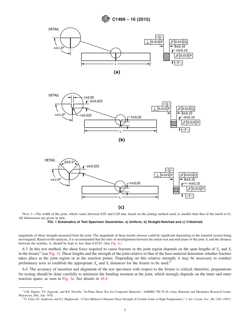
NOTE 1—The width of the joint, which varies between 0.05 and 0.20 mm, based on the joining method used, is smaller than that of the notch in b).
All dimensions are given in mm.
FIG. 1 Schematics of Test Specimen Geometries: a) Uniform, b) Straight-Notched and c) V-Notched
C1469 − 10 (2015)
FIG. 2 Schematic of Test Fixture
If the joint flexural strength is low (that is, <25 % of the
flexural strength of the base material), the recommended test
specimen geometry for shear strength testing of the joint is the
uniform test specimen shown in Fig. 1a. If the joint flexural
strength is moderate (that is, 25 to 50 % of the flexural strength
of the base material), the recommended test specimen geom-
etry for shear strength testing of the joint is the straight- or
V-notched test specimen shown in Fig. 1b and Fig. 1c,
respectively. If the joint flexural strength is high (>50 % of the
flexural strength of the base material) this test method should
not be used to measure shear strength of advanced ceramic
joints because very high contact stresses at the reaction points
willprovideahighprobabilityofinvalidtests(thatis,fractures
not at the joint).
4.2 The testing arrangement of this test method is asym-
metrical flexure, as illustrated by the force, shear and moment
diagramsinFig.3a,Fig.3b,andFig.3c,respectively.Notethat
the greatest shear exists over a region of 6 S/2 around the
i
centerline of the joint (see Fig. 3b). In addition, while the
moment is zero at the centerline of the joint, the maximum
moments occur at the inner reaction points (see Fig. 3c). The
pointsofmaximummomentsarewherethegreatestprobability
of fracture of the base material may occur if the joint flexural
strength, and therefore, joint shear strength is too high.
5. Significance and Use
5.1 Advanced ceramics are candidate materials for struc-
FIG. 3 Idealized a) Force, b) Shear, and c) Moment Diagrams for
tural applications requiring high degrees of wear and corrosion
Asymmetric Four-point Flexure, Where S and S Are the Outer
o i
resistance, often at elevated temperatures.
and Inner Reaction Span Distances, Respectively, and P is the
Applied Force
5.2 Joints are produced to enhance the performance and
applicability of materials. While the joints between similar
materials are generally made for manufacturing complex parts
and repairing components, those involving dissimilar materials usually are produced to exploit the unique properties of each
C1469 − 10 (2015)
constituent in the new component. Depending on the joining
process, the joint region may be the weakest part of the
component. Since under mixed-mode and shear loading, the
loadtransferacrossthejointrequiresreasonableshearstrength,
it is important that the quality and integrity of joint under
in-plane shear forces be quantified. Shear strength data are also
needed to monitor the development of new and improved
joining techniques.
5.3 Shear tests provide information on the strength and
deformation of materials under shear stresses.
5.4 This test method may be used for material development,
material comparison, quality assurance, characterization, and
design data generation.
5.5 For quality control purposes, results derived from stan-
dardized shear test specimens may be considered indicative of
the response of the material from which they were taken for
given primary processing conditions and post-processing heat
treatments.
NOTE 1—It is recommended that δ/h ratio in both notch types is less
than 0.0125.
6. Interferences FIG. 4 Schematic of Misalignment, δ, between the Joint Line and
Notch Root Shown for Straight—Notched Specimen
6.1 Fractures that initiate outside of the joint region may be
due to factors, such as localized stress concentrations, extra-
thebendingmomentatthejoint,whichstronglydependsonthe
neous stresses introduced by improper force transfer. Such
inner and outer reaction spans, as seen in Fig. 3c. See details in
fractures will constitute invalid tests.
10.4.
6.2 Since the joint width is typically small, that is, 0.05 to
6.5 Test environment (vacuum, inert gas, ambient air, etc.)
0.20 mm, the proper machining of the notches at the joint
including moisture content, for example, relative humidity,
region is very critical (see Fig. 1). Improper machining of the
may have an influence on the measured shear strength.
notches can lead to undesired fracture at the reaction points.
Conversely, testing can be conducted in environments and
Furthermore, nonsymmetrical machining of the nothces can be
testing modes and rates representative of service conditions to
decisive as to how the fracture occurs between the notches.
evaluate material performance under those conditions. When
NOTE 1—Finite element stress analysis of nonsymmetrical nothces
testing is conducted in uncontrolled ambient air with the
showed that when there is a misalignment between the notches and the
objective of evaluating maximum strength potential, relative
mid-plane of the joint, spurious normal (σ ) tensile stresses are generated
x
humidity and temperature must be monitored and reported.
at the notches which tend to “tear” the joint and would artificially affect
Testing at humidity levels >65 % RH is not recommended and
(reduce) the magnitude of shear strength measured from the joint. The
magnitude of these tensile stresses could be significant depending on the any deviations from this recommendation shall be reported.
material system being investigated. Based on this analysis, it is recom-
mended that the ratio of misalignment between the notch root and 7. Apparatus
mid-plane of the joint, δ, and the distance between the notches, h, should
7.1 Testing Machines—The testing machine shall be in
be kept to less than 0.0125. (See Fig. 4.)
conformancewithPracticesE4.Theforcesusedindetermining
6.3 In this test method, the shear force required to cause
shear strength shall be accurate within 61 % at any force
fracture in the joint region depends on the span lengths of S
o
within the selected force range of the testing machine as
and S inthefixture (seeFig.3).Theselengthsandthestrength
i
defined in Practices E4.
of the joint relative to that of the base material determine
7.2 Data Acquisition—At a minimum, autographic records
whether fracture takes place at the joint region or at the
of applied force and cross-head displacement versus time shall
reaction points. Depending on this relative strength, it may be
be obtained. Either analog chart recorders or digital data
necessary to conduct preliminary tests to establish the appro-
acquisition systems may be used for this purpose although a
priate S and S distances for the fixture to be used.
o i
digital record is recommended for ease of later data analysis.
6.4 The accuracy of insertion and alignment of the test
Ideally, an analog chart recorder or plotter should be used in
specimen with respect to the fixture is critical; therefore,
conjunction with the digital data acquisition system to provide
preparations for testing should be done carefully to minimize
an immediate record of the test as a supplement to the digital
record. Recording devices shall be accurate to 61 % of full
scale and shall have a minimum data acquisition rate of 10 Hz
J.M. Slepetz, T.F. Zagaeski, and R.F. Novello, “In-Plane Shear Test for
with a response of 50 Hz deemed more than sufficient.
Composite Materials,” AMMRC-TR-78-30, Army Materials and Mechanics Re-
search Center, Watertown, MA, July 1978.
7.3 Dimension-Measuring Devices—Micrometers and other
Ö. Ünal, I.E.Anderson, and S.I. Maghsoodi, “ATest Method to Measure Shear
devices used for measuring linear dimensions must be accurate
Strength of Ceramic Joints at High Temperatures,” J. Am. Ceram. Soc., 80, 1281
(1997). and precise to at least 0.01 mm.
C1469 − 10 (2015)
7.4 Combination Square—Used to draw perpendicular lines joint (Fig. 1b and Fig. 1c). Moreover, the depth of each of the
to specimen axis at the locations of inner loading points. The notches shall be one fourth of the overall height of the test
tolerance must be within 0.5°. specimen (H/4). While the drawings in Fig. 1 show the
tolerances for the test specimens, Table 2 shows symbols,
7.5 Test Fixture—The test fixture consists of top and bottom
nomenclature and recommended dimensions for the test speci-
sections, reaction-pins, and a force transfer ball, as shown
men.Ifnecessary,thetestspecimendimensions,thatis,length,
schematically in Fig. 2. The bottom section is placed on a
height, width and notch depth, if applicable) can be adjusted to
stationary base, for example, a compression plate
...
This document is not an ASTM standard and is intended only to provide the user of an ASTM standard an indication of what changes have been made to the previous version. Because
it may not be technically possible to adequately depict all changes accurately, ASTM recommends that users consult prior editions as appropriate. In all cases only the current version
of the standard as published by ASTM is to be considered the official document.
Designation: C1469 − 10 C1469 − 10 (Reapproved 2015)
Standard Test Method for
Shear Strength of Joints of Advanced Ceramics at Ambient
Temperature
This standard is issued under the fixed designation C1469; the number immediately following the designation indicates the year of
original adoption or, in the case of revision, the year of last revision. A number in parentheses indicates the year of last reapproval. A
superscript epsilon (´) indicates an editorial change since the last revision or reapproval.
1. Scope
1.1 This test method covers the determination of shear strength of joints in advanced ceramics at ambient temperature. Test
specimen geometries, test specimen fabrication methods, testing modes (that is, force or displacement control), testing rates (that
is, force or displacement rate), data collection, and reporting procedures are addressed.
1.2 This test method is used to measure shear strength of ceramic joints in test specimens extracted from larger joined pieces
by machining. Test specimens fabricated in this way are not expected to warp due to the relaxation of residual stresses but are
expected to be much straighter and more uniform dimensionally than butt-jointed test specimens prepared by joining two halves,
which are not recommended. In addition, this test method is intended for joints, which have either low or intermediate strengths
with respect to the substrate material to be joined. Joints with high strengths should not be tested by this test method because of
the high probability of invalid tests resulting from fractures initiating at the reaction points rather than in the joint. Determination
of the shear strength of joints using this test method is appropriate particularly for advanced ceramic matrix composite materials
but also may be useful for monolithic advanced ceramic materials.
1.3 Values expressed in this test method are in accordance with the International System of Units (SI) and IEEE/ASTM SI 10
.
1.4 This test method does not purport to address the safety problems associated with its use. It is the responsibility of the user
of this test method to establish appropriate safety and health practices and determine the applicability of regulatory limitations
prior to use. Specific precautionary statements are noted in 8.1 and 8.2.
2. Referenced Documents
2.1 ASTM Standards:
C1145 Terminology of Advanced Ceramics
C1161 Test Method for Flexural Strength of Advanced Ceramics at Ambient Temperature
C1211 Test Method for Flexural Strength of Advanced Ceramics at Elevated Temperatures
C1275 Test Method for Monotonic Tensile Behavior of Continuous Fiber-Reinforced Advanced Ceramics with Solid
Rectangular Cross-Section Test Specimens at Ambient Temperature
C1341 Test Method for Flexural Properties of Continuous Fiber-Reinforced Advanced Ceramic Composites
D3878 Terminology for Composite Materials
D5379/D5379M Test Method for Shear Properties of Composite Materials by the V-Notched Beam Method
E4 Practices for Force Verification of Testing Machines
E6 Terminology Relating to Methods of Mechanical Testing
E122 Practice for Calculating Sample Size to Estimate, With Specified Precision, the Average for a Characteristic of a Lot or
Process
E337 Test Method for Measuring Humidity with a Psychrometer (the Measurement of Wet- and Dry-Bulb Temperatures)
IEEE/ASTM SI 10 American National Standard for Use of the International System of Units (SI): The Modern Metric System
3. Terminology
3.1 Definitions:
This test method is under the jurisdiction of ASTM Committee C28 on Advanced Ceramics and is the direct responsibility of Subcommittee C28.07 on Ceramic Matrix
Composites.
Current edition approved Dec. 1, 2010Jan. 1, 2015. Published January 2011April 2015. Originally approved in 2000. Last previous edition approved in 20052010 as
C1469 – 00C1469 – 10. (2005). DOI: 10.1520/C1469-10.10.1520/C1469-10R15.
For referenced ASTM standards, visit the ASTM website, www.astm.org, or contact ASTM Customer Service at service@astm.org. For Annual Book of ASTM Standards
volume information, refer to the standard’s Document Summary page on the ASTM website.
Copyright © ASTM International, 100 Barr Harbor Drive, PO Box C700, West Conshohocken, PA 19428-2959. United States
C1469 − 10 (2015)
3.1.1 The definitions of terms relating to shear strength testing appearing in Terminology E6, to advanced ceramics appearing
in Terminologies C1145 and D3878 apply to the terms used in this test method. Additional terms used in conjunction with this test
method are defined as follows.
3.1.2 advanced ceramic, n—highly-engineered, high-performance predominately nonmetallic, inorganic, ceramic material
having specific functional attributes. C1145
3.1.3 breaking force [F], n—force at which fracture occurs.
3.1.4 ceramic matrix composite, n—material consisting of two or more materials (insoluble in one another), in which the major,
continuous component (matrix component) is a ceramic while the secondary component(s) may be ceramic, glass-ceramic, glass,
metal, or organic in nature. These components are combined on macroscale to form a useful engineering material possessing
certain properties or behavior not possessed by the individual constituents. C1275
3.1.5 joining, n—controlled formation of chemical, or mechanical bond, or both, between similar or dissimilar materials.
3.1.6 shear strength [F/L ], n—maximum shear stress that a material is capable of sustaining. Shear strength is calculated from
breaking force in shear and shear area.
4. Summary of Test Method
4.1 This test method describes an asymmetrical four-point flexure test method to determine shear strengths of advanced ceramic
joints. Test specimens and test setup are shown schematically in Fig. 1 and Fig. 2, respectively. Selection of the test specimen
geometry depends on the bond strength of the joint, which may be determined by preparing longer test specimens of the same
cross-section and using a standard four-point flexural strength test, for example, Test Method C1161 for monolithic advanced
ceramic base material and Test Method C1341 for composite advanced ceramic base material. If the joint flexural strength is low
(that is, <25 % of the flexural strength of the base material), the recommended test specimen geometry for shear strength testing
of the joint is the uniform test specimen shown in Fig. 1a. If the joint flexural strength is moderate (that is, 25 to 50 % of the flexural
strength of the base material), the recommended test specimen geometry for shear strength testing of the joint is the straight- or
V-notched test specimen shown in Fig. 1b and Fig. 1c, respectively. If the joint flexural strength is high (>50 % of the flexural
strength of the base material) this test method should not be used to measure shear strength of advanced ceramic joints because
very high contact stresses at the reaction points will provide a high probability of invalid tests (that is, fractures not at the joint).
4.2 The testing arrangement of this test method is asymmetrical flexure, as illustrated by the force, shear and moment diagrams
in Fig. 3a, Fig. 3b, and Fig. 3c, respectively. Note that the greatest shear exists over a region of 6 S /2 around the centerline of
i
the joint (see Fig. 3b). In addition, while the moment is zero at the centerline of the joint, the maximum moments occur at the inner
reaction points (see Fig. 3c). The points of maximum moments are where the greatest probability of fracture of the base material
may occur if the joint flexural strength, and therefore, joint shear strength is too high.
5. Significance and Use
5.1 Advanced ceramics are candidate materials for structural applications requiring high degrees of wear and corrosion
resistance, often at elevated temperatures.
5.2 Joints are produced to enhance the performance and applicability of materials. While the joints between similar materials
are generally made for manufacturing complex parts and repairing components, those involving dissimilar materials usually are
produced to exploit the unique properties of each constituent in the new component. Depending on the joining process, the joint
region may be the weakest part of the component. Since under mixed-mode and shear loading, the load transfer across the joint
requires reasonable shear strength, it is important that the quality and integrity of joint under in-plane shear forces be quantified.
Shear strength data are also needed to monitor the development of new and improved joining techniques.
5.3 Shear tests provide information on the strength and deformation of materials under shear stresses.
5.4 This test method may be used for material development, material comparison, quality assurance, characterization, and
design data generation.
5.5 For quality control purposes, results derived from standardized shear test specimens may be considered indicative of the
response of the material from which they were taken for given primary processing conditions and post-processing heat treatments.
6. Interferences
6.1 Fractures that initiate outside of the joint region may be due to factors, such as localized stress concentrations, extraneous
stresses introduced by improper force transfer. Such fractures will constitute invalid tests.
6.2 Since the joint width is typically small, that is, 0.05 to 0.20 mm, the proper machining of the notches at the joint region is
very critical (see Fig. 1). Improper machining of the notches can lead to undesired fracture at the reaction points. Furthermore,
nonsymmetrical machining of the nothces can be decisive as to how the fracture occurs between the notches.
NOTE 1—Finite element stress analysis of nonsymmetrical nothces showed that when there is a misalignment between the notches and the mid-plane
of the joint, spurious normal (σ ) tensile stresses are generated at the notches which tend to “tear” the joint and would artificially affect (reduce) the
x
C1469 − 10 (2015)
NOTE 1—The width of the joint, which varies between 0.05 and 0.20 mm, based on the joining method used, is smaller than that of the notch in b).
All dimensions are given in mm.
FIG. 1 Schematics of Test Specimen Geometries: a) Uniform, b) Straight-Notched and c) V-Notched
magnitude of shear strength measured from the joint. The magnitude of these tensile stresses could be significant depending on the material system being
investigated. Based on this analysis, it is recommended that the ratio of misalignment between the notch root and mid-plane of the joint, δ, and the distance
between the notches, h, should be kept to less than 0.0125. (See Fig. 4.)
6.3 In this test method, the shear force required to cause fracture in the joint region depends on the span lengths of S and S
o i
in the fixture (see Fig. 3). These lengths and the strength of the joint relative to that of the base material determine whether fracture
takes place at the joint region or at the reaction points. Depending on this relative strength, it may be necessary to conduct
preliminary tests to establish the appropriate S and S distances for the fixture to be used.
o i
6.4 The accuracy of insertion and alignment of the test specimen with respect to the fixture is critical; therefore, preparations
for testing should be done carefully to minimize the bending moment at the joint, which strongly depends on the inner and outer
reaction spans, as seen in Fig. 3c. See details in 10.4.
J.M. Slepetz, T.F. Zagaeski, and R.F. Novello, “In-Plane Shear Test for Composite Materials,” AMMRC-TR-78-30, Army Materials and Mechanics Research Center,
Watertown, MA, July 1978.
Ö. Ünal, I.E. Anderson, and S.I. Maghsoodi, “A Test Method to Measure Shear Strength of Ceramic Joints at High Temperatures,” J. Am. Ceram. Soc., 80, 1281 (1997).
C1469 − 10 (2015)
FIG. 2 Schematic of Test Fixture
FIG. 3 Idealized a) Force, b) Shear, and c) Moment Diagrams for Asymmetric Four-point Flexure, Where S and S Are the Outer and In-
o i
ner Reaction Span Distances, Respectively, and P is the Applied Force
6.5 Test environment (vacuum, inert gas, ambient air, etc.) including moisture content, for example, relative humidity, may have
an influence on the measured shear strength. Conversely, testing can be conducted in environments and testing modes and rates
representative of service conditions to evaluate material performance under those conditions. When testing is conducted in
C1469 − 10 (2015)
NOTE 1—It is recommended that δ/h ratio in both notch types is less than 0.0125.
FIG. 4 Schematic of Misalignment, δ, between the Joint Line and Notch Root Shown for Straight—Notched Specimen
uncontrolled ambient air with the objective of evaluating maximum strength potential, relative humidity and temperature must be
monitored and reported. Testing at humidity levels >65 % RH is not recommended and any deviations from this recommendation
shall be reported.
7. Apparatus
7.1 Testing Machines—The testing machine shall be in conformance with Practices E4. The forces used in determining shear
strength shall be accurate within 61 % at any force within the selected force range of the testing machine as defined in Practices
E4.
7.2 Data Acquisition—At a minimum, autographic records of applied force and cross-head displacement versus time shall be
obtained. Either analog chart recorders or digital data acquisition systems may be used for this purpose although a digital record
is recommended for ease of later data analysis. Ideally, an analog chart recorder or plotter should be used in conjunction with the
digital data acquisition system to provide an immediate record of the test as a supplement to the digital record. Recording devices
shall be accurate to 61 % of full scale and shall have a minimum data acquisition rate of 10 Hz with a response of 50 Hz deemed
more than sufficient.
7.3 Dimension-Measuring Devices—Micrometers and other devices used for measuring linear dimensions must be accurate and
precise to at least 0.01 mm.
7.4 Combination Square—Used to draw perpendicular lines to specimen axis at the locations of inner loading points. The
tolerance must be within 0.5°.
7.5 Test Fixture—The test fixture consists of top and bottom sections, reaction-pins, and a force transfer ball, as shown
schematically in Fig. 2. The bottom section is placed on a stationary base, for example, a compres
...
Questions, Comments and Discussion
Ask us and Technical Secretary will try to provide an answer. You can facilitate discussion about the standard in here.