


ASTM B854-98(2016)
(Guide)Standard Guide for Measuring Electrical Contact Intermittences
Standard Guide for Measuring Electrical Contact Intermittences
SIGNIFICANCE AND USE
4.1 This guide suggests techniques to evaluate intermittences in a contact pair while it is subjected to simulated or actual environmental stress. Such measurements are a valuable tool in predicting circuit performance under these stress conditions and in diagnosing observed problems in circuit function under such conditions.
4.2 This document is intended to provide some general guidance on the best available practices for detecting, quantifying, characterizing and reporting short duration intermittences in circuits containing electrical contacts. Certain environmental stresses such as mechanical shock, vibration or temperature change may cause intermittences. These measurement procedures include methods applicable to contacts operating under various conditions in testing or in service.
4.3 Practice B615 defines methods for measuring electrical contact noise in sliding electrical contacts. In contrast Guide B854 provides guidance to the various methods for measuring similar phenomena in static contacts.
SCOPE
1.1 The techniques described in this guide apply to electrical circuits that include one or more electrical contacts in devices such as slip rings, separable connectors, electromechanical relays or closed switch contacts. The user should determine applicability for other devices.
1.2 The range of techniques described apply to circuit discontinuities (intermittences) of durations ranging from approximately 10 nanoseconds to several seconds and of sufficient magnitude to cause alteration of the circuit function. Extension of the guide to shorter duration events may be possible with suitable instrumentation. Events of longer duration may be monitored by techniques for dc measurements such as those described in Test Methods B539 or by adaptation of methods described in this guide.
1.3 The techniques described in this guide apply to electrical circuits carrying currents typical of signal circuits. Such currents are generally less than 100 ma. Extension of these techniques to circuits carrying larger currents may be possible, but the user should evaluate applicability first.
1.4 This standard does not purport to address all of the safety concerns, if any, associated with its use. It is the responsibility of the user of this standard to become familiar with all hazards including those identified in the appropriate Safety Data Sheet (SDS) for this product/material as provided by the manufacturer, to establish appropriate safety and health practices, and determine the applicability of regulatory limitations prior to use.
General Information
Buy Standard
Standards Content (Sample)
NOTICE: This standard has either been superseded and replaced by a new version or withdrawn.
Contact ASTM International (www.astm.org) for the latest information
Designation: B854 − 98 (Reapproved 2016)
Standard Guide for
Measuring Electrical Contact Intermittences
This standard is issued under the fixed designation B854; the number immediately following the designation indicates the year of
original adoption or, in the case of revision, the year of last revision. A number in parentheses indicates the year of last reapproval. A
superscript epsilon (´) indicates an editorial change since the last revision or reapproval.
This standard has been approved for use by agencies of the U.S. Department of Defense.
1. Scope B539 Test Methods for Measuring Resistance of Electrical
Connections (Static Contacts)
1.1 The techniques described in this guide apply to electri-
B542 Terminology Relating to Electrical Contacts and Their
cal circuits that include one or more electrical contacts in
Use
devices such as slip rings, separable connectors, electrome-
B615 Practice for Measuring Electrical Contact Noise in
chanical relays or closed switch contacts. The user should
Sliding Electrical Contacts
determine applicability for other devices.
B878 Test Method for Nanosecond Event Detection for
1.2 The range of techniques described apply to circuit
Electrical Contacts and Connectors
discontinuities (intermittences) of durations ranging from ap-
2.2 Other Documents:
proximately 10 nanoseconds to several seconds and of suffi-
IEC Publication 512 Test 2e Contact Disturbance
cient magnitude to cause alteration of the circuit function.
EIA-364-46 Continuity Test Procedure for Electrical Con-
Extension of the guide to shorter duration events may be
nectors
possible with suitable instrumentation. Events of longer dura-
tion may be monitored by techniques for dc measurements 3. Terminology
such as those described inTest Methods B539 or by adaptation
3.1 Terms relevant to this guide are defined in Terminology
of methods described in this guide.
B542 except as noted in the following section.
1.3 The techniques described in this guide apply to electri-
3.2 Definitions of Terms Specific to This Standard:
cal circuits carrying currents typical of signal circuits. Such
3.2.1 intermittence, n—a transient increase in the voltage
currents are generally less than 100 ma. Extension of these
drop across a pair of electrical contacts.
techniques to circuits carrying larger currents may be possible,
but the user should evaluate applicability first.
4. Significance and Use
1.4 This standard does not purport to address all of the
4.1 This guide suggests techniques to evaluate intermit-
safety concerns, if any, associated with its use. It is the
tences in a contact pair while it is subjected to simulated or
responsibility of the user of this standard to become familiar
actual environmental stress. Such measurements are a valuable
with all hazards including those identified in the appropriate
tool in predicting circuit performance under these stress
Safety Data Sheet (SDS) for this product/material as provided
conditions and in diagnosing observed problems in circuit
by the manufacturer, to establish appropriate safety and health
function under such conditions.
practices, and determine the applicability of regulatory limi-
4.2 This document is intended to provide some general
tations prior to use.
guidance on the best available practices for detecting,
quantifying, characterizing and reporting short duration inter-
2. Referenced Documents
mittences in circuits containing electrical contacts. Certain
2.1 ASTM Standards:
environmental stresses such as mechanical shock, vibration or
temperature change may cause intermittences. These measure-
ment procedures include methods applicable to contacts oper-
ating under various conditions in testing or in service.
This guide is under the jurisdiction of ASTM Committee B02 on Nonferrous
Metals and Alloys and is the direct responsibility of Subcommittee B02.11 on
4.3 Practice B615 defines methods for measuring electrical
Electrical Contact Test Methods.
contact noise in sliding electrical contacts. In contrast Guide
Current edition approved May 1, 2016. Published May 2016. Originally
ɛ1
approved in 1998. Last previous edition approved in 2010 as B854 – 98 (2010) .
DOI: 10.1520/B0854-98R16.
2 3
For referenced ASTM standards, visit the ASTM website, www.astm.org, or Available from American National Standards Institute (ANSI), 25 W. 43rd St.,
contact ASTM Customer Service at service@astm.org. For Annual Book of ASTM 4th Floor, New York, NY 10036, http://www.ansi.org.
Standards volume information, refer to the standard’s Document Summary page on Available from Electronic IndustriesAssociation, 2001 PennsylvaniaAve NW,
the ASTM website. Washington D.C. 20006.
Copyright © ASTM International, 100 Barr Harbor Drive, PO Box C700, West Conshohocken, PA 19428-2959. United States
B854 − 98 (2016)
TABLE 1 Comparison of Methods of Monitoring Electrical Contact Intermittences
Typical Number Typical Event Possible
Method
of Channels Characterization Advantages
Oscilloscope 1, 2 or 4 ∆V vs time Detailed characterization of each event
Custom Circuitry 1 per circuit Presence or absence of one or more events during a Ability to closely model actual circuit conditions,
preselected monitoring interval, such events defined allows use of various technologies in the transmitting
as above a preselected threshold of ∆R and duration, and receiving devices
the number of events during the interval may or may
not be recorded.
Event Detector 1 to 64 Presence or absence of one or more events during a Multichannel capability, selection of thresholds for
preselected monitoring interval, such events defined
events to be counted
as above a preselected threshold of ∆R and duration,
but the number of events during the interval is not
recorded.
Bit Error Rate 1 Ratio of errors to number of bits transmitted The format of the results is readily applicable to
ranking of interconnection devices with respect to
transmission quality for a specific signal format
following list covers questions that the user should answer
before selecting a test method.
6.1.1 What is the definition of an intermittence in the
intended application? For example, what resistance change
over what time interval constitutes an intermittence, or what
error occurs if the contact resistance changes, or what other
definition is appropriate for the intended purpose of the test
results?
6.1.2 Is it necessary to monitor more than one contact
simultaneously?Ifso,isitacceptabletoconnectthecontactsin
series? If contacts cannot be connected in series, how many
FIG. 1 Schematic Representation of Oscilloscope Method
contacts must be measured simultaneously?
6.2 Test results should be reported in a format appropriate
B854 provides guidance to the various methods for measuring
for the application and consistent with the format supplied by
similar phenomena in static contacts.
the test instrument.
5. Apparatus
6.3 Oscilloscope—In this method, an oscilloscope is wired
5.1 General Comments—The apparatus required varies de-
to monitor the potential across the contact(s) of interest while
pending upon the technique selected and the parameters (such
a signal is passed through the contacts. Standards such as IEC
as duration and magnitude) of the intermittence that the user
Publication 512, Test 2e or EIA-364-46 are often implemented
wants to detect. In general, the cabling must be capable of
using this method. Practice B615 provides a specific circuit
carrying signals of the speed to be detected in the study, and
that uses this method. Examples of the use of this method are
must be isolated from sources of noise that may cause false
shown in the reference by Currence and Rhoades.
indications.
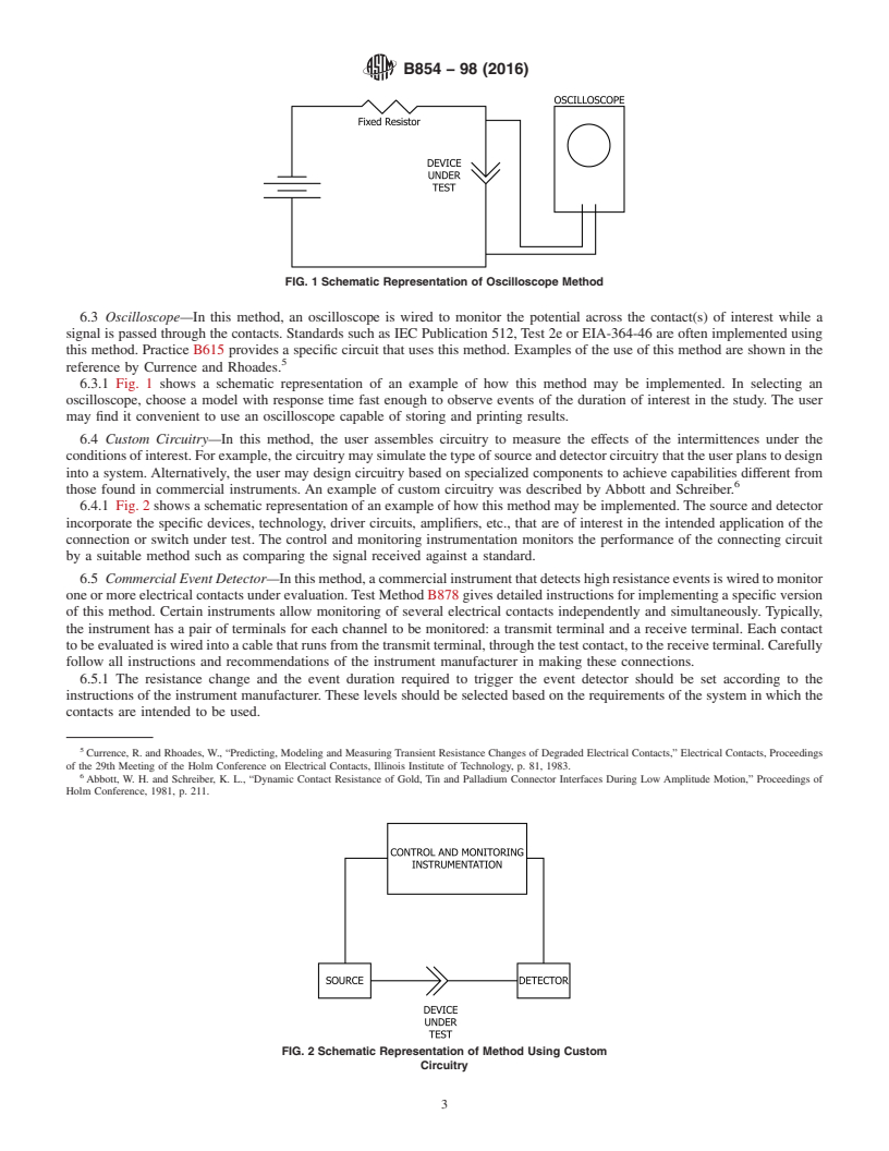
6.3.1 Fig. 1 shows a schematic representation of an example
5.2 Special Precautions for Measurements Involving Events
of how this method may be implemented. In selecting an
Less than 1 Microsecond in Duration—Detection of events of
oscilloscope,chooseamodelwithresponsetimefastenoughto
duration less than 1 microsecond will require special attention
observe events of the duration of interest in the study. The user
to the wiring of the detection circuits and instrumentation.
mayfinditconvenienttouseanoscilloscopecapableofstoring
Such attention may include using coaxial cable, shielding the
and printing results.
apparatus from interferences and minimizing cable lengths.
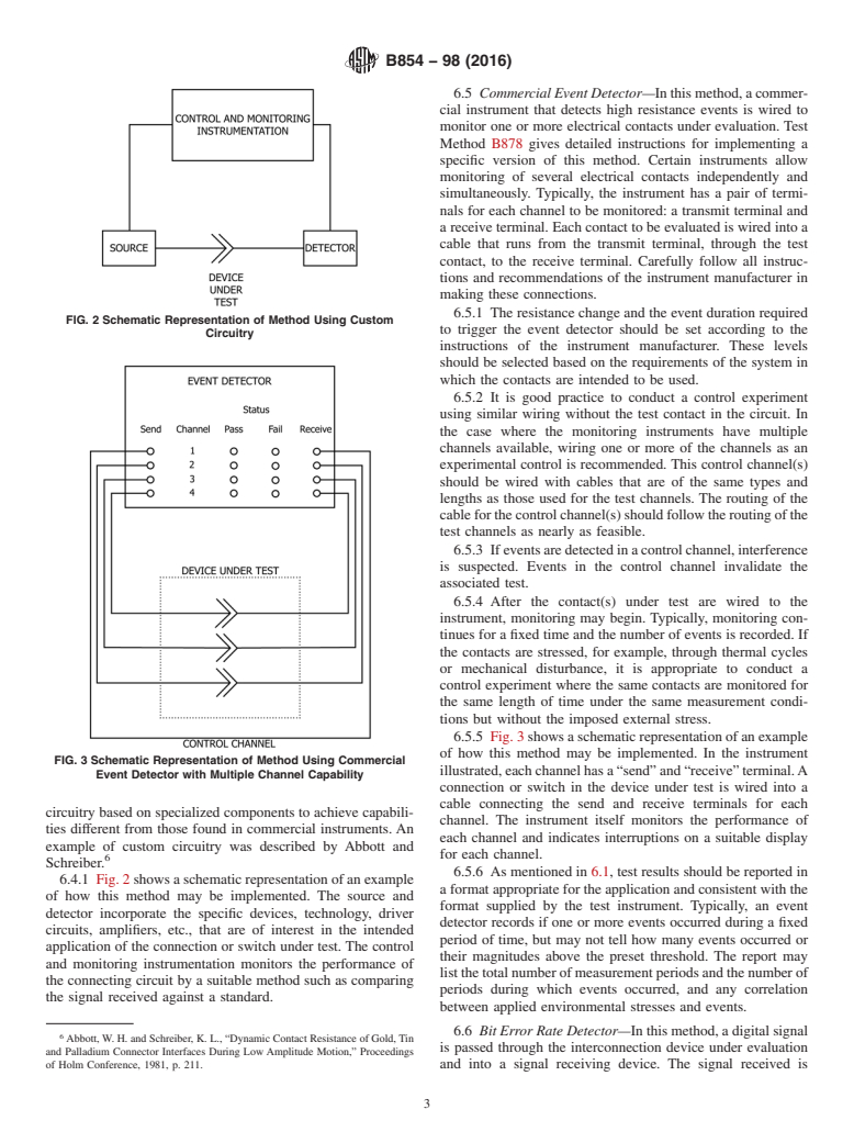
6.4 Custom Circuitry—In this method, the user assembles
5.3 Specific Apparatus—The apparatus required will vary
circuitry to measure the effects of the intermittences under the
depending upon the measurement method selected and the
conditions of interest. For example, the circuitry may simulate
environmental stresses imposed during the test.
the type of source and detector circuitry that the user plans to
design into a system. Alternatively, the user may design
6. Procedure
6.1 General Comments—The following sections describe,
in general terms, several methods that have been used to de
...
This document is not an ASTM standard and is intended only to provide the user of an ASTM standard an indication of what changes have been made to the previous version. Because
it may not be technically possible to adequately depict all changes accurately, ASTM recommends that users consult prior editions as appropriate. In all cases only the current version
of the standard as published by ASTM is to be considered the official document.
´1
Designation: B854 − 98 (Reapproved 2010) B854 − 98 (Reapproved 2016)
Standard Guide for
Measuring Electrical Contact Intermittences
This standard is issued under the fixed designation B854; the number immediately following the designation indicates the year of
original adoption or, in the case of revision, the year of last revision. A number in parentheses indicates the year of last reapproval. A
superscript epsilon (´) indicates an editorial change since the last revision or reapproval.
ε NOTE—Footnotes 7 and 8 were removed editorially in October 2010.
This standard has been approved for use by agencies of the U.S. Department of Defense.
1. Scope
1.1 The techniques described in this guide apply to electrical circuits that include one or more electrical contacts in devices such
as slip rings, separable connectors, electromechanical relays or closed switch contacts. The user should determine applicability for
other devices.
1.2 The range of techniques described apply to circuit discontinuities (intermittences) of durations ranging from approximately
10 nanoseconds to several seconds and of sufficient magnitude to cause alteration of the circuit function. Extension of the guide
to shorter duration events may be possible with suitable instrumentation. Events of longer duration may be monitored by
techniques for dc measurements such as those described in Test Methods B539 or by adaptation of methods described in this guide.
1.3 The techniques described in this guide apply to electrical circuits carrying currents typical of signal circuits. Such currents
are generally less than 100 ma. Extension of these techniques to circuits carrying larger currents may be possible, but the user
should evaluate applicability first.
1.4 This standard does not purport to address all of the safety concerns, if any, associated with its use. It is the responsibility
of the user of this standard to become familiar with all hazards including those identified in the appropriate Material Safety Data
Sheet (MSDS)(SDS) for this product/material as provided by the manufacturer, to establish appropriate safety and health practices,
and determine the applicability of regulatory limitations prior to use.
2. Referenced Documents
2.1 ASTM Standards:
B539 Test Methods for Measuring Resistance of Electrical Connections (Static Contacts)
B542 Terminology Relating to Electrical Contacts and Their Use
B615 Practice for Measuring Electrical Contact Noise in Sliding Electrical Contacts
B878 Test Method for Nanosecond Event Detection for Electrical Contacts and Connectors
2.2 Other Documents:
IEC Publication 512 Test 2e Contact Disturbance
EIA-364-46 Continuity Test Procedure for Electrical Connectors
3. Terminology
3.1 Terms relevant to this guide are defined in Terminology B542 except as noted in the following section.
3.2 Definitions of Terms Specific to This Standard:
3.2.1 intermittence, n—a transient increase in the voltage drop across a pair of electrical contacts.
This guide is under the jurisdiction of ASTM Committee B02 on Nonferrous Metals and Alloys and is the direct responsibility of Subcommittee B02.11 on Electrical
Contact Test Methods.
Current edition approved Oct. 1, 2010May 1, 2016. Published October 2010May 2016. Originally approved in 1998. Last previous edition approved in 20042010 as
ɛ1
B854 – 98 (2004).(2010) . DOI: 10.1520/B0854-98R10E01.10.1520/B0854-98R16.
For referenced ASTM standards, visit the ASTM website, www.astm.org, or contact ASTM Customer Service at service@astm.org. For Annual Book of ASTM Standards
volume information, refer to the standard’s Document Summary page on the ASTM website.
Available from American National Standards Institute (ANSI), 25 W. 43rd St., 4th Floor, New York, NY 10036, http://www.ansi.org.
Available from Electronic Industries Association, 2001 Pennsylvania Ave NW, Washington D.C. 20006.
Copyright © ASTM International, 100 Barr Harbor Drive, PO Box C700, West Conshohocken, PA 19428-2959. United States
B854 − 98 (2016)
4. Significance and Use
4.1 This guide suggests techniques to evaluate intermittences in a contact pair while it is subjected to simulated or actual
environmental stress. Such measurements are a valuable tool in predicting circuit performance under these stress conditions and
in diagnosing observed problems in circuit function under such conditions.
4.2 This document is intended to provide some general guidance on the best available practices for detecting, quantifying,
characterizing and reporting short duration intermittences in circuits containing electrical contacts. Certain environmental stresses
such as mechanical shock, vibration or temperature change may cause intermittences. These measurement procedures include
methods applicable to contacts operating under various conditions in testing or in service.
4.3 Practice B615 defines methods for measuring electrical contact noise in sliding electrical contacts. In contrast Guide B854
provides guidance to the various methods for measuring similar phenomena in static contacts.
5. Apparatus
5.1 General Comments—The apparatus required varies depending upon the technique selected and the parameters (such as
duration and magnitude) of the intermittence that the user wants to detect. In general, the cabling must be capable of carrying
signals of the speed to be detected in the study, and must be isolated from sources of noise that may cause false indications.
5.2 Special Precautions for Measurements Involving Events Less than 1 Microsecond in Duration—Detection of events of
duration less than 1 microsecond will require special attention to the wiring of the detection circuits and instrumentation. Such
attention may include using coaxial cable, shielding the apparatus from interferences and minimizing cable lengths.
5.3 Specific Apparatus—The apparatus required will vary depending upon the measurement method selected and the
environmental stresses imposed during the test.
6. Procedure
6.1 General Comments—The following sections describe, in general terms, several methods that have been used to detect or
measure contact intermittences. The user should select an appropriate method and adapt it as required. Table 1 presents a
comparison of the attributes of the various methods. The following list covers questions that the user should answer before
selecting a test method.
6.1.1 What is the definition of an intermittence in the intended application? For example, what resistance change over what time
interval constitutes an intermittence, or what error occurs if the contact resistance changes, or what other definition is appropriate
for the intended purpose of the test results?
6.1.2 Is it necessary to monitor more than one contact simultaneously? If so, is it acceptable to connect the contacts in series?
If contacts cannot be connected in series, how many contacts must be measured simultaneously?
6.2 Test results should be reported in a format appropriate for the application and consistent with the format supplied by the
test instrument.
TABLE 1 Comparison of Methods of Monitoring Electrical Contact Intermittences
Typical Number Typical Event Possible
Method
of Channels Characterization Advantages
Oscilloscope 1, 2 or 4 ΔV vs time Detailed characterization of each event
Oscilloscope 1, 2 or 4 ΔV vs time Detailed characterization of each event
Custom Circuitry 1 per circuit Presence or absence of one or more events during a Ability to closely model actual circuit conditions,
preselected monitoring interval, such events defined allows use of various technologies in the transmitting
as above a preselected threshold of ΔR and duration, and receiving devices
the number of events during the interval may or may
not be recorded.
Event Detector 1 to 64 Presence or absence of one or more events during a Multichannel capability, selection of thresholds for
preselected monitoring interval, such events defined events to be counted
as above a preselected threshold of ΔR and duration,
but the number of events during the interval is not
recorded.
Bit Error Rate 1 Ratio of errors to number of bits transmitted The format of the results is readily applicable to
ranking of interconnection devices with respect to
transmission quality for a specific signal format
B854 − 98 (2016)
FIG. 1 Schematic Representation of Oscilloscope Method
6.3 Oscilloscope—In this method, an oscilloscope is wired to monitor the potential across the contact(s) of interest while a
signal is passed through the contacts. Standards such as IEC Publication 512, Test 2e or EIA-364-46 are often implemented using
this method. Practice B615 provides a specific circuit that uses this method. Examples of the use of this method are shown in the
reference by Currence and Rhoades.
6.3.1 Fig. 1 shows a schematic representation of an example of how this method may be implemented. In selecting an
oscilloscope, choose a model with response time fast enough t
...
Questions, Comments and Discussion
Ask us and Technical Secretary will try to provide an answer. You can facilitate discussion about the standard in here.