


ASTM D5766/D5766M-11(2018)
(Test Method)Standard Test Method for Open-Hole Tensile Strength of Polymer Matrix Composite Laminates
Standard Test Method for Open-Hole Tensile Strength of Polymer Matrix Composite Laminates
SIGNIFICANCE AND USE
5.1 This test method is designed to produce notched tensile strength data for structural design allowables, material specifications, research and development, and quality assurance. Factors that influence the notched tensile strength and should therefore be reported include the following: material, methods of material fabrication, accuracy of lay-up, laminate stacking sequence and overall thickness, specimen geometry (including hole diameter, diameter-to-thickness ratio, and width-to-diameter ratio), specimen preparation (especially of the hole), specimen conditioning, environment of testing, specimen alignment and gripping, speed of testing, time at temperature, void content, and volume percent reinforcement. Properties that may be derived from this test method include the following:
5.1.1 Open-hole (notched) tensile strength (OHT).
SCOPE
1.1 This test method determines the open-hole tensile strength of multidirectional polymer matrix composite laminates reinforced by high-modulus fibers. The composite material forms are limited to continuous-fiber or discontinuous-fiber (tape or fabric, or both) reinforced composites in which the laminate is balanced and symmetric with respect to the test direction. The range of acceptable test laminates and thicknesses are described in 8.2.1.
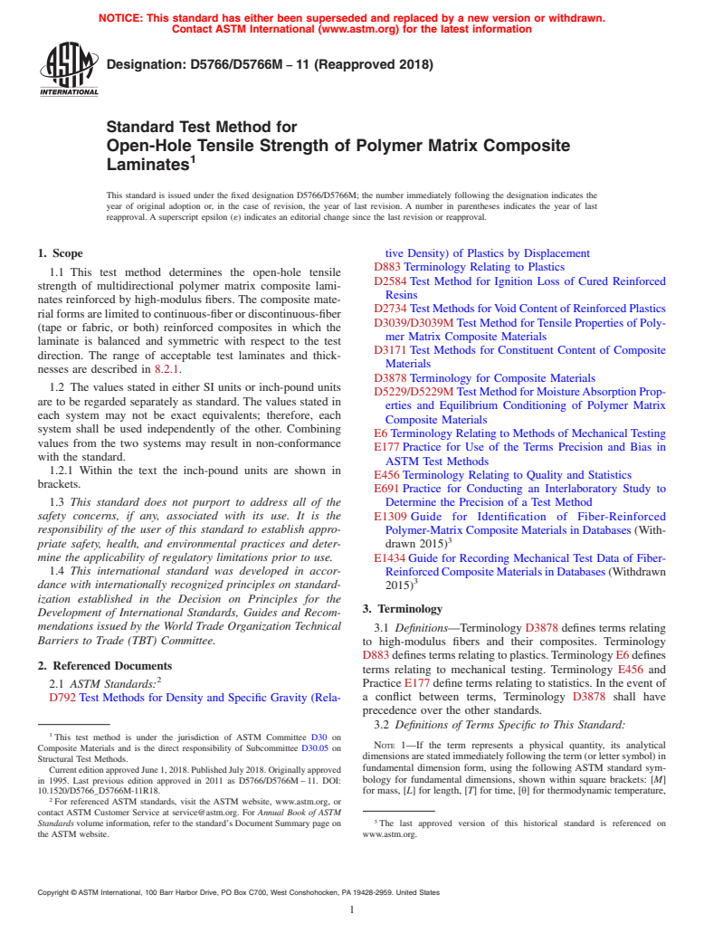
1.2 The values stated in either SI units or inch-pound units are to be regarded separately as standard. The values stated in each system may not be exact equivalents; therefore, each system shall be used independently of the other. Combining values from the two systems may result in non-conformance with the standard.
1.2.1 Within the text the inch-pound units are shown in brackets.
1.3 This standard does not purport to address all of the safety concerns, if any, associated with its use. It is the responsibility of the user of this standard to establish appropriate safety, health, and environmental practices and determine the applicability of regulatory limitations prior to use.
1.4 This international standard was developed in accordance with internationally recognized principles on standardization established in the Decision on Principles for the Development of International Standards, Guides and Recommendations issued by the World Trade Organization Technical Barriers to Trade (TBT) Committee.
General Information
Buy Standard
Standards Content (Sample)
NOTICE: This standard has either been superseded and replaced by a new version or withdrawn.
Contact ASTM International (www.astm.org) for the latest information
Designation: D5766/D5766M − 11 (Reapproved 2018)
Standard Test Method for
Open-Hole Tensile Strength of Polymer Matrix Composite
Laminates
This standard is issued under the fixed designation D5766/D5766M; the number immediately following the designation indicates the
year of original adoption or, in the case of revision, the year of last revision. A number in parentheses indicates the year of last
reapproval. A superscript epsilon (´) indicates an editorial change since the last revision or reapproval.
1. Scope tive Density) of Plastics by Displacement
D883 Terminology Relating to Plastics
1.1 This test method determines the open-hole tensile
D2584 Test Method for Ignition Loss of Cured Reinforced
strength of multidirectional polymer matrix composite lami-
Resins
nates reinforced by high-modulus fibers. The composite mate-
D2734 Test Methods for Void Content of Reinforced Plastics
rial forms are limited to continuous-fiber or discontinuous-fiber
D3039/D3039M Test Method for Tensile Properties of Poly-
(tape or fabric, or both) reinforced composites in which the
mer Matrix Composite Materials
laminate is balanced and symmetric with respect to the test
D3171 Test Methods for Constituent Content of Composite
direction. The range of acceptable test laminates and thick-
Materials
nesses are described in 8.2.1.
D3878 Terminology for Composite Materials
1.2 The values stated in either SI units or inch-pound units
D5229/D5229M Test Method for Moisture Absorption Prop-
are to be regarded separately as standard. The values stated in
erties and Equilibrium Conditioning of Polymer Matrix
each system may not be exact equivalents; therefore, each
Composite Materials
system shall be used independently of the other. Combining
E6 Terminology Relating to Methods of Mechanical Testing
values from the two systems may result in non-conformance
E177 Practice for Use of the Terms Precision and Bias in
with the standard.
ASTM Test Methods
1.2.1 Within the text the inch-pound units are shown in
E456 Terminology Relating to Quality and Statistics
brackets.
E691 Practice for Conducting an Interlaboratory Study to
1.3 This standard does not purport to address all of the Determine the Precision of a Test Method
safety concerns, if any, associated with its use. It is the
E1309 Guide for Identification of Fiber-Reinforced
responsibility of the user of this standard to establish appro-
Polymer-Matrix Composite Materials in Databases (With-
priate safety, health, and environmental practices and deter- drawn 2015)
mine the applicability of regulatory limitations prior to use.
E1434 Guide for Recording Mechanical Test Data of Fiber-
1.4 This international standard was developed in accor- Reinforced Composite Materials in Databases (Withdrawn
dance with internationally recognized principles on standard-
2015)
ization established in the Decision on Principles for the
3. Terminology
Development of International Standards, Guides and Recom-
mendations issued by the World Trade Organization Technical
3.1 Definitions—Terminology D3878 defines terms relating
Barriers to Trade (TBT) Committee.
to high-modulus fibers and their composites. Terminology
D883 defines terms relating to plastics. Terminology E6 defines
2. Referenced Documents
terms relating to mechanical testing. Terminology E456 and
Practice E177 define terms relating to statistics. In the event of
2.1 ASTM Standards:
a conflict between terms, Terminology D3878 shall have
D792 Test Methods for Density and Specific Gravity (Rela-
precedence over the other standards.
3.2 Definitions of Terms Specific to This Standard:
This test method is under the jurisdiction of ASTM Committee D30 on
NOTE 1—If the term represents a physical quantity, its analytical
Composite Materials and is the direct responsibility of Subcommittee D30.05 on
dimensions are stated immediately following the term (or letter symbol) in
Structural Test Methods.
fundamental dimension form, using the following ASTM standard sym-
Current edition approved June 1, 2018. Published July 2018. Originally approved
bology for fundamental dimensions, shown within square brackets: [M]
in 1995. Last previous edition approved in 2011 as D5766/D5766M – 11. DOI:
10.1520/D5766_D5766M-11R18. for mass, [L] for length, [T] for time, [θ] for thermodynamic temperature,
For referenced ASTM standards, visit the ASTM website, www.astm.org, or
contact ASTM Customer Service at service@astm.org. For Annual Book of ASTM
Standards volume information, refer to the standard’s Document Summary page on The last approved version of this historical standard is referenced on
the ASTM website. www.astm.org.
Copyright © ASTM International, 100 Barr Harbor Drive, PO Box C700, West Conshohocken, PA 19428-2959. United States
D5766/D5766M − 11 (2018)
max
and [nd] for non-dimensional quantities. Use of these symbols is restricted
P = maximum force carried by test specimen prior to
to analytical dimensions when used with square brackets, as the symbols
failure
may have other definitions when used without the brackets.
s = standard deviation statistic of a sample population for
n-1
3.2.1 diameter-to-thickness ratio, D/h [nd], n—in an open-
a given property
hole specimen, the ratio of the hole diameter to the specimen
S = repeatability (within laboratory precision) standard
r
thickness.
deviation, calculated in accordance with Practice E691
3.2.1.1 Discussion—The diameter-to-thickness ratio may be
S = reproducibility (between laboratory precision) standard
R
either a nominal value determined from nominal dimensions or
deviation, calculated in accordance with Practice E691
an actual value determined from measured dimensions.
w = specimen width
3.2.2 nominal value, n—a value, existing in name only,
x = test result for an individual specimen from the sample
i
assigned to a measurable property for the purpose of conve-
population for a given property
nient designation. Tolerances may be applied to a nominal
x¯5 mean or average (estimate of mean) of a sample
value to define an acceptable range for the property.
population for a given property
3.2.3 principal material coordinate system, n—a coordinate
σ = normal stress
system with axes that are normal to the planes of symmetry
inherent to a material. 4. Summary of Test Method
3.2.3.1 Discussion—Common usage, at least for Cartesian
4.1 A uniaxial tension test of a balanced, symmetric lami-
axes (123, xyz, and so forth), generally assigns the coordinate
nate is performed in accordance with Test Method D3039/
system axes to the normal directions of planes of symmetry in
D3039M, although with a centrally located hole. Edge-
order that the highest property value in a normal direction (for
mounted extensometer displacement transducers are optional.
elastic properties, the axis of greatest stiffness) would be 1 or
Ultimate strength is calculated based on the gross cross-
x, and the lowest (if applicable) would be 3 or z. Anisotropic
sectional area, disregarding the presence of the hole. While the
materials do not have a principal material coordinate system
hole causes a stress concentration and reduced net section, it is
due to the total lack of symmetry, while, for isotropic materials,
common aerospace practice to develop notched design allow-
any coordinate system is a principal material coordinate
able strengths based on gross section stress to account for
system. In laminated composites, the principal material coor-
various stress concentrations (fastener holes, free edges, flaws,
dinate system has meaning only with respect to an individual
damage, and so forth) not explicitly modeled in the stress
orthotropic lamina. The related term for laminated composites
analysis.
is “reference coordinate system.”
4.2 The only acceptable failure mode for ultimate open-hole
3.2.4 reference coordinate system, n—a coordinate system
tensile strength is one which passes through the hole in the test
for laminated composites used to define ply orientations. One
specimen.
of the reference coordinate system axes (normally the Carte-
sian x-axis) is designated the reference axis, assigned a
5. Significance and Use
position, and the ply principal axis of each ply in the laminate
5.1 This test method is designed to produce notched tensile
is referenced relative to the reference axis to define the ply
strength data for structural design allowables, material
orientation for that ply.
specifications, research and development, and quality assur-
3.2.5 specially orthotropic, adj—a description of an ortho-
ance. Factors that influence the notched tensile strength and
tropic material as viewed in its principal material coordinate
should therefore be reported include the following: material,
system. In laminated composites, a specially orthotropic lami-
methods of material fabrication, accuracy of lay-up, laminate
nate is a balanced and symmetric laminate of the [0 /90 ]
i j ns
stacking sequence and overall thickness, specimen geometry
family as viewed from the reference coordinate system, such
(including hole diameter, diameter-to-thickness ratio, and
that the membrane-bending coupling terms of the laminate
width-to-diameter ratio), specimen preparation (especially of
constitutive relation are zero.
the hole), specimen conditioning, environment of testing,
3.2.6 width-to-diameter ratio, w/D [nd], n—in an open-hole
specimen alignment and gripping, speed of testing, time at
specimen, the ratio of the specimen width to the hole diameter.
temperature, void content, and volume percent reinforcement.
3.2.6.1 Discussion—The width-to-diameter ratio may be
Properties that may be derived from this test method include
either a nominal value determined from nominal dimensions or
the following:
an actual value determined from measured dimensions.
5.1.1 Open-hole (notched) tensile strength (OHT).
3.3 Symbols:
6. Interferences
A = cross-sectional area of a specimen
CV = coefficient of variation statistic of a sample population
6.1 Hole Preparation—Due to the dominating presence of
for a given property (in percent)
the notch, and the lack of need to measure the material
D = hole diameter
response, results from this test method are relatively insensitive
h = specimen thickness
to parameters that would be of concern in an unnotched tensile
n = number of specimens per sample population
property test. However, since the notch dominates the strength,
N = number of plies in laminate under test
consistent preparation of the hole, without damage to the
OHTu
F = ultimate open-hole (notched) tensile strength in the laminate, is important to meaningful results. Damage due to
x
test direction hole preparation will affect strength results. Some types of
D5766/D5766M − 11 (2018)
damage, such as delaminations, can blunt the stress concentra-
tion due to the hole, increasing the force-carrying capacity of
the specimen and the calculated strength. Other types of
damage can reduce the calculated strength.
6.2 Specimen Geometry—Results are affected by the ratio of
specimen width to hole diameter (w/D); this ratio should be
maintained at 6, unless the experiment is investigating the
influence of this ratio. Results may also be affected by the ratio
of hole diameter to thickness (D/h); the preferred ratio is the
range from 1.5 to 3.0 unless the experiment is investigating the
influence of this ratio. Results may also be affected by
specimen length ; the preferred specimen length is in the range
from 200 to 300 mm [8.0 to 12.0 in.]. Shorter specimens (150
to 200 mm [6.0 to 8.0 in]) may be utilized in accordance with
the limitations defined in 8.2.2. The equivalence of test results
from Configurations A and B is contingent upon several
factors, including fiber strain-to-failure, resin strength and
fracture toughness. Laminates with a propensity to develop
sub-critical resin splits and cracks could potentially be affected
by a change in specimen length due to closer grip proximity to
the hole (and any longitudinal cracks that may develop).
6.3 Material Orthotropy—The degree of laminate orthot-
ropy strongly affects the failure mode and measured OHT
strength. Valid OHT strength results should only be reported
when appropriate failure modes are observed, in accordance
with 11.5.
6.4 Thickness Scaling—Thick composite structures do not
necessarily fail at the same strengths as thin structures with the
same laminate orientation (that is, strength does not always
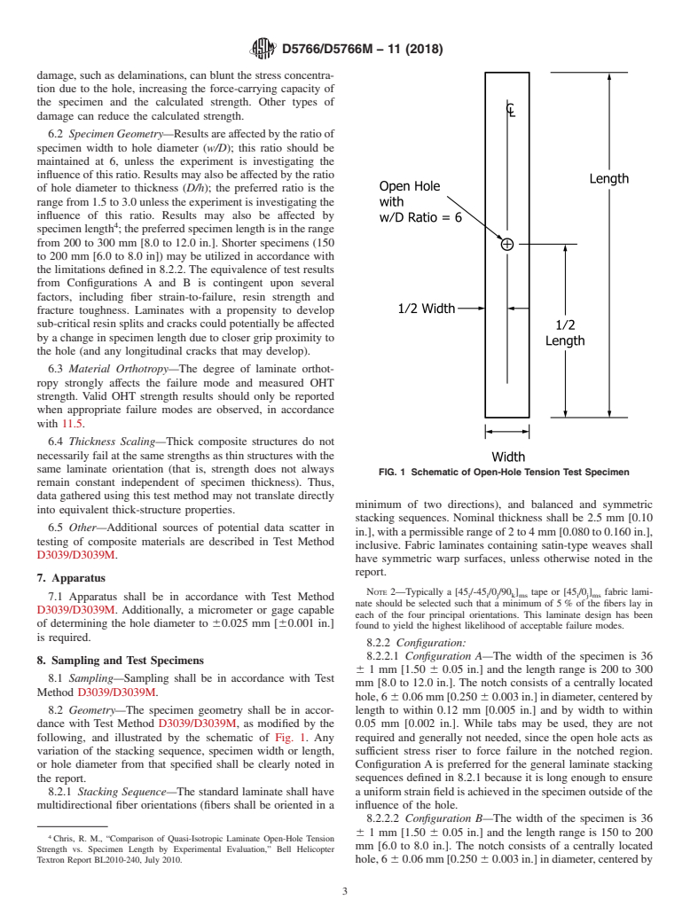
FIG. 1 Schematic of Open-Hole Tension Test Specimen
remain constant independent of specimen thickness). Thus,
data gathered using this test method may not translate directly
minimum of two directions), and balanced and symmetric
into equivalent thick-structure properties.
stacking sequences. Nominal thickness shall be 2.5 mm [0.10
6.5 Other—Additional sources of potential data scatter in
in.], with a permissible range of 2 to 4 mm [0.080 to 0.160 in.],
testing of composite materials are described in Test Method
inclusive. Fabric laminates containing satin-type weaves shall
D3039/D3039M.
have symmetric warp surfaces, unless otherwise noted in the
report.
7. Apparatus
NOTE 2—Typically a [45 /-45 /0 /90 ] tape or [45 /0 ] fabric lami-
i i j k ms i j ms
7.1 Apparatus shall be in accordance with Test Method
nate should be selected such that a minimum of 5 % of the fibers lay in
D3039/D3039M. Additionally, a micrometer or gage capable
each of the four principal orientations. This laminate design has been
of determining the hole diameter to 60.025 mm [60.001 in.]
found to yield the highest likelihood of acceptable failure modes.
is required.
8.2.2 Configuration:
8.2.2.1 Configuration A—The width of the specimen is 36
8. Sampling and Test Specimens
6 1 mm [1.50 6 0.05 in.] and the length range is 200 to 300
8.1 Sampling—Sampling shall be in accordance with Test
mm [8.0 to 12.0 in.]. The notch consists of a centrally located
Method D3039/D3039M.
hole, 6 6 0.06 mm [0.250 6 0.003 in.] in diameter, centered by
length to within 0.12 mm [0.005 in.] and by width to within
8.2 Geometry—The specimen geometry shall be in accor-
dance with Test Method D3039/D3039M, as modified by the 0.05 mm [0.002 in.]. While tabs may be used, they are not
following, and illustrated by the schematic of Fig. 1. Any required and generally not needed, since the open hole acts as
variation of the stacking sequence, specimen width or length, sufficient stress riser to force failure in the notched region.
or hole diameter from that specified shall be clearly noted in Configuration A is preferred for the general laminate stacking
the report. sequences defined in 8.2.1 because it is long enough to ensure
8.2.1 Stacking Sequence—The standard laminate shall have a uniform strain field is achieved in the
...
This document is not an ASTM standard and is intended only to provide the user of an ASTM standard an indication of what changes have been made to the previous version. Because
it may not be technically possible to adequately depict all changes accurately, ASTM recommends that users consult prior editions as appropriate. In all cases only the current version
of the standard as published by ASTM is to be considered the official document.
Designation: D5766/D5766M − 11 D5766/D5766M − 11 (Reapproved 2018)
Standard Test Method for
Open-Hole Tensile Strength of Polymer Matrix Composite
Laminates
This standard is issued under the fixed designation D5766/D5766M; the number immediately following the designation indicates the
year of original adoption or, in the case of revision, the year of last revision. A number in parentheses indicates the year of last
reapproval. A superscript epsilon (´) indicates an editorial change since the last revision or reapproval.
1. Scope
1.1 This test method determines the open-hole tensile strength of multidirectional polymer matrix composite laminates
reinforced by high-modulus fibers. The composite material forms are limited to continuous-fiber or discontinuous-fiber (tape or
fabric, or both) reinforced composites in which the laminate is balanced and symmetric with respect to the test direction. The range
of acceptable test laminates and thicknesses are described in 8.2.1.
1.2 The values stated in either SI units or inch-pound units are to be regarded separately as standard. The values stated in each
system may not be exact equivalents; therefore, each system shall be used independently of the other. Combining values from the
two systems may result in non-conformance with the standard.
1.2.1 Within the text the inch-pound units are shown in brackets.
1.3 This standard does not purport to address all of the safety concerns, if any, associated with its use. It is the responsibility
of the user of this standard to establish appropriate safety safety, health, and healthenvironmental practices and determine the
applicability of regulatory limitations prior to use.
1.4 This international standard was developed in accordance with internationally recognized principles on standardization
established in the Decision on Principles for the Development of International Standards, Guides and Recommendations issued
by the World Trade Organization Technical Barriers to Trade (TBT) Committee.
2. Referenced Documents
2.1 ASTM Standards:
D792 Test Methods for Density and Specific Gravity (Relative Density) of Plastics by Displacement
D883 Terminology Relating to Plastics
D2584 Test Method for Ignition Loss of Cured Reinforced Resins
D2734 Test Methods for Void Content of Reinforced Plastics
D3039/D3039M Test Method for Tensile Properties of Polymer Matrix Composite Materials
D3171 Test Methods for Constituent Content of Composite Materials
D3878 Terminology for Composite Materials
D5229/D5229M Test Method for Moisture Absorption Properties and Equilibrium Conditioning of Polymer Matrix Composite
Materials
E6 Terminology Relating to Methods of Mechanical Testing
E177 Practice for Use of the Terms Precision and Bias in ASTM Test Methods
E456 Terminology Relating to Quality and Statistics
E691 Practice for Conducting an Interlaboratory Study to Determine the Precision of a Test Method
E1309 Guide for Identification of Fiber-Reinforced Polymer-Matrix Composite Materials in Databases (Withdrawn 2015)
E1434 Guide for Recording Mechanical Test Data of Fiber-Reinforced Composite Materials in Databases (Withdrawn 2015)
3. Terminology
3.1 Definitions—Terminology D3878 defines terms relating to high-modulus fibers and their composites. Terminology D883
defines terms relating to plastics. Terminology E6 defines terms relating to mechanical testing. Terminology E456 and Practice
This test method is under the jurisdiction of ASTM Committee D30 on Composite Materials and is the direct responsibility of Subcommittee D30.05 on Structural Test
Methods.
Current edition approved Jan. 1, 2011June 1, 2018. Published February 2011July 2018. Originally approved in 1995. Last previous edition approved in 20072011 as
D5766/D5766M – 07.D5766/D5766M – 11. DOI: 10.1520/D5766_D5766M-11.10.1520/D5766_D5766M-11R18.
For referenced ASTM standards, visit the ASTM website, www.astm.org, or contact ASTM Customer Service at service@astm.org. For Annual Book of ASTM Standards
volume information, refer to the standard’s Document Summary page on the ASTM website.
The last approved version of this historical standard is referenced on www.astm.org.
Copyright © ASTM International, 100 Barr Harbor Drive, PO Box C700, West Conshohocken, PA 19428-2959. United States
D5766/D5766M − 11 (2018)
E177 define terms relating to statistics. In the event of a conflict between terms, Terminology D3878 shall have precedence over
the other standards.
3.2 Definitions of Terms Specific to This Standard:
NOTE 1—If the term represents a physical quantity, its analytical dimensions are stated immediately following the term (or letter symbol) in
fundamental dimension form, using the following ASTM standard symbology for fundamental dimensions, shown within square brackets: [M] for mass,
[L] for length, [T] for time, [θ] for thermodynamic temperature, and [nd] for non-dimensional quantities. Use of these symbols is restricted to analytical
dimensions when used with square brackets, as the symbols may have other definitions when used without the brackets.
3.2.1 diameter-to-thickness ratio, D/h [nd], n—in an open-hole specimen, the ratio of the hole diameter to the specimen
thickness.
3.2.1.1 Discussion—The diameter-to-thickness ratio may be either a nominal value determined from nominal dimensions or an
actual value determined from measured dimensions.
3.2.2 nominal value, n—a value, existing in name only, assigned to a measurable property for the purpose of convenient
designation. Tolerances may be applied to a nominal value to define an acceptable range for the property.
3.2.3 principal material coordinate system, n—a coordinate system with axes that are normal to the planes of symmetry inherent
to a material.
3.2.3.1 Discussion—Common usage, at least for Cartesian axes (123, xyz, and so forth), generally assigns the coordinate system
axes to the normal directions of planes of symmetry in order that the highest property value in a normal direction (for elastic
properties, the axis of greatest stiffness) would be 1 or x, and the lowest (if applicable) would be 3 or z. Anisotropic materials do
not have a principal material coordinate system due to the total lack of symmetry, while, for isotropic materials, any coordinate
system is a principal material coordinate system. In laminated composites, the principal material coordinate system has meaning
only with respect to an individual orthotropic lamina. The related term for laminated composites is “reference coordinate system.”
3.2.4 reference coordinate system, n—a coordinate system for laminated composites used to define ply orientations. One of the
reference coordinate system axes (normally the Cartesian x-axis) is designated the reference axis, assigned a position, and the ply
principal axis of each ply in the laminate is referenced relative to the reference axis to define the ply orientation for that ply.
3.2.5 specially orthotropic, adj—a description of an orthotropic material as viewed in its principal material coordinate system.
In laminated composites, a specially orthotropic laminate is a balanced and symmetric laminate of the [0 /90 ] family as viewed
i j ns
from the reference coordinate system, such that the membrane-bending coupling terms of the laminate constitutive relation are
zero.
3.2.6 width-to-diameter ratio, w/D [nd], n—in an open-hole specimen, the ratio of the specimen width to the hole diameter.
3.2.6.1 Discussion—The width-to-diameter ratio may be either a nominal value determined from nominal dimensions or an
actual value determined from measured dimensions.
3.3 Symbols:
A = cross-sectional area of a specimen
CV = coefficient of variation statistic of a sample population for a given property (in percent)
D = hole diameter
h = specimen thickness
n = number of specimens per sample population
N = number of plies in laminate under test
OHTu
F = ultimate open-hole (notched) tensile strength in the test direction
x
max
P = maximum force carried by test specimen prior to failure
s = standard deviation statistic of a sample population for a given property
n-1
S = repeatability (within laboratory precision) standard deviation, calculated in accordance with Practice E691
r
S = reproducibility (between laboratory precision) standard deviation, calculated in accordance with Practice E691
R
w = specimen width
x = test result for an individual specimen from the sample population for a given property
i
x¯5x¯5 mean or average (estimate of mean) of a sample population for a given property
σ = normal stress
4. Summary of Test Method
4.1 A uniaxial tension test of a balanced, symmetric laminate is performed in accordance with Test Method D3039/D3039M,
although with a centrally located hole. Edge-mounted extensometer displacement transducers are optional. Ultimate strength is
calculated based on the gross cross-sectional area, disregarding the presence of the hole. While the hole causes a stress
concentration and reduced net section, it is common aerospace practice to develop notched design allowable strengths based on
gross section stress to account for various stress concentrations (fastener holes, free edges, flaws, damage, and so forth) not
explicitly modeled in the stress analysis.
4.2 The only acceptable failure mode for ultimate open-hole tensile strength is one which passes through the hole in the test
specimen.
D5766/D5766M − 11 (2018)
5. Significance and Use
5.1 This test method is designed to produce notched tensile strength data for structural design allowables, material
specifications, research and development, and quality assurance. Factors that influence the notched tensile strength and should
therefore be reported include the following: material, methods of material fabrication, accuracy of lay-up, laminate stacking
sequence and overall thickness, specimen geometry (including hole diameter, diameter-to-thickness ratio, and width-to-diameter
ratio), specimen preparation (especially of the hole), specimen conditioning, environment of testing, specimen alignment and
gripping, speed of testing, time at temperature, void content, and volume percent reinforcement. Properties that may be derived
from this test method include the following:
5.1.1 Open-hole (notched) tensile strength (OHT).
6. Interferences
6.1 Hole Preparation—Due to the dominating presence of the notch, and the lack of need to measure the material response,
results from this test method are relatively insensitive to parameters that would be of concern in an unnotched tensile property test.
However, since the notch dominates the strength, consistent preparation of the hole, without damage to the laminate, is important
to meaningful results. Damage due to hole preparation will affect strength results. Some types of damage, such as delaminations,
can blunt the stress concentration due to the hole, increasing the force-carrying capacity of the specimen and the calculated
strength. Other types of damage can reduce the calculated strength.
6.2 Specimen Geometry—Results are affected by the ratio of specimen width to hole diameter (w/D); this ratio should be
maintained at 6, unless the experiment is investigating the influence of this ratio. Results may also be affected by the ratio of hole
diameter to thickness (D/h); the preferred ratio is the range from 1.5 to 3.0 unless the experiment is investigating the influence of
this ratio. Results may also be affected by specimen length ; the preferred specimen length is in the range from 200 to 300 mm
[8.0 to 12.0 in.]. Shorter specimens (150 to 200 mm [6.0 to 8.0 in]) may be utilized in accordance with the limitations defined in
8.2.2. The equivalence of test results from Configurations A and B is contingent upon several factors, including fiber
strain-to-failure, resin strength and fracture toughness. Laminates with a propensity to develop sub-critical resin splits and cracks
could potentially be affected by a change in specimen length due to closer grip proximity to the hole (and any longitudinal cracks
that may develop).
6.3 Material Orthotropy—The degree of laminate orthotropy strongly affects the failure mode and measured OHT strength.
Valid OHT strength results should only be reported when appropriate failure modes are observed, in accordance with 11.5.
6.4 Thickness Scaling—Thick composite structures do not necessarily fail at the same strengths as thin structures with the same
laminate orientation (that is, strength does not always remain constant independent of specimen thickness). Thus, data gathered
using this test method may not translate directly into equivalent thick-structure properties.
6.5 Other—Additional sources of potential data scatter in testing of composite materials are described in Test Method
D3039/D3039M.
7. Apparatus
7.1 Apparatus shall be in accordance with Test Method D3039/D3039M. Additionally, a micrometer or gage capable of
determining the hole diameter to 60.025 mm [60.001 in.] is required.
8. Sampling and Test Specimens
8.1 Sampling—Sampling shall be in accordance with Test Method D3039/D3039M.
8.2 Geometry—The specimen geometry shall be in accordance with Test Method D3039/D3039M, as modified by the following,
and illustrated by the schematic of Fig. 1. Any variation of the stacking sequence, specimen width or length, or hole diameter from
that specified shall be clearly noted in the report.
8.2.1 Stacking Sequence—The standard laminate shall have multidirectional fiber orientations (fibers shall be oriented in a
minimum of two directions), and balanced and symmetric stacking sequences. Nominal thickness shall be 2.5 mm [0.10 in.], with
a permissible range of 2 to 4 mm [0.080 to 0.160 in.], inclusive. Fabric laminates containing satin-type weaves shall have
symmetric warp surfaces, unless otherwise noted in the report.
NOTE 2—Typically a [45 /-45 /0 /90 ] tape or [45 /0 ] fabric laminate should be selected such that a minimum of 5 % of the fibers lay in each of
i i j k ms i j ms
the four principal orientations. This laminate design has been found to yield the highest likelihood of acceptable failure modes.
8.2.2 Configuration:
8.2.2.1 Configuration A—The width of the specimen is 36 6 1 mm [1.50 6 0.05 in.] and the length range is 200 to 300 mm
[8.0 to 12.0 in.]. The notch consists of a centrally located hole, 6 6 0.06 mm [0.250 6 0.003 in.] in diameter, centered by length
Chris, R. M., “Comparison of Quasi-Isotropic Laminate Open-Hole Tension Strength vs. Specimen
...
Questions, Comments and Discussion
Ask us and Technical Secretary will try to provide an answer. You can facilitate discussion about the standard in here.