


ASTM E637-05(2016)
(Test Method)Standard Test Method for Calculation of Stagnation Enthalpy from Heat Transfer Theory and Experimental Measurements of Stagnation-Point Heat Transfer and Pressure
Standard Test Method for Calculation of Stagnation Enthalpy from Heat Transfer Theory and Experimental Measurements of Stagnation-Point Heat Transfer and Pressure
SIGNIFICANCE AND USE
3.1 The purpose of this test method is to provide a standard calculation of the stagnation enthalpy of an aerodynamic simulation device using the heat transfer theory and measured values of stagnation point heat transfer and pressure. A stagnation enthalpy obtained by this test method gives a consistent set of data, along with heat transfer and stagnation pressure for ablation computations.
SCOPE
1.1 This test method covers the calculation from heat transfer theory of the stagnation enthalpy from experimental measurements of the stagnation-point heat transfer and stagnation pressure.
1.2 Advantages:
1.2.1 A value of stagnation enthalpy can be obtained at the location in the stream where the model is tested. This value gives a consistent set of data, along with heat transfer and stagnation pressure, for ablation computations.
1.2.2 This computation of stagnation enthalpy does not require the measurement of any arc heater parameters.
1.3 Limitations and Considerations—There are many factors that may contribute to an error using this type of approach to calculate stagnation enthalpy, including:
1.3.1 Turbulence—The turbulence generated by adding energy to the stream may cause deviation from the laminar equilibrium heat transfer theory.
1.3.2 Equilibrium, Nonequilibrium, or Frozen State of Gas—The reaction rates and expansions may be such that the gas is far from thermodynamic equilibrium.
1.3.3 Noncatalytic Effects—The surface recombination rates and the characteristics of the metallic calorimeter may give a heat transfer deviation from the equilibrium theory.
1.3.4 Free Electric Currents—The arc-heated gas stream may have free electric currents that will contribute to measured experimental heat transfer rates.
1.3.5 Nonuniform Pressure Profile—A nonuniform pressure profile in the region of the stream at the point of the heat transfer measurement could distort the stagnation point velocity gradient.
1.3.6 Mach Number Effects—The nondimensional stagnation-point velocity gradient is a function of the Mach number. In addition, the Mach number is a function of enthalpy and pressure such that an iterative process is necessary.
1.3.7 Model Shape—The nondimensional stagnation-point velocity gradient is a function of model shape.
1.3.8 Radiation Effects—The hot gas stream may contribute a radiative component to the heat transfer rate.
1.3.9 Heat Transfer Rate Measurement—An error may be made in the heat transfer measurement (see Method E469 and Test Methods E422, E457, E459, and E511).
1.3.10 Contamination—The electrode material may be of a large enough percentage of the mass flow rate to contribute to the heat transfer rate measurement.
1.4 The values stated in SI units are to be regarded as standard. No other units of measurement are included in this standard.
1.4.1 Exception—The values given in parentheses are for information only.
1.5 This standard does not purport to address all of the safety concerns, if any, associated with its use. It is the responsibility of the user of this standard to establish appropriate safety and health practices and determine the applicability of regulatory limitations prior to use.
General Information
Buy Standard
Standards Content (Sample)
NOTICE: This standard has either been superseded and replaced by a new version or withdrawn.
Contact ASTM International (www.astm.org) for the latest information
Designation: E637 − 05 (Reapproved 2016)
Standard Test Method for
Calculation of Stagnation Enthalpy from Heat Transfer
Theory and Experimental Measurements of Stagnation-Point
Heat Transfer and Pressure
This standard is issued under the fixed designation E637; the number immediately following the designation indicates the year of
original adoption or, in the case of revision, the year of last revision.Anumber in parentheses indicates the year of last reapproval.A
superscript epsilon (´) indicates an editorial change since the last revision or reapproval.
INTRODUCTION
The enthalpy (energy per unit mass) determination in a hot gas aerodynamic simulation device is
a difficult measurement. Even at temperatures that can be measured with thermocouples, there are
many corrections to be made at 600 K and above. Methods that are used for temperatures above the
range of thermocouples that give bulk or average enthalpy values are energy balance (see Practice
E341), sonic flow (1, 2), and the pressure rise method (3). Local enthalpy values (thus distribution)
may be obtained by using either an energy balance probe (see Method E470), or the spectrometric
technique described in Ref (4).
1. Scope 1.3.3 Noncatalytic Effects—Thesurfacerecombinationrates
and the characteristics of the metallic calorimeter may give a
1.1 This test method covers the calculation from heat
heat transfer deviation from the equilibrium theory.
transfer theory of the stagnation enthalpy from experimental
1.3.4 Free Electric Currents—The arc-heated gas stream
measurements of the stagnation-point heat transfer and stagna-
mayhavefreeelectriccurrentsthatwillcontributetomeasured
tion pressure.
experimental heat transfer rates.
1.2 Advantages:
1.3.5 Nonuniform Pressure Profile—Anonuniform pressure
1.2.1 Avalue of stagnation enthalpy can be obtained at the profile in the region of the stream at the point of the heat
location in the stream where the model is tested. This value transfer measurement could distort the stagnation point veloc-
gives a consistent set of data, along with heat transfer and ity gradient.
stagnation pressure, for ablation computations. 1.3.6 Mach Number Effects—The nondimensional
stagnation-point velocity gradient is a function of the Mach
1.2.2 This computation of stagnation enthalpy does not
number.Inaddition,theMachnumberisafunctionofenthalpy
require the measurement of any arc heater parameters.
and pressure such that an iterative process is necessary.
1.3 Limitations and Considerations—There are many fac-
1.3.7 Model Shape—The nondimensional stagnation-point
tors that may contribute to an error using this type of approach
velocity gradient is a function of model shape.
to calculate stagnation enthalpy, including:
1.3.8 Radiation Effects—The hot gas stream may contribute
1.3.1 Turbulence—The turbulence generated by adding en-
a radiative component to the heat transfer rate.
ergy to the stream may cause deviation from the laminar
1.3.9 Heat Transfer Rate Measurement—An error may be
equilibrium heat transfer theory.
made in the heat transfer measurement (see Method E469 and
1.3.2 Equilibrium, Nonequilibrium, or Frozen State of
Test Methods E422, E457, E459, and E511).
Gas—The reaction rates and expansions may be such that the
1.3.10 Contamination—The electrode material may be of a
gas is far from thermodynamic equilibrium.
large enough percentage of the mass flow rate to contribute to
the heat transfer rate measurement.
1.4 The values stated in SI units are to be regarded as
This test method is under the jurisdiction of ASTM Committee E21 on Space
standard. No other units of measurement are included in this
Simulation andApplications of SpaceTechnology and is the direct responsibility of
standard.
Subcommittee E21.08 on Thermal Protection.
1.4.1 Exception—The values given in parentheses are for
Current edition approved April 1, 2016. Published April 2016. Originally
approved in 1978. Last previous edition approved in 2011 as E637–05(2011).
information only.
DOI: 10.1520/E0637-05R16.
1.5 This standard does not purport to address all of the
The boldface numbers in parentheses refer to the list of references appended to
this method. safety concerns, if any, associated with its use. It is the
Copyright © ASTM International, 100 Barr Harbor Drive, PO Box C700, West Conshohocken, PA 19428-2959. United States
E637 − 05 (2016)
TABLE 1 Heat Transfer and Enthalpy Computation Constants for
responsibility of the user of this standard to establish appro-
Various Gases
priate safety and health practices and determine the applica-
1/2 1/2 1/2 1/2
K , kg/(N ·m ·s) K ,(N ·m ·s)/kg
bility of regulatory limitations prior to use. i M
Gas
3/2 1/2 3/2 1/2
(lb/(ft ·s·atm )) ((ft ·s·atm )/lb)
−4
Air 3.905 × 10 (0.0461) 2561 (21.69)
2. Referenced Documents
−4
Argon 5.513 × 10 (0.0651) 1814 (15.36)
−4
2.1 ASTM Standards: Carbon dioxide 4.337 × 10 (0.0512) 2306 (19.53)
−4
Hydrogen 1.287 × 10 (0.0152) 7768 (65.78)
E341Practice for Measuring Plasma Arc Gas Enthalpy by
−4
Nitrogen 3.650 × 10 (0.0431) 2740 (23.20)
Energy Balance
E422Test Method for Measuring Heat Flux Using a Water-
Cooled Calorimeter
flow theory which becomes inaccurate for M <2. An im-
E457Test Method for Measuring Heat-Transfer Rate Using
oo
proved Mach number dependence at lower Mach numbers can
a Thermal Capacitance (Slug) Calorimeter
beobtainedbyremovingthe“modified”Newtonianexpression
E459Test Method for Measuring Heat Transfer Rate Using
andreplacingitwithamoreappropriateexpressionasfollows:
a Thin-Skin Calorimeter
E469Measuring Heat Flux Using a Multiple-Wafer Calo- 0.5
β D/U
~ !
K q˙ oo
Eq 3
M
rimeter (Withdrawn 1982) H 2 H 5 F G (2)
0.5
e w
P /R β D/U
~ !
~ !
t oo x50
E470Measuring Gas Enthalpy Using Calorimeter Probes
(Withdrawn 1982) Where the “modified” Newtonian stagnation-point velocity
E511TestMethodforMeasuringHeatFluxUsingaCopper- gradient is given by:
Constantan Circular Foil, Heat-Flux Transducer 2 0.5
4 γ 2 1 M 12
@~ ! #
oo
~β D/U ! 5 (3)
F G
oo 2
x50
γ M
oo
3. Significance and Use
A potential problem exists when using Eq 3 to remove the
3.1 The purpose of this test method is to provide a standard
“modified” Newtonian velocity gradient because of the singu-
calculation of the stagnation enthalpy of an aerodynamic
larity at M =0. The procedure recommended here should be
oo
simulation device using the heat transfer theory and measured
limited to M > 0.1
oo
values of stagnation point heat transfer and pressure. A
stagnation enthalpy obtained by this test method gives a
where:
consistent set of data, along with heat transfer and stagnation
−1
β = stagnation-point velocity gradient, s ,
pressure for ablation computations.
D = hemispherical diameter, m (or ft),
U = freestream velocity, m/s (or ft/s),
∞
4. Enthalpy Computations
(βD/U ) = dimensionless stagnation velocity gradient,
∞ x=0
4.1 This method of calculating the stagnation enthalpy is
K = enthalpy computation constant,
M
1/2 1/2 3/2 1/2
based on experimentally measured values of the stagnation-
(N ·m · s)/kg or (ft ·atm ·s)/lb, and
pointheattransferrateandpressuredistributionandtheoretical M∞ = the freestream Mach number.
calculation of laminar equilibrium catalytic stagnation-point
For subsonic Mach numbers, an expression for (βD/U )
∞ x=0
heat transfer on a hemispherical body. The equilibrium cata-
for a hemisphere is given in Ref (6) as follows:
lytic theoretical laminar stagnation-point heat transfer rate for
βD
a hemispherical body is as follows (5): 2
5 3 2 0.755 M M ,1 (4)
S D ~ !
x50 ` `
U
`
R
For a Mach number of 1 or greater, (βD/U ) for a
q 5 K ~H 2 H ! (1)
Œ
i e w ∞ x=0
P
t
hemisphere based on “classical” Newtonian flow theory is
presented in Ref (7) as follows:
where:
2 2
1 0.5
q = stagnation-pointheattransferrate,W/m (orBtu/ft ·s),
γ 2 1 γ21
P = model stagnation pressure, Pa (or atm), 11
t
8 γ 2 1 M 2 12 2
βD @~ ! #
`
R = hemispherical nose radius, m (or ft),
S D
x50
~γ 2 1!M 2 12
U ~γ11!M 2 @ #
`
` `
H = stagnation enthalpy, J/kg (or Btu/lb),
5 6
3 4
e
2γM 2 2 ~γ 2 1!
H = wall enthalpy, J/kg (or Btu/lb), and `
w
K = heat transfer computation constant.
(5)
i
4.2 Low Mach Number Correction—Eq 1 is simple and
Avariationof(βD/U ) with M andγisshowninFig.1.
∞ x=0 ∞
convenient to use since K can be considered approximately
i The value of the Newtonian dimensionless velocity gradient
constant(seeTable1).However,Eq1isbasedonastagnation-
approaches a constant value as the Mach number approaches
point velocity gradient derived using “modified” Newtonian
infinity:
βD γ 2 1
For referenced ASTM standards, visit the ASTM website, www.astm.org, or 5 4 (6)
S D ΠS D
x50,M→`
U γ
`
contact ASTM Customer Service at service@astm.org. For Annual Book of ASTM
Standards volume information, refer to the standard’s Document Summary page on
and thus, sinceγ, the ratio of specific heats, is a function of
the ASTM website.
enthalpy, (βD/U ) is also a function of enthalpy.Again, an
The last approved version of this historical standard is referenced on ∞ x=0
www.astm.org. iteration is necessary. From Fig. 1, it can be seen that
E637 − 05 (2016)
FIG. 1 Dimensionless Velocity Gradient as a Function of Mach Number and Ratio of Specific Heats
(βD/U ) for a hemisphere is approximately 1 for large to the area of the nozzle throat, A/A'.Fig. 2(a) and Fig. 2(b) are
∞ x=0
Mach numbers and γ=1.2. K is tabulated in Table 1 using reproduced from Ref (8) for the reader’s convenience in
M
(βD/U ) =1 and K from Ref (5).
determining Mach numbers for supersonic flows.
∞ x=0 i
4.3.2 The subsonic Mach number may be determined from
4.3 Mach Number Determination:
4.3.1 TheMachnumberofastreamisafunctionofthetotal Fig.3(seealsoTestMethodE511).Aniterationisnecessaryto
determine the Mach number since the ratio of specific heats,γ,
enthalpy, the ratio of freestream pressure to the total pressure,
p/p ,thetotalpressure, p ,andtheratiooftheexitnozzlearea is also a function of enthalpy and pressure.
t t
1 1
FIG. 2 (a) Variation of Area Ratio with Mach Numbers
E637 − 05 (2016)
FIG. 2 (b) Variation of Area Ratio with Mach Numbers (continued)
FIG. 3 Subsonic Pressure Ratio as a Function of Mach Number and γ
E637 − 05 (2016)
FIG. 4 Isentropic Exponent for Air in Equilibrium
4.3.3 Theratioofspecificheats,γ,isshownasafunctionof 4.6.2 The proper application requires some knowledge of
entropy and enthalpy for air in Fig. 4 from Ref (9). S/R is the
the radiant environment in the stream at the desired operating
dimensionless entropy, and H/RT is the dimensionless en-
conditions. Usually, it is necessary to measure the radiant heat
thalpy.
transfer rate either directly or indirectly.The following is a list
of suggested methods by which the necessary measurements
4.4 Velocity Gradient Calculation from Pressure
can be made.
Distribution—The dimensionless stagnation-point velocity
gradient may be obtained from an experimentally measured 4.6.2.1 Direct Measurement with Radiometer—Radiometers
pressure distribution by using Bernoulli’s compressible flow
are available for the measurement of the incident radiant flux
equation as follows:
while excluding the convective heat transfer. In its simplest
γ21 0.5
form, the radiometer is a slug, thin-skin, or circular foil
@1 2 p/p γ #
U ~ !
t
5 (7) calorimeter with a sensing area with a coating of known
S D
γ21 0.5
U
`
1 2 p /p γ
@ ~ ! #
` t
2 absorptance and covered with some form of window. The
purpose of the window is to prevent convective heat transfer
where the velocity ratio may be calculated along the body
from affecting the calorimeter while transmitting the radiant
from the stagnation point. Thus, the dimensionless stagnation-
energy.Thewindowisusuallymadeofquartzorsapphire.The
point velocity gradient, (βD/U ) , is the slope of the U/U
∞ x=0 ∞
sensing surface is at the stagnation point of a test probe and is
and the x/D curve at the stagnation point.
located in such a manner that the view angle is not restricted.
4.5 Model Shape—Thenondimensionalstagnation-pointve-
The basic radiometer view angle should be 120° or greater.
locity gradient is a function of the model shape and the Mach
This technique allows for immersion of the radiometer in the
number. For supersonic Mach numbers, the heat transfer
test stream and direct measurement of the radiant heat transfer
relationship between a hemisphere and other axisymmetric
rate. There is a major limitation to this technique, however, in
blunt bodies is shown in Fig. 5 (10).In Fig. 5, r is the corner
c
that even with high-pressure water cooling of the radiometer
radius, r isthebodyradius, r isthenoseradius,and q˙ isthe
b n s,h
enclosure, the window is poorly cooled and thus the use of
stagnation-point heat transfer rate on a hemisphere. For sub-
windows is limited to relatively low convective heat transfer
sonic Mach numbers, the same type of variation is shown in
conditions or very short exposure times, or both.Also, stream
Fig. 6(6).
contaminants coat the window and reduce its transmittance.
4.6 Radiation Effects:
4.6.2.2 Direct Measurement with Radiometer Mounted in
4.6.1 As this test method depends on the accurate determi-
Cavity—Thetwolimitationsnotedin4.6.2.1maybeovercome
nation of the convective stagnation-point heat transfer, any
by mounting the radiometer at the bottom of a cavity open to
radiant energy absorbed by the calorimeter surface and incor-
the stagnation point of the test probe (see Fig. 7). Good results
rectly attributed to the convective mode will directly affect the
can be obtained by using a simple calorimeter in place of the
overall accuracy of the test method. Generally, the sources of
radiometer with a material of known absorptance. When using
radiant energy are the hot gas stream itself or the gas heating
this configuration, the measured radiant heat transfer rate is
device, or both. For instance, arc heaters operated at high
pressure (10 atm or higher) can produce significant radiant used in the following equation to determine the stagnation-
point radiant heat transfer, assuming diffuse radiation:
fluxes at the nozzle exit plane.
E637 − 05 (2016)
FIG. 5 Stagnation-Point Heating-Rate Parameters on Hemispherical Segments of Different Curvatures for Varying Corner-Radius Ratios
E637 − 05 (2016)
FIG. 6 Stagnation-Point Heat Transfer Ratio to a Blunt Body and a Hemisphere as a Function of the
Body-to-Nose Radius in a Subsonic Stream
FIG. 7 Test Probe
2 2 2 1/2
1 F 51/2 X 2 X 2 4E D (9)
@ ~ ! #
q˙ 5 q˙ (8)
r r
1 2
α F
2 12
where:
q˙ = radiant tra
...
This document is not an ASTM standard and is intended only to provide the user of an ASTM standard an indication of what changes have been made to the previous version. Because
it may not be technically possible to adequately depict all changes accurately, ASTM recommends that users consult prior editions as appropriate. In all cases only the current version
of the standard as published by ASTM is to be considered the official document.
Designation: E637 − 05 (Reapproved 2011) E637 − 05 (Reapproved 2016)
Standard Test Method for
Calculation of Stagnation Enthalpy from Heat Transfer
Theory and Experimental Measurements of Stagnation-Point
Heat Transfer and Pressure
This standard is issued under the fixed designation E637; the number immediately following the designation indicates the year of
original adoption or, in the case of revision, the year of last revision. A number in parentheses indicates the year of last reapproval. A
superscript epsilon (´) indicates an editorial change since the last revision or reapproval.
INTRODUCTION
The enthalpy (energy per unit mass) determination in a hot gas aerodynamic simulation device is
a difficult measurement. Even at temperatures that can be measured with thermocouples, there are
many corrections to be made at 600 K and above. Methods that are used for temperatures above the
range of thermocouples that give bulk or average enthalpy values are energy balance (see Practice
E341), sonic flow (1, 2), and the pressure rise method (3). Local enthalpy values (thus distribution)
may be obtained by using either an energy balance probe (see Method E470), or the spectrometric
technique described in Ref (4).
1. Scope
1.1 This test method covers the calculation from heat transfer theory of the stagnation enthalpy from experimental
measurements of the stagnation-point heat transfer and stagnation pressure.
1.2 Advantages:
1.2.1 A value of stagnation enthalpy can be obtained at the location in the stream where the model is tested. This value gives
a consistent set of data, along with heat transfer and stagnation pressure, for ablation computations.
1.2.2 This computation of stagnation enthalpy does not require the measurement of any arc heater parameters.
1.3 Limitations and Considerations—There are many factors that may contribute to an error using this type of approach to
calculate stagnation enthalpy, including:
1.3.1 Turbulence—The turbulence generated by adding energy to the stream may cause deviation from the laminar equilibrium
heat transfer theory.
1.3.2 Equilibrium, Nonequilibrium, or Frozen State of Gas—The reaction rates and expansions may be such that the gas is far
from thermodynamic equilibrium.
1.3.3 Noncatalytic Effects—The surface recombination rates and the characteristics of the metallic calorimeter may give a heat
transfer deviation from the equilibrium theory.
1.3.4 Free Electric Currents—The arc-heated gas stream may have free electric currents that will contribute to measured
experimental heat transfer rates.
1.3.5 Nonuniform Pressure Profile—A nonuniform pressure profile in the region of the stream at the point of the heat transfer
measurement could distort the stagnation point velocity gradient.
1.3.6 Mach Number Effects—The nondimensional stagnation-point velocity gradient is a function of the Mach number. In
addition, the Mach number is a function of enthalpy and pressure such that an iterative process is necessary.
1.3.7 Model Shape—The nondimensional stagnation-point velocity gradient is a function of model shape.
1.3.8 Radiation Effects—The hot gas stream may contribute a radiative component to the heat transfer rate.
1.3.9 Heat Transfer Rate Measurement—An error may be made in the heat transfer measurement (see Method E469 and Test
Methods E422, E457, E459, and E511).
This test method is under the jurisdiction of ASTM Committee E21 on Space Simulation and Applications of Space Technology and is the direct responsibility of
Subcommittee E21.08 on Thermal Protection.
Current edition approved Oct. 1, 2011April 1, 2016. Published April 2012April 2016. Originally approved in 1978. Last previous edition approved in 20052011 as
E637 – 05.E637 – 05 (2011). DOI: 10.1520/E0637-05R11.10.1520/E0637-05R16.
The boldface numbers in parentheses refer to the list of references appended to this method.
Copyright © ASTM International, 100 Barr Harbor Drive, PO Box C700, West Conshohocken, PA 19428-2959. United States
E637 − 05 (2016)
1.3.10 Contamination—The electrode material may be of a large enough percentage of the mass flow rate to contribute to the
heat transfer rate measurement.
1.4 The values stated in SI units are to be regarded as standard. No other units of measurement are included in this standard.
1.4.1 Exception—The values given in parentheses are for information only.
1.5 This standard does not purport to address all of the safety concerns, if any, associated with its use. It is the responsibility
of the user of this standard to establish appropriate safety and health practices and determine the applicability of regulatory
limitations prior to use.
2. Referenced Documents
2.1 ASTM Standards:
E341 Practice for Measuring Plasma Arc Gas Enthalpy by Energy Balance
E422 Test Method for Measuring Heat Flux Using a Water-Cooled Calorimeter
E457 Test Method for Measuring Heat-Transfer Rate Using a Thermal Capacitance (Slug) Calorimeter
E459 Test Method for Measuring Heat Transfer Rate Using a Thin-Skin Calorimeter
E469 Measuring Heat Flux Using a Multiple-Wafer Calorimeter (Withdrawn 1982)
E470 Measuring Gas Enthalpy Using Calorimeter Probes (Withdrawn 1982)
E511 Test Method for Measuring Heat Flux Using a Copper-Constantan Circular Foil, Heat-Flux Transducer
3. Significance and Use
3.1 The purpose of this test method is to provide a standard calculation of the stagnation enthalpy of an aerodynamic simulation
device using the heat transfer theory and measured values of stagnation point heat transfer and pressure. A stagnation enthalpy
obtained by this test method gives a consistent set of data, along with heat transfer and stagnation pressure for ablation
computations.
4. Enthalpy Computations
4.1 This method of calculating the stagnation enthalpy is based on experimentally measured values of the stagnation-point heat
transfer rate and pressure distribution and theoretical calculation of laminar equilibrium catalytic stagnation-point heat transfer on
a hemispherical body. The equilibrium catalytic theoretical laminar stagnation-point heat transfer rate for a hemispherical body is
as follows (5):
R
q 5 K ~H 2 H ! (1)
Œ
i e w
P
t
where:
2 2
q = stagnation-point heat transfer rate, W/m (or Btu/ft ·s),
P = model stagnation pressure, Pa (or atm),
t
R = hemispherical nose radius, m (or ft),
H = stagnation enthalpy, J/kg (or Btu/lb),
e
H = wall enthalpy, J/kg (or Btu/lb), and
w
K = heat transfer computation constant.
i
4.2 Low Mach Number Correction—Eq 1 is simple and convenient to use since K can be considered approximately constant
i
(see Table 1). However, Eq 1 is based on a stagnation-point velocity gradient derived using “modified” Newtonian flow theory
which becomes inaccurate for M <2. An improved Mach number dependence at lower Mach numbers can be obtained by
oo
removing the “modified” Newtonian expression and replacing it with a more appropriate expression as follows:
For referenced ASTM standards, visit the ASTM website, www.astm.org, or contact ASTM Customer Service at service@astm.org. For Annual Book of ASTM Standards
volume information, refer to the standard’s Document Summary page on the ASTM website.
The last approved version of this historical standard is referenced on www.astm.org.
TABLE 1 Heat Transfer and Enthalpy Computation Constants for
Various Gases
1/2 1/2 1/2 1/2
K , kg/(N ·m ·s) K , (N ·m ·s)/kg
i M
Gas
3/2 1/2 3/2 1/2
(lb/(ft ·s·atm )) ((ft ·s·atm )/lb)
−4
Air 3.905 × 10 (0.0461) 2561 (21.69)
−4
Argon 5.513 × 10 (0.0651) 1814 (15.36)
−4
Carbon dioxide 4.337 × 10 (0.0512) 2306 (19.53)
−4
Hydrogen 1.287 × 10 (0.0152) 7768 (65.78)
−4
Nitrogen 3.650 × 10 (0.0431) 2740 (23.20)
E637 − 05 (2016)
0.5
β D/U
~ !
K q˙ oo
Eq 3
M
H 2 H 5 F G (2)
0.5
e w
P /R β D/U
~ !
~ !
t oo x50
Where the “modified” Newtonian stagnation-point velocity gradient is given by:
2 0.5
4 @~γ2 1! M 12#
oo
β D/U 5 (3)
~ ! F G
oo x50
γ M
oo
A potential problem exists when using Eq 3 to remove the “modified” Newtonian velocity gradient because of the singularity
at M = 0. The procedure recommended here should be limited to M > 0.1
oo oo
where:
−1
β = stagnation-point velocity gradient, s ,
D = hemispherical diameter, m (or ft),
U = freestream velocity, m/s (or ft/s),
∞
(βD/U ) = dimensionless stagnation velocity gradient,
∞ x = 0
K = enthalpy computation constant,
M
1/2 1/2 3/2 1/2
(N ·m · s)/kg or (ft ·atm ·s)/lb, and
M∞ = the freestream Mach number.
For subsonic Mach numbers, an expression for (βD/U ) for a hemisphere is given in Ref (6) as follows:
∞ x = 0
βD
5 32 0.755 M M ,1 (4)
~ !
S D
x50 ` `
U
`
For a Mach number of 1 or greater, (βD/U ) for a hemisphere based on “classical” Newtonian flow theory is presented in
∞ x= 0
Ref (7) as follows:
1 0.5
γ2 1 γ21
8 ~γ2 1!M 2 12
βD @ #
`
5 (5)
S D
x50
γ2 1 M 2 12
U γ11 M 2 ~ !
~ ! @ #
`
` `
5 3 4 6
2γM 2 2 γ2 1
~ !
`
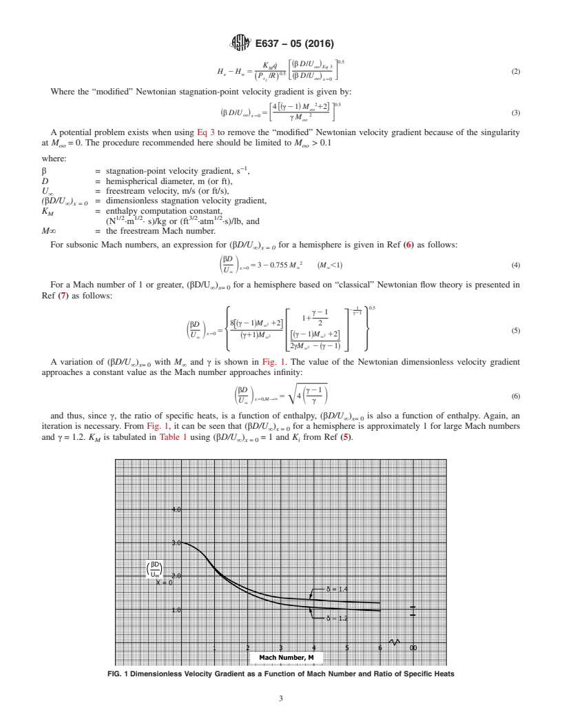
A variation of (βD/U ) with M and γ is shown in Fig. 1. The value of the Newtonian dimensionless velocity gradient
∞ x= 0 ∞
approaches a constant value as the Mach number approaches infinity:
βD γ2 1
5Œ4 (6)
S D S D
x50,M→`
U γ
`
and thus, since γ, the ratio of specific heats, is a function of enthalpy, (βD/U ) is also a function of enthalpy. Again, an
∞ x= 0
iteration is necessary. From Fig. 1, it can be seen that (βD/U ) for a hemisphere is approximately 1 for large Mach numbers
∞ x = 0
and γ = 1.2. K is tabulated in Table 1 using (βD/U ) = 1 and K from Ref (5).
M ∞ x = 0 i
FIG. 1 Dimensionless Velocity Gradient as a Function of Mach Number and Ratio of Specific Heats
E637 − 05 (2016)
4.3 Mach Number Determination:
4.3.1 The Mach number of a stream is a function of the total enthalpy, the ratio of freestream pressure to the total pressure, p/p ,
t
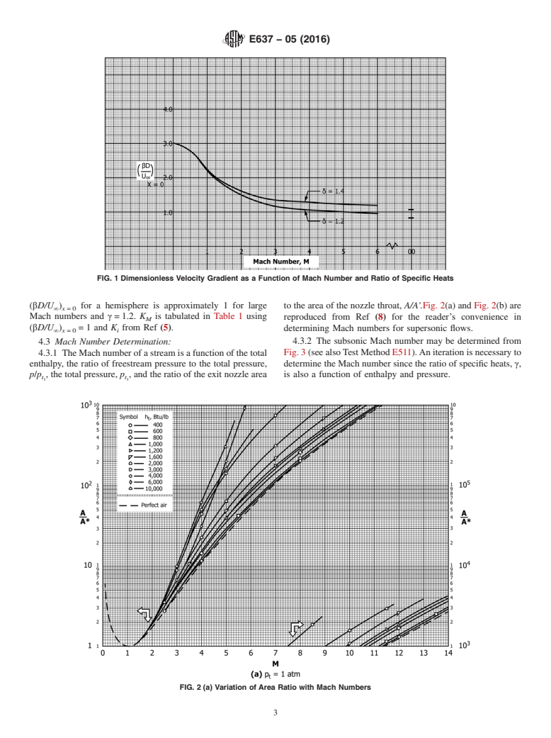
the total pressure, p , and the ratio of the exit nozzle area to the area of the nozzle throat, A/A'.Fig. 2(a) and Fig. 2(b) are reproduced
t
from Ref (8) for the reader’s convenience in determining Mach numbers for supersonic flows.
4.3.2 The subsonic Mach number may be determined from Fig. 3 (see also Test Method E511). An iteration is necessary to
determine the Mach number since the ratio of specific heats, γ, is also a function of enthalpy and pressure.
4.3.3 The ratio of specific heats, γ, is shown as a function of entropy and enthalpy for air in Fig. 4 from Ref (9).S/R is the
dimensionless entropy, and H/RT is the dimensionless enthalpy.
4.4 Velocity Gradient Calculation from Pressure Distribution—The dimensionless stagnation-point velocity gradient may be
obtained from an experimentally measured pressure distribution by using Bernoulli’s compressible flow equation as follows:
γ21 0.5
@12 p/p γ #
U ~ !
t
5 (7)
S D
γ21 0.5
U
` 12 p /p γ
@ ~ ! #
` t
where the velocity ratio may be calculated along the body from the stagnation point. Thus, the dimensionless stagnation-point
velocity gradient, (βD/U ) , is the slope of the U/U and the x/D curve at the stagnation point.
∞ x= 0 ∞
4.5 Model Shape—The nondimensional stagnation-point velocity gradient is a function of the model shape and the Mach
number. For supersonic Mach numbers, the heat transfer relationship between a hemisphere and other axisymmetric blunt bodies
is shown in Fig. 5 (10). In Fig. 5, r is the corner radius, r is the body radius, r is the nose radius, and q˙ is the stagnation-point
c b n s,h
heat transfer rate on a hemisphere. For subsonic Mach numbers, the same type of variation is shown in Fig. 6(6).
4.6 Radiation Effects:
4.6.1 As this test method depends on the accurate determination of the convective stagnation-point heat transfer, any radiant
energy absorbed by the calorimeter surface and incorrectly attributed to the convective mode will directly affect the overall
accuracy of the test method. Generally, the sources of radiant energy are the hot gas stream itself or the gas heating device, or both.
For instance, arc heaters operated at high pressure (10 atm or higher) can produce significant radiant fluxes at the nozzle exit plane.
4.6.2 The proper application requires some knowledge of the radiant environment in the stream at the desired operating
conditions. Usually, it is necessary to measure the radiant heat transfer rate either directly or indirectly. The following is a list of
suggested methods by which the necessary measurements can be made.
FIG. 2 (a) Variation of Area Ratio with Mach Numbers
E637 − 05 (2016)
FIG. 2 (b) Variation of Area Ratio with Mach Numbers (continued)
FIG. 3 Subsonic Pressure Ratio as a Function of Mach Number and γ
4.6.2.1 Direct Measurement with Radiometer—Radiometers are available for the measurement of the incident radiant flux while
excluding the convective heat transfer. In its simplest form, the radiometer is a slug, thin-skin, or circular foil calorimeter with a
E637 − 05 (2016)
FIG. 4 Isentropic Exponent for Air in Equilibrium
sensing area with a coating of known absorptance and covered with some form of window. The purpose of the window is to prevent
convective heat transfer from affecting the calorimeter while transmitting the radiant energy. The window is usually made of quartz
or sapphire. The sensing surface is at the stagnation point of a test probe and is located in such a manner that the view angle is
not restricted. The basic radiometer view angle should be 120° or greater. This technique allows for immersion of the radiometer
in the test stream and direct measurement of the radiant heat transfer rate. There is a major limitation to this technique, however,
in that even with high-pressure water cooling of the radiometer enclosure, the window is poorly cooled and thus the use of windows
is limited to relatively low convective heat transfer conditions or very short exposure times, or both. Also, stream contaminants
coat the window and reduce its transmittance.
4.6.2.2 Direct Measurement with Radiometer Mounted in Cavity—The two limitations noted in 4.6.2.1 may be overcome by
mounting the radiometer at the bottom of a cavity open to the stagnation point of the test probe (see Fig. 7). Good results can be
obtained by using a simple calorimeter in place of the radiometer with a material of known absorptance. When using this
configuration, the measured radiant heat transfer rate is used in the following equation to determine the stagnation-point radi
...
Questions, Comments and Discussion
Ask us and Technical Secretary will try to provide an answer. You can facilitate discussion about the standard in here.