

EN 1915-2:2026
(Main)Aircraft ground support equipment - General requirements - Part 2: Stability and strength requirements, calculations and test methods
- Abstract
This document specifies the conditions to be taken into consideration when calculating the strength and the stability of GSE. It also specifies general test methods.
This part of EN 1915 is intended to be used in conjunction with EN 1915-1:2023, EN ISO 31915-3:2026 (for self-propelled GSE) and EN 1915-4:2004+A1:2009, and with the relevant part of EN 12312 to give the requirements for the types of GSE within the scope of EN 12312.
When EN 12312 does not contain a relevant part for a GSE, EN 1915 (all parts) gives general requirements that may apply, although additional machine specific requirements, to be determined by the manufacturer, are likely to be required.
NOTE The methods given in this document demonstrate one way of achieving an acceptable safety level. Methods that produce comparable results can be used.
This document does not establish additional requirements for the following:
a) operation elsewhere than in an airport environment;
b) operation in severe conditions, e.g. ambient temperature below −20 °C or over 50 °C, tropical or saturated salty atmospheric environment;
c) hazards caused by wind velocity in excess of the figures given in this document;
d) earthquake, flood, landslide, lightning and more generally any natural catastrophe.
This document is not applicable to GSE which are manufactured before the date of publication by CEN of this document.
- Status
- Published
- Publication Date
- 15-Sep-2026
- Technical Committee
- CEN/TC 274 - Aircraft ground support equipment
- Drafting Committee
- CEN/TC 274/WG 1 - Working Group Revision
- Current Stage
- 6060 - Definitive text made available (DAV) - Publishing
- Start Date
- 16-Sep-2026
- Due Date
- 01-Jul-2026
- Completion Date
- 16-Sep-2026

EN 1915-2:2026 is a CEN European Standard for aircraft ground support equipment (GSE). It sets the conditions for calculating strength and stability, and it gives general test methods for designers, manufacturers, and verification teams working on GSE in airport service. It is a Type C standard, so it is meant to be used together with the other EN 1915 parts and the relevant EN 12312 part for the equipment category.
What does EN 1915-2:2026 specify?
EN 1915-2:2026 covers the strength and stability of GSE in an airport environment, together with the general methods used to calculate and verify them. It sits within the EN 1915 family and is intended to be applied with the relevant GSE-specific part of EN 12312.
The document is organized into the following main clauses:
- Scope
- Normative references
- Terms and definitions
- List of hazards
- Safety requirements and/or protective risk reduction measures
- Verification of safety requirements and/or measures
- Information for use
It also includes four annexes.
| Annex | What it covers |
|---|---|
| Annex A | List of significant hazards |
| Annex B | Examples for load geometry |
| Annex C | Wind shape factors |
| Annex ZA | Relationship with Regulation (EU) 2023/1230 |
EN 1915-2:2026 applies to GSE used in an airport environment and does not add requirements for use elsewhere, severe climates, wind above the figures used in the document, or natural catastrophes. It is also not applicable to GSE manufactured before the CEN publication date.
What are the key requirements of EN 1915-2:2026?
EN 1915-2:2026 requires the GSE to be designed and verified for strength and stability using the methods and load cases in Clause 5 and Clause 6. In practice, the document ties together calculation, testing, and the information the manufacturer must provide.
General design approach
Clause 5.1 requires compliance with the strength, stability, and test provisions in this part, plus EN 1915-1, EN ISO 31915-3 for self-propelled GSE, EN 1915-4, and the relevant EN 12312 part. For hazards not specifically covered here, the machine is to be designed using the principles of EN ISO 12100. For a buyer or engineer, that means this part is not a stand-alone document - it is part of a broader family standard.
Strength calculations
Clause 5.2.1 allows several calculation methods, including finite element analysis, truss structure analysis, hand calculations, recognized engineering codes, and actual stress measurements. The technical file has to state the method used and the principal dimensions, materials, and fastening means. In practice, this is the evidence trail that supports the design decision.
The same clause requires second-order theory or large displacement analysis where appropriate, and it addresses global and local stability, including buckling. It also calls for special consideration of exceptional situations such as failure of one lifting element in a system with parallel lifting elements. That matters because the structure has to remain safe even if one element is lost.
Loads, materials, stress and fatigue
Clause 5.2.2 identifies the main load types: dead weight, live load, local loads, snow load, dynamic forces, resonance, and wind load. It also requires the live load to be stated and makes the assumed loading method depend on whether the GSE carries persons. For practical use, that means the manufacturer must define the loading case clearly, not leave it to interpretation.
Clause 5.2.3 requires the technical file to state the materials used, including type, grade, weldability, and relevant mechanical characteristics. Clause 5.2.4 sets stress factors for constructional metal and distinguishes between structural elements and weld types. Clause 5.2.5 covers combined plane stresses, and Clause 5.2.6 requires a fatigue calculation based on the intended load spectrum. For a design team, this means repeated loading cannot be treated as an afterthought.
Safety-related parts
Clause 5.3 gives calculation requirements for safety-related machinery parts such as chain lifting elements, cylinders, pipes and hoses, wire rope lifting elements, winches, winching plants, and stabilizers. It includes minimum strength ratios, rope and chain terminations, drum and pulley proportions, pressure-related checks for hydraulic components, and restrictions such as the use of pneumatic cylinders for stabilizers. In practice, this clause is where many critical component-level decisions are made.
Stability calculations and stability criteria
Clause 5.4 requires stability calculations to include dead weight, live load, snow load where relevant, vertical forces, dynamic forces, secondary dynamic forces, wind load, spring reaction forces, and live load outboard of the tipping edge. It also requires consideration of ground slope, elastic deflection, and, where pneumatic tyres are used, at least one flat tyre in the worst position.
The load cases in Table 3 are combined for different operating states, including work on tyres and on stabilizers, loaded and unloaded, and driving conditions. Clause 5.4.6 defines the stability criterion in terms of restoring moment versus tipping moment. For users, that means stability is checked against realistic operating positions, not just an ideal level surface.
Verification by testing
Clause 6 requires type testing and recording of the results. Strength verification uses test loads positioned to match the calculated load cases, and the test state is set to the worst position and configuration. Stability verification uses tipping tests and, where relevant, dynamic conditions such as full braking from maximum speed. A stability test is successful if the GSE remains on at least three supporting points that are not in one line.
What terms does EN 1915-2:2026 define?
- GSE - In this document, GSE means a complete item of aircraft ground support equipment.
- dead weight - The mass of the part of the GSE for which strength is being calculated.
- live load - The maximum mass, including persons, that the GSE or part of it is intended to carry.
- static test load - A test load or combination of tests used to simulate operational loading.
- wind load - The force acting on a GSE or part of it due to wind pressure.
- tipping edge - The part or parts of the GSE in ground contact that are farthest out on the most heavily loaded side.
- maximum working pressure - The highest pressure at which the system is intended to operate.
- accidental load - A load resulting from unforeseen or rare events such as failure of one lifting device or impacts.
Who uses EN 1915-2:2026?
EN 1915-2:2026 is used by GSE manufacturers, design engineers, and test or verification teams who need to justify strength and stability calculations. It is also relevant to quality and compliance staff who assemble the technical file and to buyers or operators who want to check that the equipment is matched to the intended airport use.
It is especially relevant where the GSE is covered by a specific EN 12312 part, because this document supplies the general strength and stability rules that sit underneath the product-specific requirements.
What changed in EN 1915-2:2026 from the previous edition?
EN 1915-2:2026 supersedes EN 1915-2:2001+A1:2009. The European foreword states these main changes:
- the introduction was updated
- the scope was updated
- the normative references were updated
- requirements for steel constructions were changed to metal or metallic constructions
- the calculation methods were changed
- the bases for stress factors were changed
- the fatigue strength factors were updated
- the document now states when inspections can be dispensed with
- Annex A was added
- Annex ZA was updated
- the bibliography was updated
Which standards are used with EN 1915-2:2026?
| Standard | What it contributes |
|---|---|
| EN 1915-1:2023 | Basic safety requirements for GSE |
| EN ISO 31915-3:2026 | Vibration measurement methods and reduction for self-propelled GSE |
| EN 1915-4:2004+A1:2009 | Noise measurement methods and reduction |
| EN 12312 series | Specific requirements for each GSE category, used together with this general part |
| EN ISO 12100:2010 | Risk assessment and risk reduction principles |
| EN ISO 4413:2010 | Safety requirements for hydraulic systems and components |
| EN 1993-1-9:2025 | Alternative method for fatigue verification |
| ISO 2408:2017 | Requirements for steel wire ropes |
| ISO 8625-1:2018 | Pressure-related vocabulary used in the definitions |
What does the EN 1915-2:2026 document contain?
EN 1915-2:2026 contains calculation methods, test methods, hazard identification, and the supporting geometry and wind data needed to apply them. Annex B gives symbols and load-geometry examples for stability calculations, while Annex C provides the wind shape factors used in wind-load calculations.
The document also contains a hazard list in Annex A and an EU conformity cross-reference in Annex ZA. In practice, these parts are used for design reviews, technical file preparation, type testing, and conformity assessment for airport GSE.
Relations
- Effective Date
- 08-Apr-2024
- Effective Date
- 17-Sep-2026
- Effective Date
- 17-Sep-2026
- Effective Date
- 17-Sep-2026
- Effective Date
- 17-Sep-2026
- Effective Date
- 17-Sep-2026
- Effective Date
- 17-Sep-2026
- Effective Date
- 17-Sep-2026
- Effective Date
- 17-Sep-2026
- Effective Date
- 17-Sep-2026
- Effective Date
- 17-Sep-2026
- Effective Date
- 17-Sep-2026
- Effective Date
- 17-Sep-2026
- Effective Date
- 17-Sep-2026
- Effective Date
- 17-Sep-2026
Get Certified
Connect with accredited certification bodies for this standard

BUREAU VERITAS Certification Germany
Bureau Veritas certification in Germany.

Element Materials Technology
Materials testing and product certification.

AQMS Ltd.
AQMS provides ISO certification to SMEs across the UK.
Sponsored listings
Frequently Asked Questions
EN 1915-2:2026 is a standard published by the European Committee for Standardization (CEN). Its full title is "Aircraft ground support equipment - General requirements - Part 2: Stability and strength requirements, calculations and test methods". This standard covers: This document specifies the conditions to be taken into consideration when calculating the strength and the stability of GSE. It also specifies general test methods. This part of EN 1915 is intended to be used in conjunction with EN 1915-1:2023, EN ISO 31915-3:2026 (for self-propelled GSE) and EN 1915-4:2004+A1:2009, and with the relevant part of EN 12312 to give the requirements for the types of GSE within the scope of EN 12312. When EN 12312 does not contain a relevant part for a GSE, EN 1915 (all parts) gives general requirements that may apply, although additional machine specific requirements, to be determined by the manufacturer, are likely to be required. NOTE The methods given in this document demonstrate one way of achieving an acceptable safety level. Methods that produce comparable results can be used. This document does not establish additional requirements for the following: a) operation elsewhere than in an airport environment; b) operation in severe conditions, e.g. ambient temperature below −20 °C or over 50 °C, tropical or saturated salty atmospheric environment; c) hazards caused by wind velocity in excess of the figures given in this document; d) earthquake, flood, landslide, lightning and more generally any natural catastrophe. This document is not applicable to GSE which are manufactured before the date of publication by CEN of this document.
This document specifies the conditions to be taken into consideration when calculating the strength and the stability of GSE. It also specifies general test methods. This part of EN 1915 is intended to be used in conjunction with EN 1915-1:2023, EN ISO 31915-3:2026 (for self-propelled GSE) and EN 1915-4:2004+A1:2009, and with the relevant part of EN 12312 to give the requirements for the types of GSE within the scope of EN 12312. When EN 12312 does not contain a relevant part for a GSE, EN 1915 (all parts) gives general requirements that may apply, although additional machine specific requirements, to be determined by the manufacturer, are likely to be required. NOTE The methods given in this document demonstrate one way of achieving an acceptable safety level. Methods that produce comparable results can be used. This document does not establish additional requirements for the following: a) operation elsewhere than in an airport environment; b) operation in severe conditions, e.g. ambient temperature below −20 °C or over 50 °C, tropical or saturated salty atmospheric environment; c) hazards caused by wind velocity in excess of the figures given in this document; d) earthquake, flood, landslide, lightning and more generally any natural catastrophe. This document is not applicable to GSE which are manufactured before the date of publication by CEN of this document.
EN 1915-2:2026 is classified under the following ICS (International Classification for Standards) categories: 49.100 - Ground service and maintenance equipment. The ICS classification helps identify the subject area and facilitates finding related standards.
EN 1915-2:2026 has the following relationships with other standards: It is inter standard links to EN 1915-2:2001+A1:2009, EN 12312-16:2005+A1:2009, EN 12312-18:2005+A1:2009, EN 12312-10:2005+A1:2009, EN 12312-11:2005, EN 12312-12:2017, EN 12312-7:2005+A1:2009, EN 12312-9:2013, EN 12312-15:2006+A1:2009, EN 12312-19:2005+A1:2009, EN 12312-9:2005+A1:2009, EN 12312-20:2005+A1:2009, EN 12312-4:2003+A1:2009, EN 12312-5:2005+A1:2009, EN 12312-8:2005+A1:2009. Understanding these relationships helps ensure you are using the most current and applicable version of the standard.
EN 1915-2:2026 is associated with the following European legislation: EU Directives/Regulations: 2006/42/EC, 2023/1230; Standardization Mandates: M/396, M/605. When a standard is cited in the Official Journal of the European Union, products manufactured in conformity with it benefit from a presumption of conformity with the essential requirements of the corresponding EU directive or regulation.
EN 1915-2:2026 is available in PDF format for immediate download after purchase. The document can be added to your cart and obtained through the secure checkout process. Digital delivery ensures instant access to the complete standard document.
Standards Content (Sample)
SLOVENSKI STANDARD
01-november-2026
Podporna oprema na tleh za letalski promet - Splošne zahteve - 2. del: Zahteve za
stabilnost in vzdržljivost, izračuni in preskusni postopki
Aircraft ground support equipment - General requirements - Part 2: Stability and strength
requirements, calculations and test methods
Luftfahrt-Bodengeräte - Allgemeine Anforderungen - Teil 2: Standsicherheits- und
Festigkeitsanforderungen, Berechnungen und Prüfverfahren
Matériel au sol pour aéronefs - Exigences générales - Partie 2: Prescriptions de stabilité
et de résistance mécanique, calculs et méthodes d'essai
Ta slovenski standard je istoveten z: EN 1915-2:2026
ICS:
49.100 Oprema za servis in Ground service and
vzdrževanje na tleh maintenance equipment
2003-01.Slovenski inštitut za standardizacijo. Razmnoževanje celote ali delov tega standarda ni dovoljeno.
EN 1915-2
EUROPEAN STANDARD
NORME EUROPÉENNE
September 2026
EUROPÄISCHE NORM
ICS 49.100 Supersedes EN 1915-2:2001+A1:2009
English Version
Aircraft ground support equipment - General
requirements - Part 2: Stability and strength requirements,
calculations and test methods
Matériel au sol pour aéronefs - Exigences générales - Luftfahrt-Bodengeräte - Allgemeine Anforderungen -
Partie 2 : Exigences de stabilité et de résistance Teil 2: Standsicherheits- und
mécanique, calculs et méthodes d'essai Festigkeitsanforderungen, Berechnungen und
Prüfverfahren
This European Standard was approved by CEN on 5 July 2026.
CEN members are bound to comply with the CEN/CENELEC Internal Regulations which stipulate the conditions for giving this
European Standard the status of a national standard without any alteration. Up-to-date lists and bibliographical references
concerning such national standards may be obtained on application to the CEN-CENELEC Management Centre or to any CEN
member.
This European Standard exists in three official versions (English, French, German). A version in any other language made by
translation under the responsibility of a CEN member into its own language and notified to the CEN-CENELEC Management
Centre has the same status as the official versions.
CEN members are the national standards bodies of Austria, Belgium, Bulgaria, Croatia, Cyprus, Czech Republic, Denmark, Estonia,
Finland, France, Germany, Greece, Hungary, Iceland, Ireland, Italy, Latvia, Lithuania, Luxembourg, Malta, Netherlands, Norway,
Poland, Portugal, Republic of North Macedonia, Romania, Serbia, Slovakia, Slovenia, Spain, Sweden, Switzerland, Türkiye and
United Kingdom.
EUROPEAN COMMITTEE FOR STANDARDIZATION
COMITÉ EUROPÉEN DE NORMALISATION
EUROPÄISCHES KOMITEE FÜR NORMUNG
CEN-CENELEC Management Centre: Rue de la Science 23, B-1040 Brussels
© 2026 CEN All rights of exploitation in any form and by any means reserved Ref. No. EN 1915-2:2026 E
worldwide for CEN national Members.
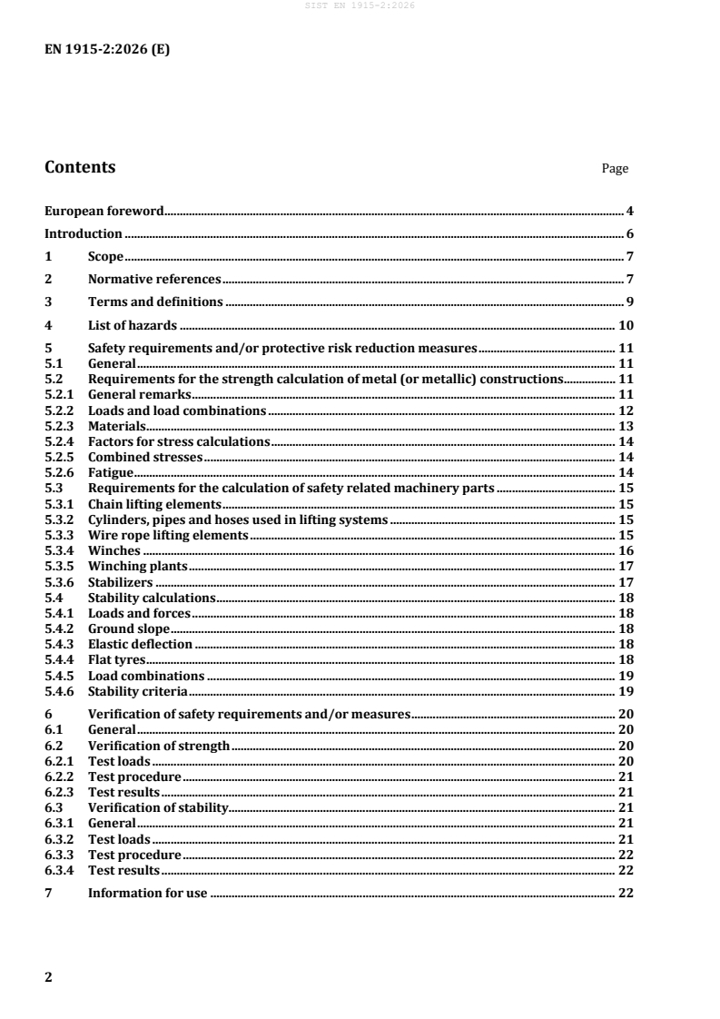
Contents Page
European foreword . 4
Introduction . 6
1 Scope . 7
2 Normative references . 7
3 Terms and definitions . 9
4 List of hazards . 10
5 Safety requirements and/or protective risk reduction measures . 11
5.1 General . 11
5.2 Requirements for the strength calculation of metal (or metallic) constructions . 11
5.2.1 General remarks . 11
5.2.2 Loads and load combinations . 12
5.2.3 Materials . 13
5.2.4 Factors for stress calculations . 14
5.2.5 Combined stresses . 14
5.2.6 Fatigue . 14
5.3 Requirements for the calculation of safety related machinery parts . 15
5.3.1 Chain lifting elements . 15
5.3.2 Cylinders, pipes and hoses used in lifting systems . 15
5.3.3 Wire rope lifting elements . 15
5.3.4 Winches . 16
5.3.5 Winching plants . 17
5.3.6 Stabilizers . 17
5.4 Stability calculations . 18
5.4.1 Loads and forces . 18
5.4.2 Ground slope . 18
5.4.3 Elastic deflection . 18
5.4.4 Flat tyres . 18
5.4.5 Load combinations . 19
5.4.6 Stability criteria . 19
6 Verification of safety requirements and/or measures . 20
6.1 General . 20
6.2 Verification of strength . 20
6.2.1 Test loads . 20
6.2.2 Test procedure . 21
6.2.3 Test results . 21
6.3 Verification of stability. 21
6.3.1 General . 21
6.3.2 Test loads . 21
6.3.3 Test procedure . 22
6.3.4 Test results . 22
7 Information for use . 22
Annex A (informative) List of significant hazards . 23
Annex B (informative) Examples for load geometry . 24
Annex C (normative) Wind shape factors . 30
Annex ZA (informative) Relationship between this European Standard and the essential
requirements of Regulation (EU) 2023/1230 aimed to be covered. 32
Bibliography . 37
European foreword
This document (EN 1915-2:2026) has been prepared by Technical Committee CEN/TC 274 “Aircraft
ground support equipment”, the secretariat of which is held by DIN.
This European Standard shall be given the status of a national standard, either by publication of an
identical text or by endorsement, at the latest by March 2027, and conflicting national standards shall be
withdrawn at the latest by March 2027.
Attention is drawn to the possibility that some of the elements of this document may be the subject of
patent rights. CEN shall not be held responsible for identifying any or all such patent rights.
This document supersedes EN 1915-2:2001+A1:2009.
This document includes the following significant technical changes with respect to EN 1915-
2:2001+A1:2009:
a) the Introduction was updated;
b) the Scope was updated;
c) Clause 2, Normative references, was updated;
d) requirements for steel constructions changed to metal (or metallic) constructions;
e) the methods of calculation changed;
f) factors for stress calculations have new bases;
g) fatigue strength factors were updated;
h) it has been determined when inspections can be dispensed with (see 6.1);
i) Annex A, List of significant hazards, was added;
j) Annex ZA was updated;
k) the Bibliography was updated.
This document has been prepared under a standardization request addressed to CEN by the European
Commission. The Standing Committee of the EFTA States subsequently approves these requests for its
Member States.
For the relationship with EU Legislation, see informative Annex ZA, which is an integral part of this
document.
EN 1915, Aircraft ground support equipment ― General requirements, consists of the following parts:
— Part 1: Basic safety requirements;
— Part 2: Stability and strength requirements, calculations and test methods (the present document);
— Part 3: Vibration measurement methods and reduction;
— Part 4: Noise measurement methods and reduction.
EN 12312, Aircraft ground support equipment ― Specific requirements, consists of the following parts:
— Part 1: Passenger stairs;
— Part 2: Catering vehicles;
— Part 3: Conveyor belt vehicles;
— Part 4: Passenger boarding bridges;
— Part 5: Aircraft fuelling equipment;
— Part 6: Deicers and deicing/antiicing equipment;
— Part 7: Aircraft movement equipment;
— Part 8: Maintenance or service stairs and platforms;
— Part 9: Container/Pallet loaders;
— Part 10: Container/Pallet transfer transporters;
— Part 11: Container/Pallet dollies and loose load trailers;
— Part 12: Potable water service equipment;
— Part 13: Lavatory service equipment;
— Part 14: Disabled/incapacitated passenger boarding vehicles;
— Part 15: Baggage and equipment tractors;
— Part 16: Air start equipment;
— Part 17: Air conditioning equipment;
— Part 18: Nitrogen or Oxygen units;
— Part 19: Aircraft jacks, axle jacks and hydraulic tail stanchions;
— Part 20: Electrical ground power units.
Any feedback and questions on this document should be directed to the users’ national standards body.
A complete listing of these bodies can be found on the CEN website.
According to the CEN-CENELEC Internal Regulations, the national standards organisations of the
following countries are bound to implement this European Standard: Austria, Belgium, Bulgaria, Croatia,
Cyprus, Czech Republic, Denmark, Estonia, Finland, France, Germany, Greece, Hungary, Iceland, Ireland,
Italy, Latvia, Lithuania, Luxembourg, Malta, Netherlands, Norway, Poland, Portugal, Republic of North
Macedonia, Romania, Serbia, Slovakia, Slovenia, Spain, Sweden, Switzerland, Türkiye and the United
Kingdom.
Introduction
The abbreviation GSE means a complete item of aircraft ground support equipment in the context of this
document.
When compiling this document, it was assumed that:
a) components without specific requirements are:
1) designed in accordance with good engineering practice and calculation codes;
2) of sound mechanical and electrical construction;
3) made of materials with adequate strength and of suitable quality;
4) made of materials free of defects;
b) components are kept in good repair and working order, so that the required characteristics remain
despite wear;
c) by design of the load bearing elements, a safe operation of the machine is ensured for loading ranges
from zero to 100 % of the rated possibilities and during tests;
d) a negotiation took place between the user and the manufacturer concerning particular conditions for
the use and places of use of the GSE;
e) the place of operation allows a safe use of GSE.
The extent to which hazards are covered is indicated in the scope of this document.
The minimum essential criteria are considered to be of primary importance in providing safe, economical
and usable GSE. Deviation from the recommended methods and conditions should occur only after careful
consideration, extensive testing and thorough in-service evaluation have shown alternative methods or
conditions to be satisfactory. Such deviations are outside the scope of this document and a manufacturer
should be able to demonstrate an equivalent level of protection.
This European Standard is a Type C standard as defined in EN ISO 12100:2010.
The machinery concerned and the extent to which hazards, hazardous situations or hazardous events are
covered are indicated in the Scope of this document.
When requirements of this type C standard are different from those which are stated in type A or type B
standards, the requirements of this type C standard take precedence over the requirements of the other
standards for machines that have been designed and built according to the requirements of this type C
standard.
1 Scope
This document specifies the conditions to be taken into consideration when calculating the strength and
the stability of GSE. It also specifies general test methods.
This part of EN 1915 is intended to be used in conjunction with EN 1915-1:2023, EN ISO 31915-3:2026
(for self-propelled GSE) and EN 1915-4:2004+A1:2009, and with the relevant part of EN 12312 to give
the requirements for the types of GSE within the scope of EN 12312.
When EN 12312 does not contain a relevant part for a GSE, EN 1915 (all parts) gives general
requirements that may apply, although additional machine specific requirements, to be determined by
the manufacturer, are likely to be required.
NOTE The methods given in this document demonstrate one way of achieving an acceptable safety level.
Methods that produce comparable results can be used.
This document does not establish additional requirements for the following:
a) operation elsewhere than in an airport environment;
b) operation in severe conditions, e.g. ambient temperature below −20 °C or over 50 °C, tropical or
saturated salty atmospheric environment;
c) hazards caused by wind velocity in excess of the figures given in this document;
d) earthquake, flood, landslide, lightning and more generally any natural catastrophe.
This document is not applicable to GSE which are manufactured before the date of publication by CEN of
this document.
2 Normative references
The following documents are referred to in the text in such a way that some or all of their content
constitutes requirements of this document. For dated references, only the edition cited applies. For
undated references, the latest edition of the referenced document (including any amendments) applies.
EN 1915-1:2023, Aircraft ground support equipment — General requirements — Part 1: Basic safety
requirements
EN ISO 31915-3:2026, Aircraft ground support equipment — General requirements — Part 3: Vibration
measurement methods and reduction
EN 1915-4:2004+A1:2009, Aircraft ground support equipment — General requirements — Part 4: Noise
measurement methods and reduction
EN 1993-1-9:2025, Eurocode 3: Design of steel structures — Part 1-9: Fatigue
EN 12312-1:2024, Aircraft ground support equipment — Specific requirements — Part 1: Passenger stairs
EN 12312-2:2014, Aircraft ground support equipment — Specific requirements — Part 2: Catering vehicles
EN 12312-3:2017+A1:2020, Aircraft ground support equipment — Specific requirements — Part 3:
Conveyor belt vehicles
EN 12312-4:2024, Aircraft ground support equipment — Specific requirements — Part 4: Passenger
boarding bridges
EN 12312-5:2021+A1:2025, Aircraft ground support equipment — Specific requirements — Part 5:
Aircraft fuelling equipment
EN 12312-6:2017, Aircraft ground support equipment — Specific requirements — Part 6: Deicers and de-
icing/anti-icing equipment
EN 12312-7:2020, Aircraft ground support equipment — Specific requirements — Part 7: Aircraft
movement equipment
EN 12312-8:2018, Aircraft ground support equipment — Specific requirements — Part 8: Maintenance or
service stairs and platforms
EN 12312-9:2013, Aircraft ground support equipment — Specific requirements — Part 9: Container/Pallet
loaders
EN 12312-10:2005+A1:2009, Aircraft ground support equipment — Specific requirements — Part 10:
Container/Pallet transfer transporters
EN 12312-11:2005, Aircraft ground support equipment — Specific requirements — Part 11:
Container/Pallet dollies and loose load trailers
EN 12312-12:2017, Aircraft ground support equipment — Specific requirements — Part 12: Potable water
service equipment
EN 12312-13:2017, Aircraft ground support equipment — Specific requirements — Part 13: Lavatory
service equipment
EN 12312-14:2014, Aircraft ground support equipment — Specific requirements — Part 14:
Disabled/incapacitated passenger boarding vehicles
EN 12312-15:2020+A2:2025, Aircraft ground support equipment — Specific requirements — Part 15:
Baggage and equipment tractors
EN 12312-16:2005+A1:2009, Aircraft ground support equipment — Specific requirements — Part 16: Air
start equipment
EN 12312-17:2004+A1:2009, Aircraft ground support equipment — Specific requirements — Part 17: Air
conditioning equipment
EN 12312-18:2005+A1:2009, Aircraft ground support equipment — Specific requirements — Part 18:
Nitrogen or Oxygen units
EN 12312-19:2005+A1:2009, Aircraft ground support equipment — Specific requirements — Part 19:
Aircraft jacks, axle jacks and hydraulic tail stanchions
EN 12312-20:2026, Aircraft ground support equipment — Specific requirements — Part 20: Electrical
ground power units
EN ISO 4413:2010, Hydraulic fluid power — General rules and safety requirements for systems and their
components (ISO 4413:2010)
EN ISO 12100:2010, Safety of machinery — General principles for design — Risk assessment and risk
reduction (ISO 12100:2010)
ISO 2408:2017, Steel wire ropes — Requirements
ISO 8625-1:2018, Aerospace — Fluid systems — Vocabulary — Part 1: General terms and definitions
related to pressure
3 Terms and definitions
For the purposes of this document, the terms and definitions given in EN ISO 12100:2010, EN 1915-
1:2023 and ISO 8625-1:2018, and the following apply.
ISO and IEC maintain terminology databases for use in standardization at the following addresses:
— ISO Online browsing platform: available at https://www.iso.org/obp/
— IEC Electropedia: available at https://www.electropedia.org/
3.1
dead weight
mass of that part of the GSE, for which the strength is to be calculated
3.2
live load
maximum mass (including persons) a GSE or a part of it is intended to carry
3.3
local loads
loads derived from the live load for the calculation of the strength of particular parts of the GSE
3.4
snow load
maximum mass of snow or ice the GSE is intended to carry
3.5
static test load
test load or combination of tests, used to simulate operational loading
3.6
dynamic forces
forces resulting from acceleration of a mass
EXAMPLE Acceleration forces, retardation forces, centrifugal forces.
3.7
secondary dynamic forces
forces caused by the movement of persons
Note 1 to entry: These forces act horizontally at the centre of gravity of the body of a person. The centre of gravity
of persons is assumed to be 1,1 m above the standing area.
3.8
retardation forces
forces on particular parts of GSE caused by the maximum deceleration of the GSE
Note 1 to entry: These forces act at the centre of gravity of the particular part in the direction of motion.
3.9
spring reaction force
force in the suspension under the condition of loading
3.10
wind load
force acting on a GSE or part of it due to wind pressure
Note 1 to entry: This force acts horizontally at the geometric centre of the body of the GSE.
3.11
tipping edge
those part(s) of the GSE in contact with the ground, located farthest out on the most heavily loaded side
3.12
tipping moment
total of the products of those forces which tend to tip the GSE, and their distance normal to the tipping
edge
3.13
burst pressure, actual
pressure at which a component bursts or shows excessive leakage due to structural failure
[SOURCE: ISO 8625-1:2018, 3.7]
3.14
maximum working pressure
highest pressure at which the system is to operate
3.15
accidental load
that load resulting from unforeseen or rare events
Note 1 to entry: Those events can be e.g. failure of one lifting device and impacts.
3.16
resonance
phenomenon where a system vibrates with maximum amplitude at specific frequencies, known as natural
frequencies
Note 1 to entry: Resonance can only be considered during the intended use of the GSE, e.g. passengers at
passenger boarding bridges.
4 List of hazards
This list of risks and hazards (given in Table A.1) is based on EN ISO 12100:2010 and contains the hazards
and hazardous situations, as far as they are dealt with in this document, identified by risk assessment as
significant for this type of machinery and which require action to eliminate or reduce risks. See also the
complementary list of hazards in the other parts of EN 1915 and in the different parts of EN 12312.
5 Safety requirements and/or protective risk reduction measures
5.1 General
GSE shall comply with the safety requirements and/or protective measures of this clause, with the
requirements of EN 1915-1:2023, EN ISO 31915-3:2026 and EN 1915-4:2004+A1:2009 as relevant, as
well as with the requirements of the relevant part of EN 12312. In addition, the machine shall be designed
according to the principles of EN ISO 12100:2010 for relevant but not significant hazards, which are not
dealt with by this document.
Where a standard automotive or truck chassis is used, the manufacturer of the GSE should pay attention
to and appropriate gross mass rating for the intended use.
5.2 Requirements for the strength calculation of metal (or metallic) constructions
5.2.1 General remarks
The method of calculation shall take into account the complexity of each individual type of GSE. The
pertinence of the method of calculation shall be stated in the technical file.
Calculation models shall be performed either by
a) finite element analysis;
b) truss structure analysis;
c) hand calculations
or combinations of these.
Design verification methods shall be performed either by
d) recognized engineering design methods and engineering codes;
e) actual stress measurements
or combinations of these.
NOTE Information about load geometry is given in Annex B, Table B.1 and Figures B.1 to B.5.
The source of the design methods and engineering codes, if generally accessible, shall be stated in the
case of any unusual formulae or calculation methods. Otherwise, only formulae or calculation methods
which can be verified shall be used.
The general stress analysis shall be carried out to ensure safe levels of stress in relation to the yield stress
of the material used.
Safe levels of stress related to the loading conditions shall be demonstrated for all supporting structures.
The principal dimensions, cross sections, materials and fastening means shall be stated.
The calculation shall be performed considering second order theory or large displacements analysis. Test
results, if available, shall be used to modify calculation parameters. The analysis of the load case
combinations intended shall be carried out to ensure that the severest individual load ratings can be
identified.
The global and local stability (buckling) of the GSE shall be proven according to design verification
methods given in 5.2.1. Eigenvalue buckling analysis is permitted.
Consideration shall be given to high dynamic forces which can be caused by the operation of a safety
device for the prevention of unintentional movements if there is an escape of fluid in a piping system or
a rope, chain, nut or gear fails.
The design of mechanical restraint devices shall take into account all loads and forces occurring during
blocking.
Where a system has two or more lifting elements in parallel, design shall ensure the loads resulting from
the failure of one element shall not have effects jeopardising safety. These loads shall be considered in
structural design to ensure the safety and integrity of the structure under exceptional circumstances. The
structure shall be stable but plastic deformations and / or local instabilities are allowed. The loading
condition for this accidental case shall be the combination of all vertical loads: 1,0 × dead weight +
1,1 × (live load + snow load). Resonance effects shall be avoided for live load.
Strength calculations can be performed using recognized methods such as Eurocode 3 for steel structures
(EN 1993-1-3:2024), the FKM-Guidelines, Computational strength verification of machine components ,
EN 13001-2:2021 or other recognized calculation methods.
5.2.2 Loads and load combinations
5.2.2.1 The following loads or worse combinations thereof shall be taken into account:
a) dead weight;
b) live load;
c) local loads;
d) snow load;
e) dynamic forces;
f) resonance;
g) wind load.
NOTE Load combinations are given in 5.4.5.
5.2.2.2 Loads shall be used in the calculation of the strength of the elements concerned at the most
unfavourable positions, values and directions, e.g. Table 3.
5.2.2.3 The live load shall be stated, and shall be not less than 3200 N/m . Where the intended use
of the GSE is to carry persons, the live load shall be calculated on the basis of four persons per m , each
person at 80 kg.
5.2.2.4 Dynamic forces effective at the same time shall be measured under intended use conditions
or be calculated.
For GSE not designed to be driven during operation, vertical dynamic forces shall be considered to be at
least 10 % of the component mass and live load, subject to verification by a competent authority.
NOTE See also the EN 12312 series.
Available from: VDMA Services GmbH, Lyoner Straße 18, D-60528 Frankfurt am Main, Germany.
5.2.2.5 For simplification of the calculation, secondary dynamic forces are introduced into the
calculation as static forces by the formula:
F = 200 N x Σ (1/i)
s
i.e. F = 200 N (1/1+1/2+1/3+.+1/i)
s
where:
i is the number of persons on the entire GSE.
5.2.2.6 The snow load shall be specified in the manufacturer instruction manual.
NOTE The snow load is depending on the geographical area of use of the GSE and can be agreed between
manufacturer and user (see introduction – negotiation).
5.2.2.7 The wind force is generally calculated by the formula:
W = c q A
where:
c is the shape factor;
A is the surface area in square metres;
q is the dynamic wind pressure in Pascals.
The dynamic wind pressure is calculated by the formula:
ρv
q =
where:
v is the wind velocity, in metres per second;
ρ is the density of air in kilograms per cubic metre.
An air density at the lowest operating temperature shall always be used. As a reference, at an operating
temperature of +15 °C, an air density of 1,225 kg per cubic metre can be used.
The maximum wind velocity shall be specified in the manufacturer instruction manual. A minimum
constant wind velocity of 20,58 m/s (40 kn) shall be considered.
NOTE The operating conditions to resist higher wind gust velocities can be agreed between manufacturer and
user (see introduction – negotiation).
For simplification, the wind velocity shall be assumed to be constant over the height of the GSE.
The shape factor c is given in Annex C, Table C.1 and Figures C.1 to C.3.
5.2.3 Materials
Type, grade, chemical composition, weldability and mechanical characteristics (e.g. yield strength,
modulus of elasticity, shear modulus) of materials used shall be stated in the technical file.
5.2.4 Factors for stress calculations
The stress factors S as specified in Table 1 are applicable for constructional metal up to a yield of
355 N/mm .
Only for accidental load, local plastic analysis is allowed.
Table 1 — Stress factors S
a a
Structural elements
Butt welds Fillet welds
Equivalent stress σ 1,3 1,7 (1,4) 2,1 (1,7)
V
Tensile stress σ
Z
Compressive stress σ 1,4 1,7 (1,4) 1,8 (1,5)
D
Shear stress τ 1,7 2,1 (1,7) 2,1 (1,7)
a
The stress factors between brackets can be used for welding quality B according to EN ISO 5817:2023 and
welds in accordance with EN ISO 3834-1:2021, EN ISO 3834-2:2021, EN ISO 3834-3:2021 and EN ISO 3834-
4:2021.
The established stress resulting from the multiplication of the calculated stress by the stress factor S shall
not exceed the yield stress of the respective material.
5.2.5 Combined stresses
Where situations of combined plane stresses exist, the equivalent stress shall be verified, paying attention
to the plus or minus signs, as follows:
2 2 2
σ σσσ+ − σ + 3τ
v x y x y
5.2.6 Fatigue
A fatigue calculation shall be carr
...