

IEC 60076-4:2026
(Main)Power transformers - Part 4: Lightning impulse and switching impulse tests of power transformers and reactors
- Abstract
CORRECTED VERSION 2026-09
IEC 60076-4:2026 applies to lightning and switching impulse tests on power transformers and reactors. Information is given on waveforms, test circuits including test connections, earthing practices, failure detection methods, test procedures, measuring techniques and interpretation of results.
- Status
- Published
- Publication Date
- 08-Jul-2026
- Technical Committee
- TC 14 - Power transformers
- Drafting Committee
- MT 60076-4 - TC 14/MT 60076-4
- Current Stage
- PPUB - Publication issued
- Start Date
- 09-Jul-2026
- Completion Date
- 08-May-2026
Buy Documents
IEC 60076-4:2026 - Power transformers - Part 4: Lightning impulse and switching impulse tests of power transformers and reactors
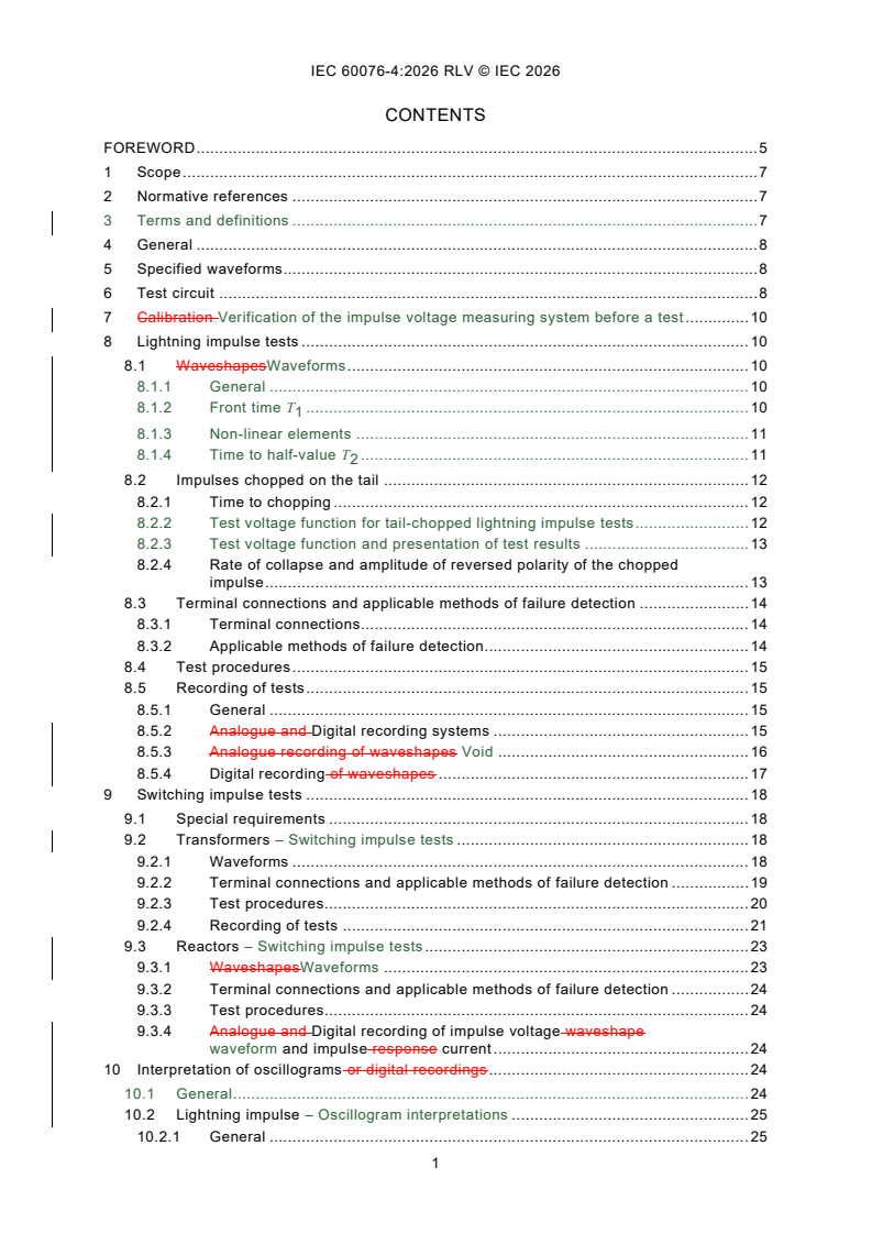
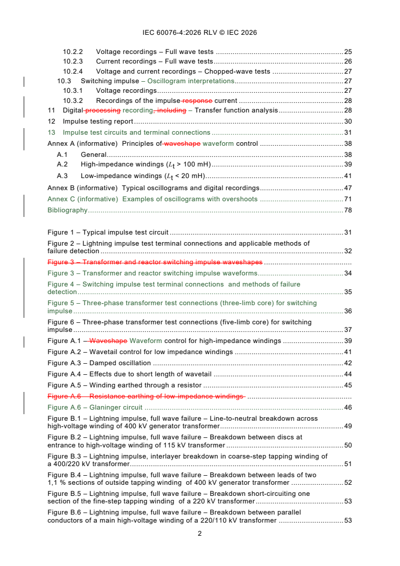
REDLINE IEC 60076-4:2026 RLV - Power transformers - Part 4: Lightning impulse and switching impulse tests of power transformers and reactors
IEC 60076-4:2026 - Transformateurs de puissance - Partie 4: Essais au choc de foudre et au choc de manouvre des transformateurs de puissance et bobines d'inductance
iec60076-4{ed2.0}en - IEC 60076-4:2026 - Power transformers - Part 4: Lightning impulse and switching impulse tests of power transformers and reactors
IEC 60076-4:2026 is an IEC guide for lightning impulse and switching impulse tests on power transformers and reactors. It supplements IEC 60076-3 by explaining the test waveforms, circuits, earthing, failure detection, measuring techniques, recording, and result interpretation that test laboratories, manufacturers, and purchasers use to run and review impulse tests.
What does IEC 60076-4:2026 specify?
IEC 60076-4:2026 covers lightning and switching impulse testing for power transformers and reactors. It gives guidance on how to set up the test, how to shape and measure the impulse, how to detect failure, and how to read the records.
The document is organized into 13 clauses and 3 informative annexes:
- Clauses 1-3 cover scope, normative references, and terms used in the document.
- Clause 4 gives the general approach and explains how transformers and reactors differ.
- Clause 5 points to the specified waveforms used for impulse testing.
- Clause 6 describes the test circuit.
- Clause 7 covers verification of the impulse voltage measuring system before a test.
- Clause 8 covers lightning impulse tests.
- Clause 9 covers switching impulse tests, with separate treatment for transformers and reactors.
- Clauses 10-12 deal with interpretation, digital processing, and reporting.
- Clause 13 shows impulse test circuits and terminal connections.
| Annex | What it covers |
|---|---|
| Annex A | Principles of waveform control, including high-impedance and low-impedance windings |
| Annex B | Typical oscillograms and digital recordings from actual tests, including fault and non-fault cases |
| Annex C | Examples of lightning impulse oscillograms with overshoots and their assessment |
What are the key requirements of IEC 60076-4:2026?
IEC 60076-4:2026 focuses on how to produce, measure, compare, and record impulse tests so the results can be interpreted consistently. The most important points are in Clauses 4 to 12 and Annex A.
Test method and equipment setup
Clause 4 bases the document on conventional impulse generators for lightning and switching impulse tests. It also allows switching impulse generation by discharging a separate capacitor into an intermediate or low-voltage winding, but it does not apply the method that uses an added series inductance to create slightly damped oscillations.
Clause 4 also separates transformer and reactor practice. For transformers, lightning impulse tests can be applied to all terminals and windings at specific levels, while switching impulse testing is limited by the induced voltage transferred to the other winding. For reactors, lightning impulse tests are treated much like transformer tests, but switching impulse testing has different circuit and stress considerations.
Waveforms and circuit parameters
Clause 5 ties the test waveforms to IEC 60076-3, IEC 60076-6, and IEC 60060-1. In practice, that means the waveform is not chosen ad hoc - it is the one already specified for the equipment and evaluated with the high-voltage test methods in the IEC 60060 series.
Clause 6 divides the setup into the main circuit, the voltage measuring circuit, and the chopping circuit where applicable. It also explains what changes the impulse waveform: the test object capacitance and inductance, generator capacitance, series resistance, stray inductance and capacitance, chopping equipment, and non-linear elements in the transformer. This matters because small changes in the test circuit can change the recorded pulse shape and the apparent test result.
Verification before the test
Clause 7 requires the impulse voltage measuring system to be verified in accordance with IEC 60060. A pre-test check of the circuit at a lower voltage is allowed, using a sphere gap or comparison with another approved device, but that check does not replace calibration of the approved measuring system. After any check, the circuit must not be altered except to remove the checking devices.
Lightning impulse tests
Clause 8 covers full-wave and tail-chopped lightning impulse tests. It states that the preferred method is direct application, while the transferred surge method may be used in special cases when the intermediate or low-voltage winding cannot in service be subjected to lightning overvoltage from the connected system.
Clause 8 also gives practical rules for chopped waves. A time to chopping of up to 6 µs can be accepted if the peak value is reached before the chop. It also notes that chopped-wave oscillograms or digital records are only comparable when the times to chopping are almost the same. For a test engineer, that means chopped-wave records must be compared very carefully and only against similar conditions.
Clause 8 further explains that non-linear protection devices can change the reduced full-wave and full-wave records. To show that these differences come from the device operation and not from a fault, the document calls for several reduced full-wave shots at different voltage levels and a reversed test sequence to demonstrate reversibility.
Switching impulse tests
Clause 9 treats transformers and reactors separately because their magnetic behavior under switching impulses is different. For transformers, the long switching impulse allows significant core flux to build up. For reactors, the waveform problem is different and the test must be adjusted to the winding characteristics.
For reactor switching impulse tests, Clause 9.3.1 gives practical waveform limits so the winding is stressed without creating avoidable turn-to-turn or flashover risk. The front time should not be too short, the opposite polarity peak should stay within a safe level, and larger reactors may need relaxed timing values if using a standard transformer test generator would require excessive extension. In practice, this tells the test lab how to shape the pulse so the reactor sees realistic insulation stress without an unstable waveform.
Clause 9.2.3.2 also links transformer switching impulse testing with no-load loss. That helps users who need to relate the impulse test result to the transformer’s magnetic behavior during the test.
Interpretation and digital analysis
Clause 10 says the basic way to judge a test is to compare records from the same channel under the same test conditions and circuit parameters. If voltage levels differ, the records should be corrected by appropriate attenuation so the comparison is fair. Clause 10 also warns that the same-looking discrepancy can mean different things on different designs, so examples help but do not replace engineering judgment.
Clause 11 adds digital processing and transfer function analysis. The applied voltage and the impulse response current are transformed by Fast Fourier Transformation (FFT) into the frequency domain. The preferred analysis is the transfer admittance function, because the voltage spectrum has no zero points. A shift in significant poles indicates part-winding breakdown, while pole flattening suggests partial discharges. If the current or voltage changes but the transfer-admittance function does not, the issue is more likely in the test circuit than in the test object.
Reporting and documentation
Clause 12 requires the impulse test report to include equipment identification, serial number, tap position, place and date of test, personnel, the standard used, specified test levels and waveforms, the actual test setup, the earthing arrangement, the measurement positions, and the relevant recordings. The report must show axis scaling on each oscillogram or digital record, and overlays of voltage and current waveforms are part of the report. In practice, this is what lets another engineer reconstruct the test conditions and compare results later.
Annex A supports the practical setup work by explaining how waveform control depends on winding impedance, generator capacitance, resistance, and earthing. It also describes the Glaninger circuit and resistance earthing as ways to adjust the wavetail.
What terms does IEC 60076-4:2026 use?
IEC 60076-4:2026 uses these key terms and abbreviations in its test guidance:
- Lightning impulse (LI) - the short-duration impulse used to check insulation response to lightning-type overvoltage.
- Switching impulse (SI) - the longer impulse used to check insulation response to switching overvoltage.
- Fast Fourier Transformation (FFT) - the digital process used in Clause 11 to move voltage and current records into the frequency domain for transfer function analysis.
- Transfer admittance function - the ratio I(ω)/U(ω), which Clause 11 prefers for impulse analysis.
- Transfer impedance function - the ratio U(ω)/I(ω), which Clause 11 also mentions as an analysis option.
- Chopped-wave test - a lightning impulse test where the wave is chopped on the tail to create a different insulation stress.
- Overshoot - a peak above the base waveform, used in Annex C to assess non-standard lightning impulse records.
Who uses IEC 60076-4:2026?
IEC 60076-4:2026 is used by people who run or review impulse tests on power transformers and reactors. Typical users include:
- test laboratories and high-voltage test engineers
- transformer and reactor manufacturers
- purchaser representatives and witnessing engineers
- quality and acceptance teams
- engineers who review oscillograms, digital records, and failure indications
It is especially useful when a team must set up the impulse circuit, choose terminal connections, compare test shots, or explain whether a waveform change points to the test object or the test circuit.
Which standards are used with IEC 60076-4:2026?
IEC 60076-4:2026 is used with these standards and companion parts:
- IEC 60060-1:2010 - gives the general definitions and test requirements for high-voltage test techniques, and is the basis for determining impulse waveforms.
- IEC 60060-2 - covers measuring systems, including voltage dividers, accuracy, calibration, and checking.
- IEC 60076-3:2013 - provides insulation levels, dielectric tests, and external clearances in air for power transformers, including the impulse test sequences and levels referenced in this part.
- IEC 60076-6 - is named for reactor-related requirements used with this part.
- IEC 60289 - is the reactor standard cited in the scope for general reactor context.
- IEC 61083-1 - covers instruments and software used for high-voltage impulse measurements.
- IEC 61083-2 - covers software evaluation for determining impulse waveform parameters from digital records.
What does the IEC 60076-4:2026 document contain?
IEC 60076-4:2026 contains practical guidance, circuit diagrams, waveform sketches, interpretation rules, and reporting requirements for impulse testing. Clause 13 shows typical impulse test circuits and terminal connections for lightning and switching impulse tests, while the figures illustrate how voltage and current measurements are taken and how failure detection is arranged.
Annex A gives formulas and figures for controlling waveforms on high-impedance and low-impedance windings, including the effect of inductance, capacitance, resistance earthing, and the Glaninger circuit. Annex B collects typical oscillograms and digital recordings from actual transformer and reactor tests, including fault cases, non-fault cases, transfer function examples, and responses to test-circuit problems. Annex C shows overshoot cases on lightning impulse waveforms and how they are assessed, which is useful when digital records do not have a simple textbook shape.
Relations
- Effective Date
- 05-Sep-2023
Buy Documents
IEC 60076-4:2026 - Power transformers - Part 4: Lightning impulse and switching impulse tests of power transformers and reactors
REDLINE IEC 60076-4:2026 RLV - Power transformers - Part 4: Lightning impulse and switching impulse tests of power transformers and reactors
IEC 60076-4:2026 - Transformateurs de puissance - Partie 4: Essais au choc de foudre et au choc de manouvre des transformateurs de puissance et bobines d'inductance
iec60076-4{ed2.0}en - IEC 60076-4:2026 - Power transformers - Part 4: Lightning impulse and switching impulse tests of power transformers and reactors
Get Certified
Connect with accredited certification bodies for this standard

IMQ S.p.A. (Certification)
Italian electrical product certification.

SLG Prüf- und Zertifizierungs GmbH
German testing and certification body.

UL Solutions
Global safety science company with testing, inspection and certification.
Sponsored listings
Frequently Asked Questions
IEC 60076-4:2026 is a standard published by the International Electrotechnical Commission (IEC). Its full title is "Power transformers - Part 4: Lightning impulse and switching impulse tests of power transformers and reactors". This standard covers: CORRECTED VERSION 2026-09 IEC 60076-4:2026 applies to lightning and switching impulse tests on power transformers and reactors. Information is given on waveforms, test circuits including test connections, earthing practices, failure detection methods, test procedures, measuring techniques and interpretation of results.
CORRECTED VERSION 2026-09 IEC 60076-4:2026 applies to lightning and switching impulse tests on power transformers and reactors. Information is given on waveforms, test circuits including test connections, earthing practices, failure detection methods, test procedures, measuring techniques and interpretation of results.
IEC 60076-4:2026 is classified under the following ICS (International Classification for Standards) categories: 29.180 - Transformers. Reactors. The ICS classification helps identify the subject area and facilitates finding related standards.
IEC 60076-4:2026 has the following relationships with other standards: It is inter standard links to IEC 60076-4:2002. Understanding these relationships helps ensure you are using the most current and applicable version of the standard.
IEC 60076-4:2026 is available in PDF format for immediate download after purchase. The document can be added to your cart and obtained through the secure checkout process. Digital delivery ensures instant access to the complete standard document.
Standards Content (Sample)
IEC 60076-4 ®
Edition 2.0 2026-07
INTERNATIONAL
STANDARD
Power transformers -
Part 4: Lightning impulse and switching impulse tests of power transformers
and reactors
ICS 29.180 ISBN 978-2-8327-1194-1
All rights reserved. Unless otherwise specified, no part of this publication may be reproduced or utilized in any form or
by any means, electronic or mechanical, including photocopying and microfilm, without permission in writing from either
IEC or IEC's member National Committee in the country of the requester. If you have any questions about IEC copyright
or have an enquiry about obtaining additional rights to this publication, please contact the address below or your local
IEC member National Committee for further information.
IEC Secretariat Tel.: +41 22 919 02 11
3, rue de Varembé info@iec.ch
CH-1211 Geneva 20 www.iec.ch
Switzerland
About the IEC
The International Electrotechnical Commission (IEC) is the leading global organization that prepares and publishes
International Standards for all electrical, electronic and related technologies.
About IEC publications
The technical content of IEC publications is kept under constant review by the IEC. Please make sure that you have the
latest edition, a corrigendum or an amendment might have been published.
IEC publications search - IEC Products & Services Portal - products.iec.ch
webstore.iec.ch/advsearchform Discover our powerful search engine and read freely all the
The advanced search enables to find IEC publications by a publications previews, graphical symbols and the glossary.
variety of criteria (reference number, text, technical With a subscription you will always have access to up to date
committee, …). It also gives information on projects, content tailored to your needs.
replaced and withdrawn publications.
Electropedia - www.electropedia.org
The world's leading online dictionary on electrotechnology,
IEC Just Published - webstore.iec.ch/justpublished
Stay up to date on all new IEC publications. Just Published containing more than 22 500 terminological entries in English
details all new publications released. Available online and and French, with equivalent terms in 25 additional languages.
once a month by email. Also known as the International Electrotechnical Vocabulary
(IEV) online.
IEC Customer Service Centre - webstore.iec.ch/csc
If you wish to give us your feedback on this publication or
need further assistance, please contact the Customer
Service Centre: sales@iec.ch.
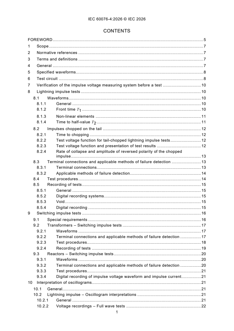
CONTENTS
FOREWORD . 5
1 Scope . 7
2 Normative references . 7
3 Terms and definitions . 7
4 General . 7
5 Specified waveforms. 8
6 Test circuit . 8
7 Verification of the impulse voltage measuring system before a test . 10
8 Lightning impulse tests . 10
8.1 Waveforms. 10
8.1.1 General . 10
8.1.2 Front time T . 10
8.1.3 Non-linear elements . 11
8.1.4 Time to half-value T . 11
8.2 Impulses chopped on the tail . 12
8.2.1 Time to chopping . 12
8.2.2 Test voltage function for tail-chopped lightning impulse tests . 12
8.2.3 Test voltage function and presentation of test results . 12
8.2.4 Rate of collapse and amplitude of reversed polarity of the chopped
impulse . 13
8.3 Terminal connections and applicable methods of failure detection . 13
8.3.1 Terminal connections . 13
8.3.2 Applicable methods of failure detection. 14
8.4 Test procedures . 14
8.5 Recording of tests . 15
8.5.1 General . 15
8.5.2 Digital recording systems . 15
8.5.3 Void . 15
8.5.4 Digital recording . 15
9 Switching impulse tests . 16
9.1 Special requirements . 16
9.2 Transformers – Switching impulse tests . 17
9.2.1 Waveforms . 17
9.2.2 Terminal connections and applicable methods of failure detection . 17
9.2.3 Test procedures. 18
9.2.4 Recording of tests . 19
9.3 Reactors – Switching impulse tests . 20
9.3.1 Waveforms . 20
9.3.2 Terminal connections and applicable methods of failure detection . 20
9.3.3 Test procedures. 21
9.3.4 Digital recording of impulse voltage waveform and impulse current . 21
10 Interpretation of oscillograms. 21
10.1 General . 21
10.2 Lightning impulse – Oscillogram interpretations . 21
10.2.1 General . 21
10.2.2 Voltage recordings – Full wave tests . 22
10.2.3 Current recordings – Full wave tests . 23
10.2.4 Voltage and current recordings – Chopped-wave tests . 23
10.3 Switching impulse – Oscillogram interpretations. 24
10.3.1 Voltage recordings . 24
10.3.2 Recordings of the impulse current . 24
11 Digital recording – Transfer function analysis . 25
12 Impulse testing report . 27
13 Impulse test circuits and terminal connections . 28
Annex A (informative) Principles of waveform control . 34
A.1 General . 34
A.2 High-impedance windings (L > 100 mH) . 34
t
A.3 Low-impedance windings (L < 20 mH) . 35
t
Annex B (informative) Typical oscillograms and digital recordings . 42
Annex C (informative) Examples of oscillograms with overshoots . 64
Bibliography . 71
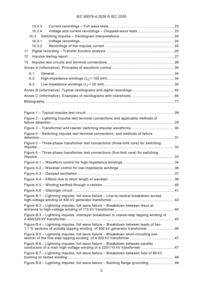
Figure 1 – Typical impulse test circuit . 28
Figure 2 – Lightning impulse test terminal connections and applicable methods of
failure detection . 29
Figure 3 – Transformer and reactor switching impulse waveforms. 30
Figure 4 – Switching impulse test terminal connections and methods of failure
detection . 31
Figure 5 – Three-phase transformer test connections (three-limb core) for switching
impulse . 32
Figure 6 – Three-phase transformer test connections (five-limb core) for switching
impulse . 33
Figure A.1 – Waveform control for high-impedance windings . 34
Figure A.2 – Wavetail control for low impedance windings . 36
Figure A.3 – Damped oscillation . 37
Figure A.4 – Effects due to short length of wavetail . 39
Figure A.5 – Winding earthed through a resistor . 40
Figure A.6 – Glaninger circuit . 41
Figure B.1 – Lightning impulse, full wave failure – Line-to-neutral breakdown across
high-voltage winding of 400 kV generator transformer . 43
Figure B.2 – Lightning impulse, full wave failure – Breakdown between discs at
entrance to high-voltage winding of 115 kV transformer . 44
Figure B.3 – Lightning impulse, interlayer breakdown in coarse-step tapping winding of
a 400/220 kV transformer . 45
Figure B.4 – Lightning impulse, full wave failure – Breakdown between leads of two
1,1 % sections of outside tapping winding of 400 kV generator transformer . 46
Figure B.5 – Lightning impulse, full wave failure – Breakdown short-circuiting one
section of the fine-step tapping winding of a 220 kV transformer . 47
Figure B.6 – Lightning impulse, full wave failure – Breakdown between parallel
conductors of a main high-voltage winding of a 220/110 kV transformer . 47
Figure B.7 – Lightning impulse, full wave failure – Breakdown between foils of 66 kV
bushing on tested winding. 48
Figure B.8 – Lightning impulse, full wave failure – Bushing flange grounding . 49
Figure B.9 – Lightning impulse, chopped-wave failure – Breakdown between turns in
the main high-voltage winding of a 115 kV transformer . 50
Figure B.10 – Lightning impulse, chopped-wave failure – Breakdown between turns in
a fine-step tapping winding of a 220 kV transformer . 51
Figure B.11 – Chopped lightning impulse – Impulses at different voltage levels with
identical times to chopping when testing a 115 kV transformer. 52
Figure B.12 – Chopped lightning impulse – Effects of differences in times to chopping
when testing a 220 kV transformer . 53
Figure B.13 – Full lightning impulse – Effect of non-linear resistors embodied in
neutral end on-load tap-changer of a transformer with separate windings . 54
Figure B.14 – Full lightning impulse – Effect of generator firing differences at different
voltage levels when testing a 400 kV transformer . 55
Figure B.15 – Switching impulse – Satisfactory test on a 400 kV three-phase generator
transformer . 56
Figure B.16 – Switching impulse – Breakdown by axial flashover of the main high-
voltage winding of a 525 kV single-phase, generator transformer . 57
Figure B.17 – Switching impulse – Satisfactory test on a 33 MVAr, 525 kV single-phase
reactor . 58
Figure B.18 – Full lightning impulse – Evaluation of a non-standard waveform –
Influence of in-built smoothing algorithms in digitizers . 59
Figure B.19 – Full lightning impulse – Non-standard waveform, superimposed
oscillations with >50 % amplitude and frequency <500 kHz . 59
Figure B.20 – Chopped lightning impulse – Non-standard chopped wave on a layer
type winding . 60
Figure B.21 – Lightning impulse – Comparison of the transfer function of a full wave
and a chopped wave . 61
Figure B.22 – Full lightning impulse – Test-circuit problem caused by a sparkover to
earth from a measuring cable. 62
Figure B.23 – Full lightning impulse – Failure digital recordings of a flashover between
tap leads of a tap changer and of a flashover between coarse and fine tapping
windings . 63
Figure C.1 – Lightning impulse oscillogram with an overshoot having a frequency
higher than 500 kHz (beta_k = ß′ = 7,35 %) – 3 phase transformer, 27,6 kV/208 V,
150 kVA, YNyn0 . 65
Figure C.2 – Lightning impulse oscillogram with an overshoot having a frequency
higher than 500 kHz (beta_k = ß′ = 10,3 %) – Transformer, 138 kV/13,8 kV, 33,3 MVA,
Dyn1 . 66
Figure C.3 – Lightning impulse oscillogram with an overshoot having a frequency
higher than 500 kHz (beta_k = ß′ = 14,2 %) – Transformer, 14,4 kV/120 V – 240 V,
50 kVA, 1 phase . 67
Figure C.4 – Lightning impulse oscillogram with an overshoot having a frequency less
than 500 kHz (beta_k = ß′ = 30,2 %) – Transformer, 34,5 kV/560 V, 3 600 kVA, 3 phase . 67
Figure C.5 – Lightning impulse oscillogram with an overshoot − ß′ = 6,80 % Single-
phase auto-transformer 267 MVA − 420 kV/247 kV/28 kV – LV terminal 247 kV . 68
Figure C.6 – Lightning impulse oscillogram with an overshoot − ß′ = 13,40 % Three-
phase auto-transformer 600 MVA − 345 kV/141,5 kV/13,8 kV – LV terminal 141,5 kV . 68
Figure C.7 – Lightning impulse oscillogram with an overshoot – ß′= 23,22 % Single-
phase auto-transformer 267 MVA – 420 kV/247 kV/28 kV – TV terminal 28 kV . 69
Figure C.8 – Example of lightning impulse oscillogram on bushing (capacitance test
object) with an overshoot ß′ = 3,92 %, without complex oscillations. 70
Table B.1 – Summary of examples illustrated in oscillograms and digital recordings . 42
Table C.1 – Summary of lightning impulse test oscillograms with overshoot . 64
INTERNATIONAL ELECTROTECHNICAL COMMISSION
____________
Power transformers -
Part 4: Lightning impulse and switching impulse tests
of power transformers and reactors
FOREWORD
1) The International Electrotechnical Commission (IEC) is a worldwide organization for standardization comprising
all national electrotechnical committees (IEC National Committees). The object of IEC is to promote international
co-operation on all questions concerning standardization in the electrical and electronic fields. To this end and
in addition to other activities, IEC publishes International Standards, Technical Specifications, Technical Reports,
Publicly Available Specifications (PAS) and Guides (hereafter referred to as “IEC Publication(s)”). Their
preparation is entrusted to technical committees; any IEC National Committee interested in the subject dealt with
can participate in this preparatory work. International, governmental and non-governmental organizations liaising
with the IEC also participate in this preparation. IEC collaborates closely with the International Organization for
Standardization (ISO) in accordance with conditions determined by agreement between the two organizations.
2) The formal decisions or agreements of IEC on technical matters express, as nearly as possible, an international
consensus of opinion on the relevant subjects since each technical committee has representation from all
interested IEC National Committees.
3) IEC Publications have the form of recommendations for international use and are accepted by IEC National
Committees in that sense. While all reasonable efforts are made to ensure that the technical content of IEC
Publications is accurate, IEC cannot be held responsible for the way in which they are used or for any
misinterpretation by any end user.
4) In order to promote international uniformity, IEC National Committees undertake to apply IEC Publications
transparently to the maximum extent possible in their national and regional publications. Any divergence between
any IEC Publication and the corresponding national or regional publication shall be clearly indicated in the latter.
5) IEC itself does not provide any attestation of conformity. Independent certification bodies provide conformity
assessment services and, in some areas, access to IEC marks of conformity. IEC is not responsible for any
services carried out by independent certification bodies.
6) All users should ensure that they have the latest edition of this publication.
7) No liability shall attach to IEC or its directors, employees, servants or agents including individual experts and
members of its technical committees and IEC National Committees for any personal injury, property damage or
other damage of any nature whatsoever, whether direct or indirect, or for costs (including legal fees) and
expenses arising out of the publication, use of, or reliance upon, this IEC Publication or any other IEC
Publications.
8) Attention is drawn to the Normative references cited in this publication. Use of the referenced publications is
indispensable for the correct application of this publication.
9) IEC draws attention to the possibility that the implementation of this document can involve the use of (a) patent(s).
IEC takes no position concerning the evidence, validity or applicability of any claimed patent rights in respect
thereof. As of the date of publication of this document, IEC had not received notice of (a) patent(s), which can
be required to implement this document. However, implementers are cautioned that this cannot represent the
latest information, which can be obtained from the patent database available at https://patents.iec.ch. IEC shall
not be held responsible for identifying any or all such patent rights.
IEC 60076-4 has been prepared by IEC technical committee 14: Power transformers. It is an
International Standard.
This second edition cancels and replaces the first edition published in 2002. This edition
constitutes a technical revision.
This edition includes the following significant technical changes with respect to the previous
edition:
a) lightning impulse tests in the presence of a relative overshoot value of 5 % or more (8.1.2).
The 2002 edition did not specified how to proceed when the overshoot exceeds 5 %. In this
revision, the testing laboratory is permitted to carry out the tests provided that the voltage
function calculation, as defined in IEC 60060-1:2010, is applied;
b) newly introduced test voltage for tail-chopped lightning impulse tests (8.2.2);
c) switching impulse tests on 3 phase transformers, test connections (see Figure 5 and
Figure 6);
d) new Glaninger circuit in Clause A.3 about low-impedance windings (L < 20 mH);
t
e) new Annex C with examples of oscillograms with peak voltage overshoot.
The text of this International Standard is based on the following documents:
Draft Report on voting
14/1204/FDIS 14/1208/RVD
Full information on the voting for its approval can be found in the report on voting indicated in
the above table.
The language used for the development of this International Standard is English.
This document was drafted in accordance with ISO/IEC Directives, Part 2, and developed in
accordance with ISO/IEC Directives, Part 1 and ISO/IEC Directives, IEC Supplement, available
at www.iec.ch/members_experts/refdocs. The main document types developed by IEC are
described in greater detail at www.iec.ch/publications.
A list of all parts in the IEC 60076 series, published under the general title Power transformers,
can be found on the IEC website.
The committee has decided that the contents of this document will remain unchanged until the
stability date indicated on the IEC website under webstore.iec.ch in the data related to the
specific document. At this date, the document will be
– reconfirmed,
– withdrawn, or
– revised.
1 Scope
This part of IEC 60076 applies to lightning and switching impulse tests on power transformers
and reactors.
Information is given on waveforms, test circuits including test connections, earthing practices,
failure detection methods, test procedures, measuring techniques and interpretation of results.
Where applicable, the test techniques are as described in IEC 60060-1 and IEC 60060-2.
2 Normative references
The following documents are referred to in the text in such a way that some or all of their content
constitutes requirements of this document. For dated references, only the edition cited applies.
For undated references, the latest edition of the referenced document (including any
amendments) applies.
IEC 60060-1:2010, High-voltage test techniques - Part 1: General definitions and test
requirements
IEC 60060-2, High-voltage test techniques - Part 2: Measuring systems
IEC 60076-3:2013, Power transformers - Part 3: Insulation levels, dielectric tests and external
clearances in air
IEC 60076-6, Power transformers - Part 6: Reactors
IEC 61083-1, Instruments and software used for measurements in high-voltage and high-
current tests - Part 1: Requirements for instruments for impulse tests
3 Terms and definitions
No terms and definitions are listed in this document.
ISO and IEC maintain terminology databases for use in standardization at the following
addresses:
– IEC Electropedia: available at https://www.electropedia.org/
– ISO Online browsing platform: available at https://www.iso.org/obp
4 General
This document is primarily based on the use of conventional impulse generators for both
lightning and switching impulse tests of transformers and reactors. The practice of switching
impulse generation with discharge of a separate capacitor into an intermediate or low-voltage
winding is also applicable. However, the method which employs an additional inductance in
series with the capacitor to provide slightly damped oscillations transferred into the high-voltage
winding is not applicable.
Alternative means of switching impulse generation or simulation such as DC current interruption
on an intermediate or low-voltage winding or the application of a part-period of power frequency
voltage are not discussed since these methods are not as generally applicable.
Different considerations in the choice of test circuits (terminal connections) for lightning and
switching impulse tests apply for transformers and reactors. On transformers, all terminals and
windings can be lightning impulse tested to specific and independent levels. In switching
impulse test, however, because of the induced voltage transferred, a specified test level can
only be obtained on one winding (see IEC 60076-3).
Whilst, on reactors, lightning impulse tests is similar to that on transformers, i.e., all terminals
can be tested separately, different considerations apply and different problems arise in
switching impulse tests. Hence, in this document, lightning impulse tests are covered by a
common text for both transformers and reactors whilst switching impulse test is dealt with
separately for the two types of equipment.
5 Specified waveforms
The voltage waveforms to be used normally during lightning and switching impulse tests of
transformers and reactors are given in IEC 60076-3, IEC 60076-6 and the methods for their
determination shall refer to IEC 60060-1.
6 Test circuit
The physical arrangement of test equipment, test object and measuring circuits can be divided
into three major circuits:
– the main circuit including the impulse generator, additional waveshaping components and
the test object;
– the voltage measuring circuit;
– the chopping circuit where applicable.
This basic arrangement is shown in Figure 1.
The following parameters influence the impulse waveform:
a) the effective capacitance C , and inductance of the test object, L ; C is constant for any
t t t
given design and any given waveform, L is also a constant for any given design.
t
The effective L , however, can be influenced by the terminal treatment. It varies between
t
the leakage inductance L for short-circuited terminals and L for open-circuited terminals.
s o
More details in this respect are given in 8.1 and 8.3 and in Annex A;
b) the generator capacitance C ;
g
c) waveshaping components, both internal and external to the generator, R , R , R , C (plus,
si se p L
where applicable, the impedance of a voltage divider Z );
d) the stray inductance and capacitance of the generator and the complete test circuit;
e) chopping equipment, where applicable;
f) non-linear elements in the transformer, which can cause differences between impulses at
different voltage levels.
The front time T is determined mainly by combination of the effective surge capacitance of the
test object, including C , and the generator internal and external series resistances.
L
The time to half-value T is, for lightning impulses, primarily determined by the generator
capacitance, the inductance of the test object and the generator discharge resistance or any
other parallel resistance. However, there are cases, for example, windings of extremely low
inductance, where the series resistance will have a significant effect also on the wavetail.
For switching impulses, other parameters apply; these are dealt with in Clause 9.
The test equipment used in lightning and switching impulse applications is basically the same.
Differences are in details only, such as values of resistors and capacitors (and the terminal
connections of the test object).
To meet the distinct waveform requirements for lightning and switching impulses, due
consideration shall be given to the selection of the impulse generator parameters, including
capacitance, series resistance and discharge (parallel) resistance. When generating switching
impulses, large series resistors, load capacitors, or both can be required, which can significantly
reduce efficiency.
While the output voltage of the impulse generator is determined by the test levels of the
windings with respect to their highest voltage for equipment U for the test object, the required
m
energy storage capability is essentially dependent on the inherent impedances of the test
object.
A brief explanation of the principles of waveform control is given in Annex A.
The arrangement of the test plant, test object and the interconnecting cables, earthing strips,
and other equipment is limited by the space in the test room and, particularly, the proximity
effect of any structures. During impulse tests, zero potential cannot be assumed throughout the
earthing systems due to the high values and rates of change of impulse currents and voltages
and the finite impedances involved. Therefore, the selection of a proper reference earth is
important.
The current return path between the test object and the impulse generator should be of low
impedance. It is good practice to firmly connect this current return path to the general earth
system of the test room, preferably close to the test object. This point of connection should be
used as reference earth and to attain good earthing of the test object it should be connected to
the reference earth by one or several conductors of low impedance (see IEC 60060-2).
The voltage measuring circuit, which is a separate loop of the test object carrying only the
measuring current and not any major portion of the impulse current flowing through the windings
under test, should also be effectively connected to the same reference earth.
In switching impulse tests, since the rates of change of the impulse voltages and currents are
much reduced compared with those in a lightning impulse test and no chopping circuit is
involved, the problems of potential gradients around the test circuit and with respect to the
reference earth are less critical. Nevertheless, it is suggested that, as a precaution, the same
earthing practices should be followed as used for lightning impulse tests.
Electromagnetic interference:
– Power transformers are more and more fitted with control and protection devices, which are
sensitive in regard of overvoltage, caused by (fast) transients.
– Potential differences, caused by special groundings at lightning and switching impulse tests.
The different grounding of the control-and protection device (in regard of safety) can
damage electronic parts.
Examples of affected devices:
– Mainly large transformers fitted with (computerized) condition monitoring systems.
– Cooling equipment (fans, pumps) is driven in dependence of transformer load and
transformer noise and controlled by electronic devices, etc.
During impulse tests, it is recommended to disconnect all electric and electronic equipment
installed on the transformer.
7 Verification of the impulse voltage measuring system before a test
The impulse voltage measuring system shall be verified in accordance with IEC 60060 (all
parts). Before a test, an overall check of the test circuit and the measuring system can be
performed at a voltage lower than the reduced test voltage level. In this check, the voltage can
be determined by means of a sphere gap or by comparative measurement with another
approved device. When using a sphere gap, it should be recognized that this is only a check
and does not replace the periodically performed calibration of the approved measuring system.
After any check has been made, it is essential that neither the measuring nor the test circuit is
altered except for the removal of any devices for checking.
Information on types of voltage dividers, their applications, accuracy, calibration and checking
shall be as given in IEC 60060-2.
8 Lightning impulse tests
8.1 Waveforms
8.1.1 General
The values of waveform specified cannot always be obtainable. In the impulse tests of large
power transformers and reactors, of either low winding inductance or high surge capacitance
or windings with low ohmic resistance, or both, wider tolerances can have to be accepted
(Table B.1).
8.1.2 Front time T
The surge capacitance of the transformer under test being constant, the series resistance shall
have to be reduced in an attempt to obtain the correct front time T or rate of rise, but the
reduction should not be to the extent that oscillations on the crest of the voltage wave become
excessive. If achieving a short front time (preferably within the specified limits) is considered
desirable, oscillations, overshoots, or both can have to be accepted. In such an event, a
compromise between the extent of allowable oscillations and the obtainable front time is
necessary. In general, the test circuit should be arranged in such way that overshoot and
oscillation are minimal.
Examples of oscillograms having overshoot are summarized in Table C.1 and shown in
Figure C.1, Figure C.2, Figure C.3, Figure C.4, Figure C.5, Figure C.6, Figure C.7, and
Figure C.8.
If the relative overshoot, ß′, exceeds 5 %, IEC 60076-3:2013, 13.2.1 gives options:
Option 1 – Adjust T
T can be increased; however if it exceeds 1,56 µs, a chopped wave is required to ensure high-
frequency content:
• For transformers with U ≤ 800 kV, T limit is 2,5 µs,
m 1
• For transformers with U > 800 kV, T > 2,5 µs may be accepted, subject of agreement
m 1
between purchaser and manufacturer.
Option 2 – Accept the overshoot
If the relative overshoot (ß′) exceeds 5 %, testing can proceed provided that the lightning
impulse parameters are calculated with the test voltage function in accordance with
IEC 60060-1:2010, Annex B.
NOTE When ß′ is large and the overshoot contains high-frequency components (> 500 kHz), the test voltage
function can reduce the test voltage value (U ) significantly below the peak value U of the recorded curve. This
t e
discrepancy can impose higher electrical stress on the insulation and increase the risk of dielectric breakdown.
For transformer testing, manual evaluation of the lightning impulse test voltage is generally
unreliable. If the manufacturer does not have the software that implement the IEC 60060-1 test
voltage function, the purchaser shall be informed at the quotation stage.
8.1.3 Non-linear elements
In some power transformers, the active parts are protected by non-linear surge arresters. When
lightning-impulse tests are applied, these devices can modify the voltage waveform; the shape
varies with the amplitude of the impulse.
According to IEC 60076-3, the test sequence shall consist of:
– three reference impulses;
– three 100 % full wave impulses;
– three comparison impulses,
with at least one of the reference impulses being lower than the arrester’s operating (knee)
voltage.
NOTE Sequence of reference impulses (see IEC 60076-3):
1) between 50 % and 60 % of the full wave test voltage;
2) between 60 % and 75 % of the full wave test voltage;
3) between 75 % and 90 % of the full wave test voltage.
8.1.4 Time to half-value T
For large power transformers and particularly the intermediate and low-voltage windings
thereof, the virtual time to half-value T cannot be achievable within the value set by the
tolerance. The inductance of such windings can be so low that the resulting waveform is
oscillatory. This problem can be solved to some extent by the use of large capacitance within
the generator, by parallel stage operation, by adjustment of the series resistor or by specific
test connections of the terminals of windings not under test or, in addition, of the non-tested
terminals of windings under test.
If lightning impulse tests are carried out on phase-terminals of a delta-winding, the not-tested
terminals of that winding can be resistance earthed.
If the neutral of a star-connected winding is tested, the phase-terminals can be resistance
earthed.
If the phase terminals of a star-connected winding are tested, the neutral-terminal shall be
solidly grounded or grounded through a low-ohmic shunt.
When resistance earthing of any non-tested line terminal is employed, it is necessary to ensure
that the voltage to earth appearing on any non-tested terminal does not exceed
– 75 % of the rated lightning withstand voltage of that terminal for star-connected windings;
– 50 % of the rated lightning withstand voltage of that terminal for delta-connected windings
(because of the undershoot voltages to earth on the delta terminals – see also 8.4).
When the waveform is oscillatory due to extremely low inductance or small impulse generator
capacitance, or both, the amplitude of the undershoot should not exceed 50 % of the test
voltage. With this limitation, guidance for selecting impulse generator capacitance and adjusting
waveforms is given in Annex A.
8.2 Impulses chopped on the tail
8.2.1 Time to chopping
Different times to chopping T (as defined in IEC 60060-2), will result in different stresses
c
(voltage and duration) in different parts of the winding(s) depending on the winding construction
and arrangement employed. Hence, it is not possible to state a time to chopping which is the
most onerous either in general or for any particular transformer or reactor. The time to chopping
should be between 3 µs and 6 µs. A time, between 2 µs and 6 µs can be accepted, provided
that the peak value of the lightning impulse wave is achieved before the chop, as required by
IEC 60076-3:2013, 13.3.1.
Oscillograms or digital recordings of chopped waves, are only comparable up to the times to
chopping, except in the case where the chopping time is reasonably identical (8.2.4).
8.2.2 Test voltage function for tail-chopped lightning impulse tests
a) Procedure (liquid-immersed and dry-type transformers)
• Apply a chopped-wave impulse at the required test level.
The recorded curve provides the peak value U . If the system does not display U
e e
directly, perform a graphic evaluation of U from the oscillogram.
e
• The calculated test voltage curve, obtained using a software that incorporates
IEC 60060-1:2010 requirements, displays the peak value U .
t
• If U differs from the expected value (110 % for liquid-immersed transformers or 100 %
t
for dry-type transformers), proceed with the voltage reduction ratio method (IEEE Std
4™-2013).
b) Voltage reduction ratio method (liquid-immersed transformers)
• Apply a reduced full wave (RFW) and record U .
e
• Read the corresponding U provided by the measuring system.
t
• Determine the reduction ratio:
R = U / U
v t e
• Apply the chopped-wave impulse test at 110 % level.
• Evaluate the full-voltage chopped wave using:
U' = R x U'
t v e
• Front time reference: use the front time value measured during the RFW test for all
subsequent evaluations.
c) Voltage reduction ratio method (dry-type transformers)
• Follow the same sequence, but perform the chopped wave test at 100 % of the full wave
level instead of 110 %.
• All other steps (RFW application, ratio calculation, front-time reuse) remain identical.
8.2.3 Test voltage function and presentation of test results
When the test voltage function is implemented, the following test results shall be displayed:
U is the peak value of the test voltage curve.
t
ß′ is the relative overshoot.
Optionally, the following may also be displayed:
U is the peak value of the recorded curve.
e
8.2.4 Rate of collapse and amplitude of reversed polarity of the chopped impulse
The characteristic events during chopping are largely dependent on the geometrical
arrangement of the chopping circuit involved and on the impedance of the chopping circuit and
of the test object, all of which determine both the rate of collapse and the amplitude of the
undershoot.
In IEC 60076-3, the undershoot has been limited to 30 % of the amplitude of the chopped
impulse. This, in fact, represents a guideline for the arrangement of the chopping circuit and
can entail the introduction of additional impedance Z in this circuit to meet the limit (see
c
Figure 1).
The chopping loop, however, should be as small as possible to obtain the highest rate of
collapse, but the undershoot should be limited to less than, or equal to 30 %. On multiple layer
windings, the layer impedance can damp the collapse normally to the extent that it does not
oscillate around zero (see Figure B.20).
The recommendation in IEC 60076-3 to use a triggered type chopping gap is made because of
its advantage in obtaining consistency of the time to chopping, thereby facilitating the
comparison of oscillograph or digital recordings not only before but also after chopping.
The latter part will only be comparable for reasonably identical chopping times.
8.3 Terminal connections and applicable methods of failure detection
8.3.1 Terminal connections
It is essential that the terminal connections of the test object and the earthing practices
employed relate to the method of failure detection adopted.
Connections for impulse tests are detailed in IEC 60076-3 for transformers and in IEC 60076-6
for reactors. Normally the non-tested terminals of the phase winding under test are earthed and
the non-tested phase windings are shorted and earthed. Howev
...
IEC 60076-4 ®
Edition 2.0 2026-07
INTERNATIONAL
STANDARD
REDLINE VERSION
Power transformers -
Part 4: Guide to the Lightning impulse and switching impulse testing – tests of
power transformers and reactors
ICS 29.180 ISBN 978-2-8327-1383-9
All rights reserved. Unless otherwise specified, no part of this publication may be reproduced or utilized in any form or
by any means, electronic or mechanical, including photocopying and microfilm, without permission in writing from either
IEC or IEC's member National Committee in the country of the requester. If you have any questions about IEC copyright
or have an enquiry about obtaining additional rights to this publication, please contact the address below or your local
IEC member National Committee for further information.
IEC Secretariat Tel.: +41 22 919 02 11
3, rue de Varembé info@iec.ch
CH-1211 Geneva 20 www.iec.ch
Switzerland
About the IEC
The International Electrotechnical Commission (IEC) is the leading global organization that prepares and publishes
International Standards for all electrical, electronic and related technologies.
About IEC publications
The technical content of IEC publications is kept under constant review by the IEC. Please make sure that you have the
latest edition, a corrigendum or an amendment might have been published.
IEC publications search - IEC Products & Services Portal - products.iec.ch
webstore.iec.ch/advsearchform Discover our powerful search engine and read freely all the
The advanced search enables to find IEC publications by a publications previews, graphical symbols and the glossary.
variety of criteria (reference number, text, technical With a subscription you will always have access to up to date
committee, …). It also gives information on projects, content tailored to your needs.
replaced and withdrawn publications.
Electropedia - www.electropedia.org
IEC Just Published - webstore.iec.ch/justpublished The world's leading online dictionary on electrotechnology,
Stay up to date on all new IEC publications. Just Published containing more than 22 500 terminological entries in English
details all new publications released. Available online and and French, with equivalent terms in 25 additional languages.
once a month by email. Also known as the International Electrotechnical Vocabulary
(IEV) online.
IEC Customer Service Centre - webstore.iec.ch/csc
If you wish to give us your feedback on this publication or
need further assistance, please contact the Customer
Service Centre: sales@iec.ch.
CONTENTS
FOREWORD . 5
1 Scope . 7
2 Normative references . 7
3 Terms and definitions . 7
4 General . 8
5 Specified waveforms. 8
6 Test circuit . 8
7 Calibration Verification of the impulse voltage measuring system before a test . 10
8 Lightning impulse tests . 10
8.1 WaveshapesWaveforms . 10
8.1.1 General . 10
8.1.2 Front time T . 10
8.1.3 Non-linear elements . 11
8.1.4 Time to half-value T . 11
8.2 Impulses chopped on the tail . 12
8.2.1 Time to chopping . 12
8.2.2 Test voltage function for tail-chopped lightning impulse tests . 12
8.2.3 Test voltage function and presentation of test results . 13
8.2.4 Rate of collapse and amplitude of reversed polarity of the chopped
impulse . 13
8.3 Terminal connections and applicable methods of failure detection . 14
8.3.1 Terminal connections . 14
8.3.2 Applicable methods of failure detection. 14
8.4 Test procedures . 15
8.5 Recording of tests . 15
8.5.1 General . 15
8.5.2 Analogue and Digital recording systems . 15
8.5.3 Analogue recording of waveshapes Void . 16
8.5.4 Digital recording of waveshapes . 17
9 Switching impulse tests . 18
9.1 Special requirements . 18
9.2 Transformers – Switching impulse tests . 18
9.2.1 Waveforms . 18
9.2.2 Terminal connections and applicable methods of failure detection . 19
9.2.3 Test procedures. 20
9.2.4 Recording of tests . 21
9.3 Reactors – Switching impulse tests . 23
9.3.1 WaveshapesWaveforms . 23
9.3.2 Terminal connections and applicable methods of failure detection . 24
9.3.3 Test procedures. 24
9.3.4 Analogue and Digital recording of impulse voltage waveshape
waveform and impulse response current . 24
10 Interpretation of oscillograms or digital recordings . 24
10.1 General . 24
10.2 Lightning impulse – Oscillogram interpretations . 25
10.2.1 General . 25
10.2.2 Voltage recordings – Full wave tests . 25
10.2.3 Current recordings – Full wave tests . 26
10.2.4 Voltage and current recordings – Chopped-wave tests . 27
10.3 Switching impulse – Oscillogram interpretations. 27
10.3.1 Voltage recordings . 27
10.3.2 Recordings of the impulse response current . 28
11 Digital processing recording, including – Transfer function analysis . 28
12 Impulse testing report . 30
13 Impulse test circuits and terminal connections . 31
Annex A (informative) Principles of waveshape waveform control . 38
A.1 General . 38
A.2 High-impedance windings (L > 100 mH) . 39
t
A.3 Low-impedance windings (L < 20 mH) . 41
t
Annex B (informative) Typical oscillograms and digital recordings . 47
Annex C (informative) Examples of oscillograms with overshoots . 71
Bibliography . 78
Figure 1 – Typical impulse test circuit . 31
Figure 2 – Lightning impulse test terminal connections and applicable methods of
failure detection . 32
Figure 3 – Transformer and reactor switching impulse waveshapes .
Figure 3 – Transformer and reactor switching impulse waveforms. 34
Figure 4 – Switching impulse test terminal connections and methods of failure
detection . 35
Figure 5 – Three-phase transformer test connections (three-limb core) for switching
impulse . 36
Figure 6 – Three-phase transformer test connections (five-limb core) for switching
impulse . 37
Figure A.1 – Waveshape Waveform control for high-impedance windings . 39
Figure A.2 – Wavetail control for low impedance windings . 41
Figure A.3 – Damped oscillation . 42
Figure A.4 – Effects due to short length of wavetail . 44
Figure A.5 – Winding earthed through a resistor . 45
Figure A.6 – Resistance earthing of low-impedance windings .
Figure A.6 – Glaninger circuit . 46
Figure B.1 – Lightning impulse, full wave failure – Line-to-neutral breakdown across
high-voltage winding of 400 kV generator transformer . 49
Figure B.2 – Lightning impulse, full wave failure – Breakdown between discs at
entrance to high-voltage winding of 115 kV transformer . 50
Figure B.3 – Lightning impulse, interlayer breakdown in coarse-step tapping winding of
a 400/220 kV transformer . 51
Figure B.4 – Lightning impulse, full wave failure – Breakdown between leads of two
1,1 % sections of outside tapping winding of 400 kV generator transformer . 52
Figure B.5 – Lightning impulse, full wave failure – Breakdown short-circuiting one
section of the fine-step tapping winding of a 220 kV transformer . 53
Figure B.6 – Lightning impulse, full wave failure – Breakdown between parallel
conductors of a main high-voltage winding of a 220/110 kV transformer . 53
Figure B.7 – Lightning impulse, full wave failure – Breakdown between foils of 66 kV
bushing on tested winding. 54
Figure B.8 – Lightning impulse, full wave failure – Bushing flange grounding . 55
Figure B.9 – Lightning impulse, chopped-wave failure – Breakdown between turns in
the main high-voltage winding of a 115 kV transformer . 56
Figure B.10 – Lightning impulse, chopped-wave failure – Breakdown between turns in
a fine-step tapping winding of a 220 kV transformer . 57
Figure B.11 – Chopped lightning impulse – Impulses at different voltage levels with
identical times to chopping when testing a 115 kV transformer. 58
Figure B.12 – Chopped lightning impulse – Effects of differences in times to chopping
when testing a 220 kV transformer . 59
Figure B.13 – Full lightning impulse – Effect of non-linear resistors embodied in
neutral end on-load tap-changer of a transformer with separate windings . 60
Figure B.14 – Full lightning impulse – Effect of generator firing differences at different
voltage levels when testing a 400 kV transformer . 61
Figure B.15 – Switching impulse – Satisfactory test on a 400 kV three-phase generator
transformer . 62
Figure B.16 – Switching impulse – Breakdown by axial flashover of the main high-
voltage winding of a 525 kV single-phase, generator transformer . 63
Figure B.17 – Switching impulse – Satisfactory test on a 33 MVAr, 525 kV single-phase
reactor . 64
Figure B.18 – Full lightning impulse – Evaluation of a non-standard waveform –
Influence of in-built smoothing algorithms in digitizers . 65
Figure B.19 – Full lightning impulse – Non-standard waveform, superimposed
oscillations with >50 % amplitude and frequency <500 kHz . 65
Figure B.20 – Chopped lightning impulse – Non-standard chopped wave on a layer
type winding . 66
Figure B.21 – Full lightning impulse – Non-standard waveshape, comparison of non-
standard waveshapes by digitizers of different make from the same recording .
Figure B.21 – Lightning impulse – Comparison of the transfer function of a full wave
and a chopped wave . 68
Figure B.22 – Full lightning impulse – Test-circuit problem caused by a sparkover to
earth from a measuring cable. 69
Figure B.23 – Full lightning impulse – Failure digital recordings of a flashover between
tap leads of a tap changer and of a flashover between coarse and fine tapping
windings . 70
Figure C.1 – Lightning impulse oscillogram with an overshoot having a frequency
higher than 500 kHz (beta_k = ß′ = 7,35 %) – 3 phase transformer, 27,6 kV/208 V,
150 kVA, YNyn0 . 72
Figure C.2 – Lightning impulse oscillogram with an overshoot having a frequency
higher than 500 kHz (beta_k = ß′ = 10,3 %) – Transformer, 138 kV/13,8 kV, 33,3 MVA,
Dyn1 . 73
Figure C.3 – Lightning impulse oscillogram with an overshoot having a frequency
higher than 500 kHz (beta_k = ß′ = 14,2 %) – Transformer, 14,4 kV/120 V – 240 V,
50 kVA, 1 phase . 74
Figure C.4 – Lightning impulse oscillogram with an overshoot having a frequency less
than 500 kHz (beta_k = ß′ = 30,2 %) – Transformer, 34,5 kV/560 V, 3 600 kVA, 3 phase . 74
Figure C.5 – Lightning impulse oscillogram with an overshoot − ß′ = 6,80 % Single-
phase auto-transformer 267 MVA − 420 kV/247 kV/28 kV – LV terminal 247 kV . 75
Figure C.6 – Lightning impulse oscillogram with an overshoot − ß′ = 13,40 % Three-
phase auto-transformer 600 MVA − 345 kV/141,5 kV/13,8 kV – LV terminal 141,5 kV . 75
Figure C.7 – Lightning impulse oscillogram with an overshoot – ß′= 23,22 % Single-
phase auto-transformer 267 MVA – 420 kV/247 kV/28 kV – TV terminal 28 kV . 76
Figure C.8 – Example of lightning impulse oscillogram on bushing (capacitance test
object) with an overshoot ß′ = 3,92 %, without complex oscillations. 77
Table B.1 – Summary of examples illustrated in oscillograms and digital recordings . 47
Table C.1 – Summary of lightning impulse test oscillograms with overshoot . 71
INTERNATIONAL ELECTROTECHNICAL COMMISSION
____________
Power transformers -
Part 4: Guide to the Lightning impulse and switching impulse testing –
tests of power transformers and reactors
FOREWORD
1) The International Electrotechnical Commission (IEC) is a worldwide organization for standardization comprising
all national electrotechnical committees (IEC National Committees). The object of IEC is to promote international
co-operation on all questions concerning standardization in the electrical and electronic fields. To this end and
in addition to other activities, IEC publishes International Standards, Technical Specifications, Technical Reports,
Publicly Available Specifications (PAS) and Guides (hereafter referred to as “IEC Publication(s)”). Their
preparation is entrusted to technical committees; any IEC National Committee interested in the subject dealt with
can participate in this preparatory work. International, governmental and non-governmental organizations liaising
with the IEC also participate in this preparation. IEC collaborates closely with the International Organization for
Standardization (ISO) in accordance with conditions determined by agreement between the two organizations.
2) The formal decisions or agreements of IEC on technical matters express, as nearly as possible, an international
consensus of opinion on the relevant subjects since each technical committee has representation from all
interested IEC National Committees.
3) IEC Publications have the form of recommendations for international use and are accepted by IEC National
Committees in that sense. While all reasonable efforts are made to ensure that the technical content of IEC
Publications is accurate, IEC cannot be held responsible for the way in which they are used or for any
misinterpretation by any end user.
4) In order to promote international uniformity, IEC National Committees undertake to apply IEC Publications
transparently to the maximum extent possible in their national and regional publications. Any divergence between
any IEC Publication and the corresponding national or regional publication shall be clearly indicated in the latter.
5) IEC itself does not provide any attestation of conformity. Independent certification bodies provide conformity
assessment services and, in some areas, access to IEC marks of conformity. IEC is not responsible for any
services carried out by independent certification bodies.
6) All users should ensure that they have the latest edition of this publication.
7) No liability shall attach to IEC or its directors, employees, servants or agents including individual experts and
members of its technical committees and IEC National Committees for any personal injury, property damage or
other damage of any nature whatsoever, whether direct or indirect, or for costs (including legal fees) and
expenses arising out of the publication, use of, or reliance upon, this IEC Publication or any other IEC
Publications.
8) Attention is drawn to the Normative references cited in this publication. Use of the referenced publications is
indispensable for the correct application of this publication.
9) IEC draws attention to the possibility that the implementation of this document can involve the use of (a) patent(s).
IEC takes no position concerning the evidence, validity or applicability of any claimed patent rights in respect
thereof. As of the date of publication of this document, IEC had not received notice of (a) patent(s), which can
be required to implement this document. However, implementers are cautioned that this cannot represent the
latest information, which can be obtained from the patent database available at https://patents.iec.ch. IEC shall
not be held responsible for identifying any or all such patent rights.
This redline version of the official IEC Standard allows the user to identify the changes made
to the previous edition IEC 60076-4:2002. A vertical bar appears in the margin wherever a
change has been made. Additions are in green text, deletions are in strikethrough red text.
IEC 60076-4 has been prepared by IEC technical committee 14: Power transformers. It is an
International Standard.
This second edition cancels and replaces the first edition published in 2002. This edition
constitutes a technical revision.
This edition includes the following significant technical changes with respect to the previous
edition:
a) lightning impulse tests in the presence of a relative overshoot value of 5 % or more (8.1.2).
The 2002 edition did not specified how to proceed when the overshoot exceeds 5 %. In this
revision, the testing laboratory is permitted to carry out the tests provided that the voltage
function calculation, as defined in IEC 60060-1:2010, is applied;
b) newly introduced test voltage for tail-chopped lightning impulse tests (8.2.2);
c) switching impulse tests on 3 phase transformers, test connections (see Figure 5 and
Figure 6);
d) new Glaninger circuit in Clause A.3 about low-impedance windings (L < 20 mH);
t
e) new Annex C with examples of oscillograms with peak voltage overshoot.
The text of this International Standard is based on the following documents:
Draft Report on voting
14/1204/FDIS 14/1208/RVD
Full information on the voting for its approval can be found in the report on voting indicated in
the above table.
The language used for the development of this International Standard is English.
This document was drafted in accordance with ISO/IEC Directives, Part 2, and developed in
accordance with ISO/IEC Directives, Part 1 and ISO/IEC Directives, IEC Supplement, available
at www.iec.ch/members_experts/refdocs. The main document types developed by IEC are
described in greater detail at www.iec.ch/publications.
A list of all parts in the IEC 60076 series, published under the general title Power transformers,
can be found on the IEC website.
The committee has decided that the contents of this document will remain unchanged until the
stability date indicated on the IEC website under webstore.iec.ch in the data related to the
specific document. At this date, the document will be
– reconfirmed,
– withdrawn, or
– revised.
1 Scope
This part of IEC 60076 gives guidance and explanatory comments on the existing procedures for
lightning and switching impulse testing of power transformers to supplement the requirements of
IEC 60076-3. It is also generally applicable to the testing of reactors (see IEC 60289), modifications
to power transformer procedures being indicated where required.
This part of IEC 60076 applies to lightning and switching impulse tests on power transformers
and reactors.
Information is given on waveshapes waveforms, test circuits including test connections,
earthing practices, failure detection methods, test procedures, measuring techniques and
interpretation of results.
Where applicable, the test techniques are as recommended described in IEC 60060-1 and
IEC 60060-2.
2 Normative references
The following documents are referred to in the text in such a way that some or all of their content
constitutes requirements of this document. For dated references, only the edition cited applies.
For undated references, the latest edition of the referenced document (including any
amendments) applies.
IEC 60060-1:2010, High-voltage test techniques - Part 1: General definitions and test
requirements
IEC 60060-2, High-voltage test techniques - Part 2: Measuring systems
IEC 60076-3:2013, Power transformers - Part 3: Insulation levels, dielectric tests and external
clearances in air
IEC 60289, Reactors
IEC 60076-6, Power transformers - Part 6: Reactors
IEC 61083-1, Instruments and software used for measurements in high-voltage impulse and
high-current tests - Part 1: Requirements for instruments for impulse tests
IEC 61083-2, Digital recorders for measurements in high-voltage impulse tests – Part 2:
Evaluation of software used for the determination of the parameters of impulse waveforms
3 Terms and definitions
No terms and definitions are listed in this document.
ISO and IEC maintain terminology databases for use in standardization at the following
addresses:
– IEC Electropedia: available at https://www.electropedia.org/
– ISO Online browsing platform: available at https://www.iso.org/obp
4 General
This document is primarily based on the use of conventional impulse generators for both
lightning and switching impulse tests of transformers and reactors. The practice of switching
impulse generation with discharge of a separate capacitor into an intermediate or low-voltage
winding is also applicable. However, the method which employs an additional inductance in
series with the capacitor to provide slightly damped oscillations transferred into the high-voltage
winding is not applicable.
Alternative means of switching impulse generation or simulation such as DC current interruption
on an intermediate or low-voltage winding or the application of a part-period of power frequency
voltage are not discussed since these methods are not as generally applicable.
Different considerations in the choice of test circuits (terminal connections) for lightning and
switching impulse tests apply for transformers and reactors. On transformers, all terminals and
windings can be lightning impulse tested to specific and independent levels. In switching
impulse test, however, because of the magnetically induced voltage transferred voltage, a
specified test level may can only be obtained on one winding (see IEC 60076-3).
Whilst, on reactors, lightning impulse tests is similar to that on transformers, i.e., all terminals
can be tested separately, different considerations apply and different problems arise in
switching impulse tests. Hence, in this document, lightning impulse tests are covered by a
common text for both transformers and reactors whilst switching impulse test is dealt with
separately for the two types of equipment.
5 Specified waveshapes waveforms
The voltage waveshapes waveforms to be used normally during lightning and switching impulse
tests of transformers and reactors are given in IEC 60076-3, IEC 60076-6 and the methods for
their determination are given in shall refer to IEC 60060-1.
6 Test circuit
The physical arrangement of test equipment, test object and measuring circuits can be divided
into three major circuits:
– the main circuit including the impulse generator, additional waveshaping components and
the test object;
– the voltage measuring circuit;
– the chopping circuit where applicable.
This basic arrangement is shown in Figure 1.
The following parameters influence the impulse waveshape waveform:
a) the effective capacitance C , and inductance of the test object, L ; C is constant for any
t t t
given design and any given waveshape waveform, L is also a constant for any given design.
t
The effective L , however, may can be influenced by the terminal treatment. It varies
t
between the leakage inductance L for short-circuited terminals and L for open-circuited
s o
terminals. More details in this respect are given in 8.1 and 8.3 and in Annex A;
b) the generator capacitance C ;
g
c) waveshaping components, both internal and external to the generator, R , R , R , C (plus,
si se p L
where applicable, the impedance of a voltage divider Z );
d) the stray inductance and capacitance of the generator and the complete test circuit;
e) chopping equipment, where applicable;
f) non-linear elements in the transformer, which can cause differences between impulses at
different voltage levels.
The front time T is determined mainly by combination of the effective surge capacitance of the
test object, including C , and the generator internal and external series resistances.
L
is, for lightning impulses, primarily determined by the generator
The time to half-value T
capacitance, the inductance of the test object and the generator discharge resistance or any
other parallel resistance. However, there are cases, for example, windings of extremely low
inductance, where the series resistance will have a significant effect also on the wavetail.
For switching impulses, other parameters apply; these are dealt with in Clause 9.
The test equipment used in lightning and switching impulse applications is basically the same.
Differences are in details only, such as values of resistors and capacitors (and the terminal
connections of the test object).
To meet the different distinct waveform requirements of the waveshape for lightning and
switching impulses, due consideration has to shall be given to the selection of the impulse
generator parameters, including capacitance, series resistance and discharge (parallel)
resistance. For switching impulses, large values of series resistors and/or load capacitors may
be necessary, which will result in significant reduction of the efficiency. When generating
switching impulses, large series resistors, load capacitors, or both can be required, which can
significantly reduce efficiency.
While the output voltage of the impulse generator is determined by the test levels of the
windings with respect to their highest voltage for equipment U for the test object, the required
m
energy storage capability is essentially dependent on the inherent impedances of the test
object.
A brief explanation of the principles of waveshape waveform control is given in Annex A.
The arrangement of the test plant, test object and the interconnecting cables, earthing strips,
and other equipment is limited by the space in the test room and, particularly, the proximity
effect of any structures. During impulse tests, zero potential cannot be assumed throughout the
earthing systems due to the high values and rates of change of impulse currents and voltages
and the finite impedances involved. Therefore, the selection of a proper reference earth is
important.
The current return path between the test object and the impulse generator should be of low
impedance. It is good practice to firmly connect this current return path to the general earth
system of the test room, preferably close to the test object. This point of connection should be
used as reference earth and to attain good earthing of the test object it should be connected to
the reference earth by one or several conductors of low impedance (see IEC 60060-2).
The voltage measuring circuit, which is a separate loop of the test object carrying only the
measuring current and not any major portion of the impulse current flowing through the windings
under test, should also be effectively connected to the same reference earth.
In switching impulse tests, since the rates of change of the impulse voltages and currents are
much reduced compared with those in a lightning impulse test and no chopping circuit is
involved, the problems of potential gradients around the test circuit and with respect to the
reference earth are less critical. Nevertheless, it is suggested that, as a precaution, the same
earthing practices should be followed as used for lightning impulse tests.
Electromagnetic interference:
– Power transformers are more and more fitted with control and protection devices, which are
sensitive in regard of overvoltage, caused by (fast) transients.
– Potential differences, caused by special groundings at lightning and switching impulse tests.
The different grounding of the control-and protection device (in regard of safety) can
damage electronic parts.
Examples of affected devices:
– Mainly large transformers fitted with (computerized) condition monitoring systems.
– Cooling equipment (fans, pumps) is driven in dependence of transformer load and
transformer noise and controlled by electronic devices, etc.
During impulse tests, it is recommended to disconnect all electric and electronic equipment
installed on the transformer.
7 Calibration Verification of the impulse voltage measuring system before a
test
It is not the intention of this standard to give any recommendation on measuring systems or
their calibration but, of course, the apparatus which is used should be approved in accordance
with IEC 60060. The impulse voltage measuring system shall be verified in accordance with
IEC 60060 (all parts). Before a test, an overall check of the test circuit and the measuring
system may can be performed at a voltage lower than the reduced test voltage level. In this
check, the voltage may can be determined by means of a sphere gap or by comparative
measurement with another approved device. When using a sphere gap, it should be recognized
that this is only a check and does not replace the periodically performed calibration of the
approved measuring system. After any check has been made, it is essential that neither the
measuring nor the test circuit is altered except for the removal of any devices for checking.
Information on types of voltage dividers, their applications, accuracy, calibration and checking
is shall be as given in IEC 60060-2.
8 Lightning impulse tests
8.1 WaveshapesWaveforms
8.1.1 General
The values of waveshape waveform specified may not cannot always be obtainable. In the
impulse tests of large power transformers and reactors, of either low winding inductance or high
surge capacitance or windings with low ohmic resistance, or both, wider tolerances may can
have to be accepted (Table B.1).
8.1.2 Front time T
The surge capacitance of the transformer under test being constant, the series resistance may
shall have to be reduced in an attempt to obtain the correct front time T or rate of rise, but the
reduction should not be to the extent that oscillations on the crest of the voltage wave become
excessive. If it is considered desirable to have a short front time (preferably within the specified
limits) then oscillations and/or overshoots greater than ±5 % of the peak voltage, allowed in IEC
60060-1, may have to be accepted. In such an event, a compromise between the extent of
allowable oscillations and the obtainable front time is necessary. In general, oscillations not
greater than ±10 % should be aimed at, even with extensions to the front time as necessary
and as agreed between manufacturer and purchaser. The value of the test voltage is determined
according to the principles of IEC 60060-1.
If achieving a short front time (preferably within the specified limits) is considered desirable,
oscillations, overshoots, or both can have to be accepted. In such an event, a compromise
between the extent of allowable oscillations and the obtainable front time is necessary. In
general, the test circuit should be arranged in such way that overshoot and oscillation are
minimal.
Examples of oscillograms having overshoot are summarized in Table C.1 and shown in
Figure C.1, Figure C.2, Figure C.3, Figure C.4, Figure C.5, Figure C.6, Figure C.7, and
Figure C.8.
If the relative overshoot, ß′, exceeds 5 %, IEC 60076-3:2013, 13.2.1 gives options:
Option 1 – Adjust T
T can be increased; however if it exceeds 1,56 µs, a chopped wave is required to ensure high-
frequency content:
• For transformers with U ≤ 800 kV, T limit is 2,5 µs,
m 1
• For transformers with U 800 kV, T > 2,5 µs may be accepted, subject of agreement
>
m 1
between purchaser and manufacturer.
Option 2 – Accept the overshoot
If the relative overshoot (ß′) exceeds 5 %, testing can proceed provided that the lightning
impulse parameters are calculated with the test voltage function in accordance with
IEC 60060-1:2010, Annex B.
NOTE When ß′ is large and the overshoot contains high-frequency components (> 500 kHz), the test voltage
function can reduce the test voltage value (U ) significantly below the peak value U of the recorded curve. This
t e
discrepancy can impose higher electrical stress on the insulation and increase the risk of dielectric breakdown.
For transformer testing, manual evaluation of the lightning impulse test voltage is generally
unreliable. If the manufacturer does not have the software that implement the IEC 60060-1 test
voltage function, the purchaser shall be informed at the quotation stage.
8.1.3 Non-linear elements
In some power transformers, the active parts are protected by non-linear surge arresters. When
lightning-impulse tests are applied, these devices can modify the voltage waveform; the shape
varies with the amplitude of the impulse.
According to IEC 60076-3, the test sequence shall consist of:
– three reference impulses;
– three 100 % full wave impulses;
– three comparison impulses,
with at least one of the reference impulses being lower than the arrester’s operating (knee)
voltage.
NOTE Sequence of reference impulses (see IEC 60076-3):
1) between 50 % and 60 % of the full wave test voltage;
2) between 60 % and 75 % of the full wave test voltage;
3) between 75 % and 90 % of the full wave test voltage.
8.1.4 Time to half-value T
For large power transformers and particularly the intermediate and low-voltage windings
thereof, the virtual time to half-value T may not cannot be achievable within the value set by
the tolerance. The inductance of such windings may can be so low that the resulting waveshape
waveform is oscillatory. This problem may can be solved to some extent by the use of large
capacitance within the generator, by parallel stage operation, by adjustment of the series
resistor or by specific test connections of the terminals of windings not under test or, in addition,
of the non-tested terminals of windings under test.
Impedance earthing, rather than direct earthing, of the non-tested winding terminals results in
a significant increase in the effective inductance. For directly earthed terminals, only the
leakage inductance (determined by the short-circuit impedance) is involved. For impedance
earthed terminals, the main inductance becomes predominant. This can make the effective
inductance 100 to 200 times greater than with direct earthing.
If lightning impulse tests are carried out on phase-terminals of a delta-winding, the not-tested
terminals of that winding can be resistance earthed.
If the neutral of a star-connected winding is tested, the phase-terminals can be resistance
earthed.
If the phase terminals of a star-connected winding are tested, the neutral-terminal shall be
solidly grounded or grounded through a low-ohmic shunt.
When impedance resistance earthing of any non-tested line terminal is employed, it is
necessary to ensure that the voltage to earth appearing on any non-tested terminal does not
exceed
– 75 % of the rated lightning withstand voltage of that terminal for star-connected windings;
– 50 % of the rated lightning withstand voltage of that terminal for delta-connected windings
(because of opposite polarity the undershoot voltages to earth on the delta terminals – see
also 8.4).
When the waveshape waveform is oscillatory due to extremely low inductance and/or small
impulse generator capacitance, or both, the amplitude of the opposite polarity undershoot
should not exceed 50 % of the peak value of the first amplitude test voltage. With this limitation,
guidance for selecting impulse generator capacitance and adjusting waveshapes waveforms is
given in Annex A.
8.2 Impulses chopped on the tail
8.2.1 Time to chopping
Different times to chopping T (as defined in IEC 60060-2), will result in different stresses
c
(voltage and duration) in different parts of the winding(s) depending on the winding construction
and arrangement employed. Hence, it is not possible to state a time to chopping which is the
most onerous either in general or for any particular transformer or reactor. The time to chopping
is therefore not regarded as a test parameter provided that it is within the limits of 2 µs and 6
µs as required by IEC 60076-3 should be between 3 µs and 6 µs. A time, between 2 µs and
6 µs can be accepted, provided that the peak value of the lightning impulse wave is achieved
before the chop, as required by IEC 60076-3:2013, 13.3.1.
Oscillograms or digital recordings of chopped waves, however, are only comparable for almost
identical times to chopping up to the times to chopping, except in the case where the chopping
time is reasonably identical (8.2.4).
8.2.2 Test voltage function for tail-chopped lightning impulse tests
a) Procedure (liquid-immersed and dry-type transformers)
• Apply a chopped-wave impulse at the required test level.
The recorded curve provides the peak value U . If the system does not display U
e e
directly, perform a graphic evaluation of U from the oscillogram.
e
...
IEC 60076-4 ®
Edition 2.0 2026-07
NORME
INTERNATIONALE
Transformateurs de puissance -
Partie 4: Essais au choc de foudre et au choc de manœuvre des transformateurs
de puissance et bobines d'inductance
ICS 29.180 ISBN 978-2-8327-1194-1
Droits de reproduction réservés. Sauf indication contraire, aucune partie de cette publication ne peut être reproduite ni
utilisée sous quelque forme que ce soit et par aucun procédé, électronique ou mécanique, y compris la photocopie et
les microfilms, sans l'accord écrit de l'IEC ou du Comité national de l'IEC du pays du demandeur. Si vous avez des
questions sur le copyright de l'IEC ou si vous désirez obtenir des droits supplémentaires sur cette publication, utilisez
les coordonnées ci-après ou contactez le Comité national de l'IEC de votre pays de résidence.
IEC Secretariat Tel.: +41 22 919 02 11
3, rue de Varembé info@iec.ch
CH-1211 Geneva 20 www.iec.ch
Switzerland
A propos de l'IEC
La Commission Electrotechnique Internationale (IEC) est la première organisation mondiale qui élabore et publie des
Normes internationales pour tout ce qui a trait à l'électricité, à l'électronique et aux technologies apparentées.
A propos des publications IEC
Le contenu technique des publications IEC est constamment revu. Veuillez vous assurer que vous possédez l’édition la
plus récente, un corrigendum ou amendement peut avoir été publié.
Recherche de publications IEC - IEC Products & Services Portal - products.iec.ch
webstore.iec.ch/advsearchform Découvrez notre puissant moteur de recherche et consultez
La recherche avancée permet de trouver des publications gratuitement tous les aperçus des publications, symboles
IEC en utilisant différents critères (numéro de référence, graphiques et le glossaire. Avec un abonnement, vous aurez
texte, comité d’études, …). Elle donne aussi des toujours accès à un contenu à jour adapté à vos besoins.
informations sur les projets et les publications remplacées
ou retirées. Electropedia - www.electropedia.org
Le premier dictionnaire d'électrotechnologie en ligne au
IEC Just Published - webstore.iec.ch/justpublished monde, avec plus de 22 500 articles terminologiques en
Restez informé sur les nouvelles publications IEC. Just anglais et en français, ainsi que les termes équivalents
dans 25 langues additionnelles. Egalement appelé
Published détaille les nouvelles publications parues.
Disponible en ligne et une fois par mois par email. Vocabulaire Electrotechnique International (IEV) en ligne.
Service Clients - webstore.iec.ch/csc
Si vous désirez nous donner des commentaires sur cette
publication ou si vous avez des questions contactez-
nous: sales@iec.ch.
SOMMAIRE
AVANT-PROPOS . 5
1 Domaine d'application . 7
2 Références normatives . 7
3 Termes et définitions . 7
4 Généralités . 7
5 Formes d'onde spécifiées . 8
6 Circuit d'essai . 8
7 Vérification du système de mesure de la tension de choc avant un essai . 10
8 Essais au choc de foudre . 10
8.1 Formes d'onde . 10
8.1.1 Généralités . 10
8.1.2 Temps de montée T . 10
8.1.3 Éléments non linéaires . 11
8.1.4 Temps à demi-valeur T . 12
8.2 Chocs en onde coupée sur la queue . 12
8.2.1 Temps de découpe . 12
8.2.2 Fonction de tension d'essai pour les essais au choc de foudre en onde
coupée sur la queue . 13
8.2.3 Fonction de tension d'essai et présentation des résultats d'essai . 13
8.2.4 Vitesse de chute et amplitude de polarité inverse du choc en onde
coupée . 13
8.3 Raccordements aux bornes et méthodes applicables de détection de
défaillances . 14
8.3.1 Raccordements aux bornes . 14
8.3.2 Méthodes applicables de détection de défaillances . 15
8.4 Méthodes d'essai . 15
8.5 Enregistrement des essais . 16
8.5.1 Généralités . 16
8.5.2 Systèmes d'enregistrement numériques . 16
8.5.3 Vacant . 16
8.5.4 Enregistrement numérique . 16
9 Essais au choc de manœuvre . 18
9.1 Exigences particulières . 18
9.2 Transformateurs – Essais au choc de manœuvre . 18
9.2.1 Formes d'onde . 18
9.2.2 Raccordements aux bornes et méthodes applicables de détection de
défaillances . 19
9.2.3 Méthodes d'essai . 20
9.2.4 Enregistrement des essais . 21
9.3 Bobines d'inductance – Essais au choc de manœuvre . 22
9.3.1 Formes d'onde . 22
9.3.2 Raccordements aux bornes et méthodes applicables de détection de
défaillances . 22
9.3.3 Méthodes d'essai . 23
9.3.4 Enregistrement numérique de la forme d'onde de la tension de choc et
du courant de choc . 23
10 Interprétation des oscillogrammes . 23
10.1 Généralités . 23
10.2 Choc de foudre – Interprétations des oscillogrammes . 24
10.2.1 Généralités . 24
10.2.2 Enregistrements de tension – Essais en onde pleine . 25
10.2.3 Enregistrements de courant – Essais en onde pleine . 25
10.2.4 Enregistrements de tension et de courant – Essais en onde coupée . 26
10.3 Choc de manœuvre – Interprétations des oscillogrammes . 26
10.3.1 Enregistrements de tension . 26
10.3.2 Enregistrements du courant de choc . 27
11 Enregistrement numérique – Analyse de fonction de transfert . 27
12 Rapport d'essai de choc . 30
13 Circuits d'essai de choc et raccordements aux bornes . 31
Annexe A (informative) Principes de contrôle de la forme d'onde . 37
A.1 Généralités . 37
A.2 Enroulements d'impédance élevée (L > 100 mH) . 37
t
A.3 Enroulements de faible impédance (L < 20 mH) . 38
t
Annexe B (informative) Oscillogrammes et enregistrements numériques types . 45
Annexe C (informative) Exemples d'oscillogrammes avec dépassements . 67
Bibliographie . 74
Figure 1 – Circuit d'essai de choc type . 31
Figure 2 – Raccordements aux bornes pour l'essai au choc de foudre et méthodes
applicables de détection de défaillances . 32
Figure 3 – Formes d'onde de choc de manœuvre d'un transformateur et d'une bobine
d'inductance . 33
Figure 4 – Raccordements aux bornes pour l'essai au choc de manœuvre et méthodes
de détection de défaillances . 34
Figure 5 – Connexions d'essai du transformateur triphasé (noyau à trois colonnes)
pour le choc de manœuvre . 35
Figure 6 – Connexions d'essai du transformateur triphasé (noyau à cinq colonnes)
pour le choc de manœuvre . 36
Figure A.1 – Contrôle de la forme d'onde pour des enroulements d'impédance élevée . 37
Figure A.2 – Contrôle de la queue d'onde pour des enroulements de faible impédance. 39
Figure A.3 – Oscillation amortie . 40
Figure A.4 – Effets dus à la courte longueur de la queue d'onde . 42
Figure A.5 – Enroulement mis à la terre par résistance . 43
Figure A.6 – Circuit de Glaninger . 44
Figure B.1 – Choc de foudre, défaillance en onde pleine – Claquage ligne au neutre à
travers l'enroulement haute tension du transformateur élévateur 400 kV . 46
Figure B.2 – Choc de foudre, défaillance en onde pleine – Claquage entre disques à
l'entrée de l'enroulement haute tension d'un transformateur 115 kV . 47
Figure B.3 – Choc de foudre, claquage entre couches dans un enroulement des prises
à pas grossier d'un transformateur 400/220 kV . 48
Figure B.4 – Choc de foudre, défaillance en onde pleine – Claquage entre les
connexions de deux sections 1,1 % de l'enroulement des prises extérieur du
transformateur élévateur 400 kV . 49
Figure B.5 – Choc de foudre, défaillance en onde pleine – Claquage court-circuitant
une section de l'enroulement des prises à pas fin d'un transformateur 220 kV . 50
Figure B.6 – Choc de foudre, défaillance en onde pleine – Claquage entre les
conducteurs parallèles d'un enroulement principal à haute tension d'un
transformateur 220/110 kV . 50
Figure B.7 – Choc de foudre, défaillance en onde pleine – Claquage entre clinquants
de traversée 66 kV sur l'enroulement soumis à l'essai . 51
Figure B.8 – Choc foudre, défaillance en onde pleine – Mise à la terre de la bride de
traversée . 52
Figure B.9 – Choc de foudre, défaillance onde coupée – Claquage entre spires dans
l'enroulement principal à haute tension d'un transformateur 115 kV . 53
Figure B.10 – Choc de foudre, défaillance onde coupée – Claquage entre spires dans
un enroulement des prises à pas fin d'un transformateur 220 kV . 54
Figure B.11 – Choc de foudre en onde coupée – Chocs à différents niveaux de tension
avec des temps de découpe identiques lors des essais d'un transformateur 115 kV. 55
Figure B.12 – Choc de foudre en onde coupée – Effets des différences dans les temps
de découpe lors des essais d'un transformateur 220 kV . 56
Figure B.13 – Choc de foudre en onde pleine – Effet des résistances non linéaires
incorporées dans la sortie du neutre du changeur de prises en charge, d'un
transformateur avec des enroulements séparés . 57
Figure B.14 – Choc de foudre en onde pleine – Effet des différences de démarrage des
étages du générateur à différents niveaux de tension lors des essais d'un
transformateur 400 kV . 58
Figure B.15 – Choc de manœuvre – Essai satisfaisant sur un transformateur élévateur
triphasé 400 kV . 59
Figure B.16 – Choc de manœuvre – Claquage par claquage axial de l'enroulement
principal à haute tension d'un transformateur élévateur monophasé 525 kV . 60
Figure B.17 – Choc de manœuvre – Essai satisfaisant sur une bobine d'inductance
monophasée 525 kV, 33 MVAr . 61
Figure B.18 – Choc de foudre en onde pleine – Évaluation d'une forme d'onde non
normalisée – Influence des algorithmes de lissage intégrés dans les numériseurs . 62
Figure B.19 – Choc de foudre en onde pleine – Forme d'onde non normalisée,
oscillations superposées avec amplitude > 50 % et fréquence < 500 kHz . 62
Figure B.20 – Choc de foudre en onde coupée – Onde coupée non normalisée sur un
enroulement de type couche . 63
Figure B.21 – Choc de foudre – Comparaison de la fonction de transfert d'une onde
pleine et d'une onde coupée . 64
Figure B.22 – Choc de foudre en onde pleine – Problème du circuit d'essai provoqué
par un amorçage à la terre d'un câble de mesure . 65
Figure B.23 – Choc de foudre en onde pleine – Enregistrements numériques de
défaillances présentant un claquage sur les connexions entre prises d'un changeur de
prises et un claquage entre enroulements des prises à pas grossier et à pas fin . 66
Figure C.1 – Oscillogramme d'un choc de foudre avec un dépassement d'une
fréquence supérieure à 500 kHz (bêta_k = ß′ = 7,35 %) – Transformateur triphasé
27,6 kV/208 V, 150 kVA, YNyn0 . 68
Figure C.2 – Oscillogramme d'un choc de foudre avec un dépassement d'une
fréquence supérieure à 500 kHz (bêta_k = ß′ = 10,3 %) – Transformateur
138 kV/13,8 kV, 33,3 MVA, Dyn1 . 69
Figure C.3 – Oscillogramme d'un choc de foudre avec un dépassement d'une
fréquence supérieure à 500 kHz (bêta_k = ß′ = 14,2 %) – Transformateur monophasé
14,4 kV/120 V-240 V, 50 kVA . 70
Figure C.4 – Oscillogramme d'un choc de foudre avec un dépassement d'une
fréquence supérieure à 500 kHz (bêta_k = ß′ = 30,2 %) – Transformateur triphasé
34,5 kV/560 V, 3 600 kVA . 70
Figure C.5 – Oscillogramme d'un choc de foudre avec un dépassement − ß′ = 6,80 %
Autotransformateur monophasé 267 MVA − 420 kV/247 kV/28 kV – Borne BT 247 kV . 71
Figure C.6 – Oscillogramme d'un choc de foudre avec un dépassement − ß′ = 13,40 %
Autotransformateur triphasé 600 MVA − 345 kV/141,5 kV/13,8 kV – Borne BT 141,5 kV . 71
Figure C.7 – Oscillogramme d'un choc de foudre avec un dépassement – ß′ = 23,22 %
Autotransformateur monophasé 267 MVA – 420 kV/247 kV/28 kV – Borne TV 28 kV . 72
Figure C.8 – Exemple d'oscillogramme d'un choc de foudre sur une traversée (objet
d'essai de capacité) avec un dépassement ß′ = 3,92 %, sans oscillations complexes . 73
Tableau B.1 – Récapitulatif des exemples représentés sur les oscillogrammes et les
enregistrements numériques . 45
Tableau C.1 – Récapitulatif des oscillogrammes d'essai au choc de foudre avec un
dépassement . 67
COMMISSION ÉLECTROTECHNIQUE INTERNATIONALE
____________
Transformateurs de puissance -
Partie 4: Essais au choc de foudre et au choc de manœuvre
des transformateurs de puissance et bobines d'inductance
AVANT-PROPOS
1) La Commission Électrotechnique Internationale (IEC) est une organisation mondiale de normalisation composée
de l'ensemble des comités électrotechniques nationaux (Comités nationaux de l'IEC). L'IEC a pour objet de
favoriser la coopération internationale pour toutes les questions de normalisation dans les domaines de
l'électricité et de l'électronique. À cet effet, l'IEC – entre autres activités – publie des Normes internationales,
des Spécifications techniques, des Rapports techniques, des Spécifications accessibles au public (PAS) et des
Guides (ci-après dénommés "Publication(s) de l'IEC"). Leur élaboration est confiée à des comités d'études, aux
travaux desquels tout Comité national intéressé par le sujet traité peut participer. Les organisations
internationales, gouvernementales et non gouvernementales, en liaison avec l'IEC, participent également aux
travaux. L'IEC collabore étroitement avec l'Organisation Internationale de Normalisation (ISO), selon des
conditions fixées par accord entre les deux organisations.
2) Les décisions ou accords officiels de l'IEC concernant les questions techniques représentent, dans la mesure du
possible, un accord international sur les sujets étudiés, étant donné que les Comités nationaux de l'IEC intéressés
sont représentés dans chaque comité d'études.
3) Les Publications de l'IEC se présentent sous la forme de recommandations internationales et sont agréées
comme telles par les Comités nationaux de l'IEC. Tous les efforts raisonnables sont entrepris afin que l'IEC
s'assure de l'exactitude du contenu technique de ses publications; l'IEC ne peut pas être tenue responsable de
l'éventuelle mauvaise utilisation ou interprétation qui en est faite par un quelconque utilisateur final.
4) Dans le but d'encourager l'uniformité internationale, les Comités nationaux de l'IEC s'engagent, dans toute la
mesure possible, à appliquer de façon transparente les Publications de l'IEC dans leurs publications nationales
et régionales. Toutes divergences entre toutes Publications de l'IEC et toutes publications nationales ou
régionales correspondantes doivent être indiquées en termes clairs dans ces dernières.
5) L'IEC elle-même ne fournit aucune attestation de conformité. Des organismes de certification indépendants
fournissent des services d'évaluation de conformité et, dans certains secteurs, accèdent aux marques de
conformité de l'IEC. L'IEC n'est responsable d'aucun des services effectués par les organismes de certification
indépendants.
6) Tous les utilisateurs doivent s'assurer qu'ils sont en possession de la dernière édition de cette publication.
7) Aucune responsabilité ne doit être imputée à l'IEC, à ses administrateurs, employés, auxiliaires ou mandataires,
y compris ses experts particuliers et les membres de ses comités d'études et des Comités nationaux de l'IEC,
pour tout préjudice causé en cas de dommages corporels et matériels, ou de tout autre dommage de quelque
nature que ce soit, directe ou indirecte, ou pour supporter les coûts (y compris les frais de justice) et les dépenses
découlant de la publication ou de l'utilisation de cette Publication de l'IEC ou de toute autre Publication de l'IEC,
ou au crédit qui lui est accordé.
8) L'attention est attirée sur les références normatives citées dans cette publication. L'utilisation de publications
référencées est obligatoire pour une application correcte de la présente publication.
9) L'IEC attire l'attention sur le fait que la mise en application du présent document peut entraîner l'utilisation d'un
ou de plusieurs brevets. L'IEC ne prend pas position quant à la preuve, à la validité et à l'applicabilité de tout
droit de brevet revendiqué à cet égard. À la date de publication du présent document, l'IEC n'avait pas reçu
notification qu'un ou plusieurs brevets pouvaient être nécessaires à sa mise en application. Toutefois, il y a lieu
d'avertir les responsables de la mise en application du présent document que des informations plus récentes
sont susceptibles de figurer dans la base de données de brevets, disponible à l'adresse https://patents.iec.ch.
L'IEC ne saurait être tenue pour responsable de ne pas avoir identifié de tels droits de brevets.
L'IEC 60076-4 a été établie par le comité d'études 14 de l'IEC: Transformateurs de puissance.
Il s'agit d'une Norme internationale.
Cette deuxième édition annule et remplace la première édition parue en 2002. Cette édition
constitue une révision technique.
Cette édition inclut les modifications techniques majeures suivantes par rapport à l'édition
précédente:
a) essais au choc de foudre en présence d'une valeur de dépassement relatif de 5 % ou plus
(8.1.2). L'édition 2002 ne précisait pas comment procéder lorsque le dépassement dépasse
5 %. Dans cette révision, le laboratoire d'essai peut effectuer les essais à condition de
mettre en œuvre le calcul de la fonction de tension défini dans l'IEC 60060-1:2010;
b) tension d'essai nouvellement adoptée pour les essais au choc de foudre en onde coupée
sur la queue (8.2.2);
c) essais de choc de manœuvre sur transformateurs triphasés, connexions d'essai (voir la
Figure 5 et la Figure 6);
d) nouveau circuit de Glaninger à l'Article A.3 pour les enroulements à faible impédance
(L < 20 mH);
t
e) nouvelle Annexe C comportant des exemples d'oscillogrammes avec un dépassement de la
tension de crête.
Le texte de cette Norme internationale est issu des documents suivants:
Projet Rapport de vote
14/1204/FDIS 14/1208/RVD
Le rapport de vote indiqué dans le tableau ci-dessus donne toute information sur le vote ayant
abouti à son approbation.
La langue employée pour l'élaboration de cette Norme internationale est l'anglais.
Ce document a été rédigé selon les Directives ISO/IEC, Partie 2, il a été développé selon les
Directives ISO/IEC, Partie 1 et les Directives ISO/IEC, Supplément IEC, disponibles sous
www.iec.ch/members_experts/refdocs. Les principaux types de documents développés par
l'IEC sont décrits plus en détail sous www.iec.ch/publications.
Une liste de toutes les parties de la série IEC 60076, publiées sous le titre général
Transformateurs de puissance, se trouve sur le site web de l'IEC.
Le comité a décidé que le contenu de ce document ne sera pas modifié avant la date de stabilité
indiquée sur le site web de l'IEC sous webstore.iec.ch dans les données relatives au document
recherché. À cette date, le document sera
– reconduit,
– supprimé, ou
– révisé.
1 Domaine d'application
La présente partie de l'IEC 60076 s'applique aux essais au choc de foudre et au choc de
manœuvre des transformateurs de puissance et des bobines d'inductance.
Des informations sont données sur les formes d'onde, les circuits d'essai comprenant les
connexions d'essai, les pratiques de mise à la terre, les méthodes de détection de défaillance,
les méthodes d'essai, les techniques de mesure et l'interprétation des résultats.
Partout où elles s'appliquent, les techniques d'essai sont celles qui sont décrites dans
l'IEC 60060-1 et l'IEC 60060-2.
2 Références normatives
Les documents suivants sont cités dans le texte de sorte qu'ils constituent, pour tout ou partie
de leur contenu, des exigences du présent document. Pour les références datées, seule
l'édition citée s'applique. Pour les références non datées, la dernière édition du document de
référence s'applique (y compris les éventuels amendements).
IEC 60060-1:2010, Techniques d'essais à haute tension - Part 1: Terminologie générale et
exigences d'essai
IEC 60060-2, Techniques des essais à haute tension - Partie 2: Systèmes de mesure
IEC 60076-3:2013, Transformateurs de puissance - Partie 3: Niveaux d'isolement, essais
diélectriques et distances d'isolement dans l'air
IEC 60076-6, Transformateurs de puissance - Partie 6: Bobines d'inductance
IEC 61083-1, Appareils et logiciels utilisés pour les mesurages pendant les essais à tension et
courant élevés - Partie 1: Exigences pour les appareils utilisés pour les essais de choc
3 Termes et définitions
Aucun terme n'est défini dans le présent document.
L'ISO et l'IEC tiennent à jour des bases de données terminologiques destinées à être utilisées
en normalisation, consultables aux adresses suivantes:
– IEC Electropedia: disponible à l'adresse https://www.electropedia.org/
– ISO Online browsing platform: disponible à l'adresse https://www.iso.org/obp
4 Généralités
Le présent document est principalement fondé sur l'utilisation des générateurs de chocs
conventionnels dans les essais au choc de foudre et au choc de manœuvre des transformateurs
et des bobines d'inductance. La pratique de la génération de choc de manœuvre avec la
décharge d'un condensateur séparé dans un enroulement de tension intermédiaire ou de basse
tension s'applique également. Toutefois, la méthode qui met en œuvre une inductance
additionnelle en série avec le condensateur pour donner des oscillations légèrement amorties
transférées dans l'enroulement haute tension ne s'applique pas.
Les moyens alternatifs de génération de choc de manœuvre ou de simulation, tels que
l'interruption de courant continu dans un enroulement de tension intermédiaire ou de basse
tension ou l'application d'une partie de période de la tension à la fréquence du réseau, ne sont
pas traités, car ces méthodes ne s'appliquent pas aussi largement.
Le choix des circuits d'essai (raccordements aux bornes) pour les essais au choc de foudre et
de manœuvre fait l'objet de considérations différentes pour les transformateurs et les bobines
d'inductance. Sur les transformateurs, toutes les bornes et tous les enroulements peuvent être
soumis à l'essai au choc de foudre à des niveaux spécifiques et indépendants. Cependant, lors
d'un essai au choc de manœuvre, en raison de la tension induite transférée, un niveau d'essai
spécifié ne peut être obtenu que sur un seul enroulement (voir l'IEC 60076-3).
Alors que, sur les bobines d'inductance, l'essai au choc de foudre est semblable à celui effectué
sur les transformateurs, c'est-à-dire que toutes les bornes peuvent être soumises à l'essai
séparément, d'autres facteurs interviennent et d'autres problèmes apparaissent pour les essais
au choc de manœuvre. Par conséquent, dans le présent document, les essais au choc de foudre
sont couverts par un texte commun, à la fois pour les transformateurs et les bobines
d'inductance, alors que les essais au choc de manœuvre sont traités séparément pour les deux
types d'appareils.
5 Formes d'onde spécifiées
Les formes d'onde de tension généralement utilisées pendant les essais au choc de foudre et
de manœuvre sur les transformateurs et les bobines d'inductance sont données dans
l'IEC 60076-3 et l'IEC 60076-6, et les méthodes pour leur détermination doivent faire référence
à l'IEC 60060-1.
6 Circuit d'essai
L'aménagement physique des équipements d'essai, de l'objet en essai et des circuits de mesure
peut être divisé en trois circuits principaux:
– le circuit principal comprenant le générateur de choc, les composants additionnels de mise
en forme de l'onde et l'objet en essai;
– le circuit de mesure de tension;
– éventuellement le circuit de découpe.
Cet aménagement de base est représenté à la Figure 1.
Les paramètres suivants influencent la forme d'onde de choc:
a) la capacité effective C et l'inductance de l'objet en essai L ; C est constante pour toute
t t t
conception donnée et pour toute forme d'onde donnée, L est également une constante pour
t
toute conception donnée. Cependant, la L effective peut être influencée par le traitement
t
des bornes. Elle varie entre l'inductance de fuite L pour les bornes court-circuitées et L
s o
pour les bornes en circuit ouvert. Plus de détails à cet égard sont donnés en 8.1 et 8.3 et à
l'Annexe A;
b) la capacité du générateur C ;
g
c) les composants de mise en forme de l'onde, internes et externes au générateur, R , R ,
si se
R , C (plus, éventuellement, l'impédance d'un diviseur de tension Z );
p L 1
d) l'inductance et la capacité parasites du générateur et le circuit d'essai complet;
e) les équipements de découpe, le cas échéant;
f) les éléments non linéaires dans le transformateur, qui peuvent être à l'origine de différences
entre les chocs à différents niveaux de tension.
Le temps de montée T est déterminé principalement par la combinaison de la capacité
effective en surtension de l'objet en essai, y compris C , et des résistances série internes et
L
externes du générateur.
Le temps à demi-valeur T des chocs de foudre, est principalement déterminé par la capacité
du générateur, l'inductance de l'objet en essai et la résistance de décharge du générateur ou
de toute autre résistance parallèle. Cependant, il y a des cas où la résistance série a également
un effet significatif sur la queue d'onde, par exemple des enroulements d'inductance
extrêmement faible. Pour les chocs de manœuvre, d'autres paramètres interviennent; ceux-ci
sont traités à l'Article 9.
Les équipements d'essai utilisés pour les applications au choc de foudre et de manœuvre sont
fondamentalement identiques. Les différences portent uniquement sur des détails, comme les
valeurs de résistances et de condensateurs (et les raccordements aux bornes de l'objet en
essai).
Pour satisfaire aux différentes exigences de forme d'onde pour les chocs de foudre et de
manœuvre, une attention particulière doit être accordée au choix des paramètres du générateur
de choc, tels que la capacité, la résistance série et la résistance (parallèle) de décharge. Lors
de la génération de chocs de manœuvre, des résistances série, capacités de charge de grande
valeur, ou les deux, peuvent être exigées, ce qui peut réduire considérablement l'efficacité.
Alors que la tension de sortie du générateur de choc est déterminée par les niveaux d'essai
donnée par les équipements pour
des enroulements en rapport avec leur plus haute tension U
m
l'objet en essai, le volume de stockage d'énergie exigé dépend essentiellement des impédances
inhérentes à l'objet en essai.
Une brève explication des principes du contrôle de la forme d'onde est donnée à l'Annexe A.
L'aménagement de l'installation d'essai, de l'objet en essai et des câbles d'interconnexion, des
brides de mise à la terre et autres équipements, est limité par l'espace disponible dans la salle
d'essai et, en particulier, par l'effet de proximité de toutes les structures. Pendant les essais de
choc, le potentiel ne peut pas être considéré comme nul partout dans les systèmes de mise à
la terre du fait des valeurs élevées et des taux importants de variation des courants et des
tensions de choc et des impédances finies mises en jeu. Par conséquent, le choix d'une terre
de référence appropriée est important.
Il convient que le chemin de retour du courant entre l'objet en essai et le générateur de choc
soit de faible impédance. Il est de bonne pratique de relier correctement ce chemin de retour
du courant au système général de mise à la terre de la salle d'essai, de préférence près de
l'objet en essai. Il convient d'utiliser ce point de connexion comme la terre de référence et, pour
obtenir une bonne mise à la terre de l'objet en essai, il convient de le relier à la terre de
référence par un ou plusieurs conducteurs de faible impédance (voir l'IEC 60060-2).
Il convient que le circuit de mesure de tension, qui est une boucle séparée de l'objet en essai
véhiculant uniquement le courant de mesure et non pas une partie importante du courant de
choc traversant les enroulements en essai, soit également relié efficacement à la même terre
de référence.
Dans l'essai au choc de manœuvre, puisque les taux de variation des tensions et des courants
de choc sont réduits de manière importante par rapport à ceux d'un essai au choc de foudre et
qu'aucun circuit de découpe n'est impliqué, les problèmes des gradients de potentiels autour
du circuit d'essai et qui concernent la terre de référence sont moins critiques. Néanmoins, à
titre de précaution, il convient de suivre les mêmes pratiques en matière de mise à la terre que
celles utilisées pour les essais au choc de foudre.
Brouillage électromagnétique:
– Les transformateurs de puissance sont de plus en plus souvent équipés de dispositifs de
contrôle et de protection, qui sont sensibles aux surtensions provoquées par des transitoires
(rapides).
– Les différences de potentiel, provoquées par des mises à la terre particulières lors des
essais au choc de foudre et de manœuvre. La mise à la terre différente du dispositif de
contrôle et de protection (en ce qui concerne la sécurité) peut endommager les parties
électroniques.
Exemples de dispositifs concernés:
– Gros transformateurs principalement équipés de systèmes (informatisés) de surveillance
d'état.
– Équipements de refroidissement (ventilateurs, pompes) fonctionnant en fonction de la
charge et du bruit du transformateur et commandés par des dispositifs électroniques, etc.
Il est recommandé de déconnecter, pendant les essais de choc, tous les équipements
électriques et électroniques installés sur le transformateur.
7 Vérification du système de mesure de la tension de choc avant un essai
Le système de mesure de la tension de choc doit être vérifié conformément à l'IEC 60060
(toutes les parties). Avant un essai, une vérification globale du circuit d'essai et du système de
mesure peut être exécutée à une tension plus faible que le niveau de la tension d'essai réduite.
Pour cette vérification, la tension peut être déterminée au moyen d'un éclateur à sphères ou
par un mesurage comparatif avec un autre dispositif approuvé. Lors de l'utilisation d'un éclateur
à sphères, il convient d'admettre que cela est seulement une vérification et ne remplace pas
l'étalonnage du système de mesure approuvé, exécuté périodiquement. Après toute
vérification, il est important que ni le circuit de mesure ni le circuit d'essai ne soient modifiés,
excepté pour le démontage d'un appareil pour vérification.
Les informations sur des types de diviseurs de tension, leurs applications, leur exactitude, leur
étalonnage et leur vérification doivent être conformes à l'IEC 60060-2.
8 Essais au choc de foudre
8.1 Formes d'onde
8.1.1 Généralités
Les valeurs de forme d'onde spécifiée ne peuvent pas toujours être obtenues. Lors des essais
de choc sur de gros transformateurs de puissance et sur des bobines d'inductance, soit de
faible inductance d'enroulement ou de forte capacité en surtension, soit des enroulements de
faible résistance ohmique, ou les deux, des tolérances plus larges peuvent devoir être
acceptées (Tableau B.1).
8.1.2 Temps de montée T
La capacité en surtension du transformateur en essai étant constante, la résistance série doit
être réduite afin d'essayer d'obtenir le temps de montée correct T ou la vitesse de montée
correcte, mais il convient que la réduction ne soit pas de nature à entraîner des oscillations
excessives sur la crête de l'onde de tension. Si un temps de montée court (de préférence dans
les limites spécifiées) est jugé souhaitable, les oscillations, les dépassements ou les deux
peuvent devoir être acceptés. Dans un tel cas, un compromis entre l'importance des oscillations
admissibles et le temps de montée, qui peut être obtenu, est nécessaire. En règle générale, il
convient de disposer le circuit d'essai de sorte que le dépassement et l'oscillation soient
minimaux.
Des exemples d'oscillogrammes avec un dépassement sont récapitulés dans le Tableau C.1 et
représentés à la Figure C.1, à la Figure C.2, à la Figure C.3, à la Figure C.4, Figure C.5, à la
Figure C.6, à la Figure C.7 et à la Figure C.8.
Si le dépassement relatif, ß′, dépasse 5 %, l'IEC 60076-3:2013, 13.2.1 suggère les options
suivantes:
Option 1 – Ajuster T
T peut être augmenté. Cependant, s'il dépasse 1,56 µ, une onde coupée est exigée pour
assurer la teneur en hautes fréquences:
• Pour les transformateurs dont U ≤ 800 kV, la limite de T est de 2,5 µs,
m 1
• Pour les transformateurs dont U > 800 kV, une valeur de T > 2,5 µs peut être
m 1
acceptée, sous réserve d'un accord entre l'acheteur et le constructeur.
Option 2 – Accepter le dépassement
Si le dépassement relatif (ß′) dépasse 5 %, les essais peuvent être poursuivis à condition que
les paramètres de choc de foudre soient calculés avec la fonction de tension d'essai
conformément à l'IEC 60060-1:2010, Annexe B.
NOTE Lorsque ß′ est élevé et que le dépassement comporte des composantes hautes fréquences (> 500 kHz), la
fonction de tension d'essai peut réduire la valeur de la tension d'essai (U ) sensiblement au-dessous de la valeur de
t
crête U de la courbe enregistrée. Cette divergence peut imposer une contrainte électrique plus élevée sur l'isolation
e
et ainsi augmenter le risque de claquage diélectrique.
Pour les essais de transformateurs, l'évaluation manuelle de la tension d'essai au choc de
foudre n'est généralement pas fiable. Si le constructeur ne dispose pas du logiciel permettant
de mettre en œuvre la fonction de tension d'essai de l'IEC 60060-1, l'acheteur doit en être
informé au stade du devis.
8.1.3 Éléments non linéaires
Dans certains transformateurs de puissance, les parties actives sont protégées par des
parafoudres non linéaires. Lorsque des essais au choc de foudre sont effectués, ces dispositifs
peuvent modifier la forme d'onde de tension; la forme varie en fonction de l'amplitude du choc.
Conformément à l'IEC 60076-3, la séquence d'essai doit consister en:
– trois chocs de référence;
– trois chocs en ondes pleines à 100 %;
– trois chocs de comparaison,
avec au moins un des chocs de référence inférieur à la tension de service (coude) du
parafoudre.
NOTE Séquence des chocs de référence (voir l'IEC 60076-3):
1) entre 50 % et 60 % de la tension d'essai en onde pleine;
2) entre 60 % et 75 % de la tension d'essai en onde pleine;
3) entre 75 % et 90 % de la tension d'essai en onde pleine.
8.1.4 Temps à demi-valeur T
Pour de gros transformateurs de puissance et en particulier pour leurs enroulements
intermédiaires et basse tension, le temps virtuel à demi-valeur T ne peut pas être réalisable
dans la valeur fixée par la tolérance. L'inductance de tels enroulements peut être si faible que
la forme d'onde résultante est oscillatoire. Ce problème peut être résolu dans une certaine
mesure par l'utilisation d'une forte capacité dans le générateur, par le fonctionnement d'étages
en parallèle, par l'ajustement de la résistance série ou par des connexions d'essai spécifiques
des bornes des enroulements non en essai ou, en plus, des bornes d'enroulements en essai
qui ne sont pas soumises à l'essai.
Lorsque des essais au choc de foudre sont effectués sur les bornes de phase d'un enroulement
en triangle, les bornes de cet enroulement non soumises à l'essai peuvent être mises à la terre
par résistance.
Lorsque le neutre d'un enroulement connecté en étoile est soumis à l'essai, les bornes de phase
peuvent être mises à la terre par résistance.
Dans le cas où les bornes de phase d'un enroulement connecté en étoile sont soumises à
l'essai, la borne de neutre doit être solidement mise à la terre ou doit être mise à la terre par
l'intermédiaire d'un shunt faiblement ohmique.
Lorsqu'une borne de ligne non soumise à l'essai est mise à la terre par résistance, il est
nécessaire d'assurer que la tension par rapport à la terre apparaissant sur une borne non
soumise à l'essai ne dépasse pas:
– 75 % de la tension assignée de tenue aux chocs de foudre de cette borne pour des
enroulements connectés en étoile;
– 50 % de la tension assignée de tenue aux chocs de foudre de cette borne pour des
enroulements connectés en triangle (en raison des tensions de sous-oscillation par rapport
à la terre sur les bornes du triangle, voir également 8.4).
Lorsque la forme d'onde est oscillatoire du fait de l'inductance extrêmement basse ou de la
faible capacité du générateur de choc, ou des deux, il convient que l'amplitude de la
sous-oscilla
...
IEC 60076-4 ®
Edition 2.0 2026-07
Corrected version
2026-09
INTERNATIONAL
STANDARD
Power transformers -
Part 4: Lightning impulse and switching impulse tests of power transformers
and reactors
ICS 29.180 ISBN 978-2-8327-1194-1
All rights reserved. Unless otherwise specified, no part of this publication may be reproduced or utilized in any form or
by any means, electronic or mechanical, including photocopying and microfilm, without permission in writing from either
IEC or IEC's member National Committee in the country of the requester. If you have any questions about IEC copyright
or have an enquiry about obtaining additional rights to this publication, please contact the address below or your local
IEC member National Committee for further information.
IEC Secretariat Tel.: +41 22 919 02 11
3, rue de Varembé info@iec.ch
CH-1211 Geneva 20 www.iec.ch
Switzerland
About the IEC
The International Electrotechnical Commission (IEC) is the leading global organization that prepares and publishes
International Standards for all electrical, electronic and related technologies.
About IEC publications
The technical content of IEC publications is kept under constant review by the IEC. Please make sure that you have the
latest edition, a corrigendum or an amendment might have been published.
IEC publications search - IEC Products & Services Portal - products.iec.ch
webstore.iec.ch/advsearchform Discover our powerful search engine and read freely all the
The advanced search enables to find IEC publications by a publications previews, graphical symbols and the glossary.
variety of criteria (reference number, text, technical With a subscription you will always have access to up to date
committee, …). It also gives information on projects, content tailored to your needs.
replaced and withdrawn publications.
Electropedia - www.electropedia.org
The world's leading online dictionary on electrotechnology,
IEC Just Published - webstore.iec.ch/justpublished
Stay up to date on all new IEC publications. Just Published containing more than 22 500 terminological entries in English
details all new publications released. Available online and and French, with equivalent terms in 25 additional languages.
once a month by email. Also known as the International Electrotechnical Vocabulary
(IEV) online.
IEC Customer Service Centre - webstore.iec.ch/csc
If you wish to give us your feedback on this publication or
need further assistance, please contact the Customer
Service Centre: sales@iec.ch.
CONTENTS
FOREWORD . 5
1 Scope . 7
2 Normative references . 7
3 Terms and definitions . 7
4 General . 7
5 Specified waveforms. 8
6 Test circuit . 8
7 Verification of the impulse voltage measuring system before a test . 10
8 Lightning impulse tests . 10
8.1 Waveforms. 10
8.1.1 General . 10
8.1.2 Front time T . 10
8.1.3 Non-linear elements . 11
8.1.4 Time to half-value T . 11
8.2 Impulses chopped on the tail . 12
8.2.1 Time to chopping . 12
8.2.2 Test voltage function for tail-chopped lightning impulse tests . 12
8.2.3 Test voltage function and presentation of test results . 12
8.2.4 Rate of collapse and amplitude of reversed polarity of the chopped
impulse . 13
8.3 Terminal connections and applicable methods of failure detection . 13
8.3.1 Terminal connections . 13
8.3.2 Applicable methods of failure detection. 14
8.4 Test procedures . 14
8.5 Recording of tests . 15
8.5.1 General . 15
8.5.2 Digital recording systems . 15
8.5.3 Void . 15
8.5.4 Digital recording . 15
9 Switching impulse tests . 16
9.1 Special requirements . 16
9.2 Transformers – Switching impulse tests . 17
9.2.1 Waveforms . 17
9.2.2 Terminal connections and applicable methods of failure detection . 17
9.2.3 Test procedures. 18
9.2.4 Recording of tests . 19
9.3 Reactors – Switching impulse tests . 20
9.3.1 Waveforms . 20
9.3.2 Terminal connections and applicable methods of failure detection . 20
9.3.3 Test procedures. 21
9.3.4 Digital recording of impulse voltage waveform and impulse current . 21
10 Interpretation of oscillograms. 21
10.1 General . 21
10.2 Lightning impulse – Oscillogram interpretations . 21
10.2.1 General . 21
10.2.2 Voltage recordings – Full wave tests . 22
10.2.3 Current recordings – Full wave tests . 23
10.2.4 Voltage and current recordings – Chopped-wave tests . 23
10.3 Switching impulse – Oscillogram interpretations. 24
10.3.1 Voltage recordings . 24
10.3.2 Recordings of the impulse current . 24
11 Digital recording – Transfer function analysis . 25
12 Impulse testing report . 27
13 Impulse test circuits and terminal connections . 28
Annex A (informative) Principles of waveform control . 34
A.1 General . 34
A.2 High-impedance windings (L > 100 mH) . 34
t
A.3 Low-impedance windings (L < 20 mH) . 35
t
Annex B (informative) Typical oscillograms and digital recordings . 42
Annex C (informative) Examples of oscillograms with overshoots . 64
Bibliography . 71
Figure 1 – Typical impulse test circuit . 28
Figure 2 – Lightning impulse test terminal connections and applicable methods of
failure detection . 29
Figure 3 – Transformer and reactor switching impulse waveforms. 30
Figure 4 – Switching impulse test terminal connections and methods of failure
detection . 31
Figure 5 – Three-phase transformer test connections (three-limb core) for switching
impulse . 32
Figure 6 – Three-phase transformer test connections (five-limb core) for switching
impulse . 33
Figure A.1 – Waveform control for high-impedance windings . 34
Figure A.2 – Wavetail control for low impedance windings . 36
Figure A.3 – Damped oscillation . 37
Figure A.4 – Effects due to short length of wavetail . 39
Figure A.5 – Winding earthed through a resistor . 40
Figure A.6 – Glaninger circuit . 41
Figure B.1 – Lightning impulse, full wave failure – Line-to-neutral breakdown across
high-voltage winding of 400 kV generator transformer . 43
Figure B.2 – Lightning impulse, full wave failure – Breakdown between discs at
entrance to high-voltage winding of 115 kV transformer . 44
Figure B.3 – Lightning impulse, interlayer breakdown in coarse-step tapping winding of
a 400/220 kV transformer . 45
Figure B.4 – Lightning impulse, full wave failure – Breakdown between leads of two
1,1 % sections of outside tapping winding of 400 kV generator transformer . 46
Figure B.5 – Lightning impulse, full wave failure – Breakdown short-circuiting one
section of the fine-step tapping winding of a 220 kV transformer . 47
Figure B.6 – Lightning impulse, full wave failure – Breakdown between parallel
conductors of a main high-voltage winding of a 220/110 kV transformer . 47
Figure B.7 – Lightning impulse, full wave failure – Breakdown between foils of 66 kV
bushing on tested winding. 48
Figure B.8 – Lightning impulse, full wave failure – Bushing flange grounding . 49
Figure B.9 – Lightning impulse, chopped-wave failure – Breakdown between turns in
the main high-voltage winding of a 115 kV transformer . 50
Figure B.10 – Lightning impulse, chopped-wave failure – Breakdown between turns in
a fine-step tapping winding of a 220 kV transformer . 51
Figure B.11 – Chopped lightning impulse – Impulses at different voltage levels with
identical times to chopping when testing a 115 kV transformer. 52
Figure B.12 – Chopped lightning impulse – Effects of differences in times to chopping
when testing a 220 kV transformer . 53
Figure B.13 – Full lightning impulse – Effect of non-linear resistors embodied in
neutral end on-load tap-changer of a transformer with separate windings . 54
Figure B.14 – Full lightning impulse – Effect of generator firing differences at different
voltage levels when testing a 400 kV transformer . 55
Figure B.15 – Switching impulse – Satisfactory test on a 400 kV three-phase generator
transformer . 56
Figure B.16 – Switching impulse – Breakdown by axial flashover of the main high-
voltage winding of a 525 kV single-phase, generator transformer . 57
Figure B.17 – Switching impulse – Satisfactory test on a 33 MVAr, 525 kV single-phase
reactor . 58
Figure B.18 – Full lightning impulse – Evaluation of a non-standard waveform –
Influence of in-built smoothing algorithms in digitizers . 59
Figure B.19 – Full lightning impulse – Non-standard waveform, superimposed
oscillations with >50 % amplitude and frequency <500 kHz . 59
Figure B.20 – Chopped lightning impulse – Non-standard chopped wave on a layer
type winding . 60
Figure B.21 – Lightning impulse – Comparison of the transfer function of a full wave
and a chopped wave . 61
Figure B.22 – Full lightning impulse – Test-circuit problem caused by a sparkover to
earth from a measuring cable. 62
Figure B.23 – Full lightning impulse – Failure digital recordings of a flashover between
tap leads of a tap changer and of a flashover between coarse and fine tapping
windings . 63
Figure C.1 – Lightning impulse oscillogram with an overshoot having a frequency
higher than 500 kHz (beta_k = ß′ = 7,35 %) – 3 phase transformer, 27,6 kV/208 V,
150 kVA, YNyn0 . 65
Figure C.2 – Lightning impulse oscillogram with an overshoot having a frequency
higher than 500 kHz (beta_k = ß′ = 10,3 %) – Transformer, 138 kV/13,8 kV, 33,3 MVA,
Dyn1 . 66
Figure C.3 – Lightning impulse oscillogram with an overshoot having a frequency
higher than 500 kHz (beta_k = ß′ = 14,2 %) – Transformer, 14,4 kV/120 V – 240 V,
50 kVA, 1 phase . 67
Figure C.4 – Lightning impulse oscillogram with an overshoot having a frequency less
than 500 kHz (beta_k = ß′ = 30,2 %) – Transformer, 34,5 kV/560 V, 3 600 kVA, 3 phase . 67
Figure C.5 – Lightning impulse oscillogram with an overshoot − ß′ = 6,80 % Single-
phase auto-transformer 267 MVA − 420 kV/247 kV/28 kV – LV terminal 247 kV . 68
Figure C.6 – Lightning impulse oscillogram with an overshoot − ß′ = 13,40 % Three-
phase auto-transformer 600 MVA − 345 kV/141,5 kV/13,8 kV – LV terminal 141,5 kV . 68
Figure C.7 – Lightning impulse oscillogram with an overshoot – ß′= 23,22 % Single-
phase auto-transformer 267 MVA – 420 kV/247 kV/28 kV – TV terminal 28 kV . 69
Figure C.8 – Example of lightning impulse oscillogram on bushing (capacitance test
object) with an overshoot ß′ = 3,92 %, without complex oscillations. 70
Table B.1 – Summary of examples illustrated in oscillograms and digital recordings . 42
Table C.1 – Summary of lightning impulse test oscillograms with overshoot . 64
INTERNATIONAL ELECTROTECHNICAL COMMISSION
____________
Power transformers -
Part 4: Lightning impulse and switching impulse tests
of power transformers and reactors
FOREWORD
1) The International Electrotechnical Commission (IEC) is a worldwide organization for standardization comprising
all national electrotechnical committees (IEC National Committees). The object of IEC is to promote international
co-operation on all questions concerning standardization in the electrical and electronic fields. To this end and
in addition to other activities, IEC publishes International Standards, Technical Specifications, Technical Reports,
Publicly Available Specifications (PAS) and Guides (hereafter referred to as “IEC Publication(s)”). Their
preparation is entrusted to technical committees; any IEC National Committee interested in the subject dealt with
can participate in this preparatory work. International, governmental and non-governmental organizations liaising
with the IEC also participate in this preparation. IEC collaborates closely with the International Organization for
Standardization (ISO) in accordance with conditions determined by agreement between the two organizations.
2) The formal decisions or agreements of IEC on technical matters express, as nearly as possible, an international
consensus of opinion on the relevant subjects since each technical committee has representation from all
interested IEC National Committees.
3) IEC Publications have the form of recommendations for international use and are accepted by IEC National
Committees in that sense. While all reasonable efforts are made to ensure that the technical content of IEC
Publications is accurate, IEC cannot be held responsible for the way in which they are used or for any
misinterpretation by any end user.
4) In order to promote international uniformity, IEC National Committees undertake to apply IEC Publications
transparently to the maximum extent possible in their national and regional publications. Any divergence between
any IEC Publication and the corresponding national or regional publication shall be clearly indicated in the latter.
5) IEC itself does not provide any attestation of conformity. Independent certification bodies provide conformity
assessment services and, in some areas, access to IEC marks of conformity. IEC is not responsible for any
services carried out by independent certification bodies.
6) All users should ensure that they have the latest edition of this publication.
7) No liability shall attach to IEC or its directors, employees, servants or agents including individual experts and
members of its technical committees and IEC National Committees for any personal injury, property damage or
other damage of any nature whatsoever, whether direct or indirect, or for costs (including legal fees) and
expenses arising out of the publication, use of, or reliance upon, this IEC Publication or any other IEC
Publications.
8) Attention is drawn to the Normative references cited in this publication. Use of the referenced publications is
indispensable for the correct application of this publication.
9) IEC draws attention to the possibility that the implementation of this document can involve the use of (a) patent(s).
IEC takes no position concerning the evidence, validity or applicability of any claimed patent rights in respect
thereof. As of the date of publication of this document, IEC had not received notice of (a) patent(s), which can
be required to implement this document. However, implementers are cautioned that this cannot represent the
latest information, which can be obtained from the patent database available at https://patents.iec.ch. IEC shall
not be held responsible for identifying any or all such patent rights.
IEC 60076-4 has been prepared by IEC technical committee 14: Power transformers. It is an
International Standard.
This second edition cancels and replaces the first edition published in 2002. This edition
constitutes a technical revision.
This edition includes the following significant technical changes with respect to the previous
edition:
a) lightning impulse tests in the presence of a relative overshoot value of 5 % or more (8.1.2).
The 2002 edition did not specified how to proceed when the overshoot exceeds 5 %. In this
revision, the testing laboratory is permitted to carry out the tests provided that the voltage
function calculation, as defined in IEC 60060-1:2010, is applied;
b) newly introduced test voltage for tail-chopped lightning impulse tests (8.2.2);
c) switching impulse tests on 3 phase transformers, test connections (see Figure 5 and
Figure 6);
d) new Glaninger circuit in Clause A.3 about low-impedance windings (L < 20 mH);
t
e) new Annex C with examples of oscillograms with peak voltage overshoot.
The text of this International Standard is based on the following documents:
Draft Report on voting
14/1204/FDIS 14/1208/RVD
Full information on the voting for its approval can be found in the report on voting indicated in
the above table.
The language used for the development of this International Standard is English.
This document was drafted in accordance with ISO/IEC Directives, Part 2, and developed in
accordance with ISO/IEC Directives, Part 1 and ISO/IEC Directives, IEC Supplement, available
at www.iec.ch/members_experts/refdocs. The main document types developed by IEC are
described in greater detail at www.iec.ch/publications.
A list of all parts in the IEC 60076 series, published under the general title Power transformers,
can be found on the IEC website.
The committee has decided that the contents of this document will remain unchanged until the
stability date indicated on the IEC website under webstore.iec.ch in the data related to the
specific document. At this date, the document will be
– reconfirmed,
– withdrawn, or
– revised.
This corrected version of IEC 60076-4:2026 incorporates the following correction:
- The conversion of Figure 6 to PDF resulted in half of the figure being blank. A new conversion has
been performed.
1 Scope
This part of IEC 60076 applies to lightning and switching impulse tests on power transformers
and reactors.
Information is given on waveforms, test circuits including test connections, earthing practices,
failure detection methods, test procedures, measuring techniques and interpretation of results.
Where applicable, the test techniques are as described in IEC 60060-1 and IEC 60060-2.
2 Normative references
The following documents are referred to in the text in such a way that some or all of their content
constitutes requirements of this document. For dated references, only the edition cited applies.
For undated references, the latest edition of the referenced document (including any
amendments) applies.
IEC 60060-1:2010, High-voltage test techniques - Part 1: General definitions and test
requirements
IEC 60060-2, High-voltage test techniques - Part 2: Measuring systems
IEC 60076-3:2013, Power transformers - Part 3: Insulation levels, dielectric tests and external
clearances in air
IEC 60076-6, Power transformers - Part 6: Reactors
IEC 61083-1, Instruments and software used for measurements in high-voltage and high-
current tests - Part 1: Requirements for instruments for impulse tests
3 Terms and definitions
No terms and definitions are listed in this document.
ISO and IEC maintain terminology databases for use in standardization at the following
addresses:
– IEC Electropedia: available at https://www.electropedia.org/
– ISO Online browsing platform: available at https://www.iso.org/obp
4 General
This document is primarily based on the use of conventional impulse generators for both
lightning and switching impulse tests of transformers and reactors. The practice of switching
impulse generation with discharge of a separate capacitor into an intermediate or low-voltage
winding is also applicable. However, the method which employs an additional inductance in
series with the capacitor to provide slightly damped oscillations transferred into the high-voltage
winding is not applicable.
Alternative means of switching impulse generation or simulation such as DC current interruption
on an intermediate or low-voltage winding or the application of a part-period of power frequency
voltage are not discussed since these methods are not as generally applicable.
Different considerations in the choice of test circuits (terminal connections) for lightning and
switching impulse tests apply for transformers and reactors. On transformers, all terminals and
windings can be lightning impulse tested to specific and independent levels. In switching
impulse test, however, because of the induced voltage transferred, a specified test level can
only be obtained on one winding (see IEC 60076-3).
Whilst, on reactors, lightning impulse tests is similar to that on transformers, i.e., all terminals
can be tested separately, different considerations apply and different problems arise in
switching impulse tests. Hence, in this document, lightning impulse tests are covered by a
common text for both transformers and reactors whilst switching impulse test is dealt with
separately for the two types of equipment.
5 Specified waveforms
The voltage waveforms to be used normally during lightning and switching impulse tests of
transformers and reactors are given in IEC 60076-3, IEC 60076-6 and the methods for their
determination shall refer to IEC 60060-1.
6 Test circuit
The physical arrangement of test equipment, test object and measuring circuits can be divided
into three major circuits:
– the main circuit including the impulse generator, additional waveshaping components and
the test object;
– the voltage measuring circuit;
– the chopping circuit where applicable.
This basic arrangement is shown in Figure 1.
The following parameters influence the impulse waveform:
a) the effective capacitance C , and inductance of the test object, L ; C is constant for any
t t t
given design and any given waveform, L is also a constant for any given design.
t
The effective L , however, can be influenced by the terminal treatment. It varies between
t
the leakage inductance L for short-circuited terminals and L for open-circuited terminals.
s o
More details in this respect are given in 8.1 and 8.3 and in Annex A;
b) the generator capacitance C ;
g
c) waveshaping components, both internal and external to the generator, R , R , R , C (plus,
si se p L
where applicable, the impedance of a voltage divider Z );
d) the stray inductance and capacitance of the generator and the complete test circuit;
e) chopping equipment, where applicable;
f) non-linear elements in the transformer, which can cause differences between impulses at
different voltage levels.
The front time T is determined mainly by combination of the effective surge capacitance of the
test object, including C , and the generator internal and external series resistances.
L
The time to half-value T is, for lightning impulses, primarily determined by the generator
capacitance, the inductance of the test object and the generator discharge resistance or any
other parallel resistance. However, there are cases, for example, windings of extremely low
inductance, where the series resistance will have a significant effect also on the wavetail.
For switching impulses, other parameters apply; these are dealt with in Clause 9.
The test equipment used in lightning and switching impulse applications is basically the same.
Differences are in details only, such as values of resistors and capacitors (and the terminal
connections of the test object).
To meet the distinct waveform requirements for lightning and switching impulses, due
consideration shall be given to the selection of the impulse generator parameters, including
capacitance, series resistance and discharge (parallel) resistance. When generating switching
impulses, large series resistors, load capacitors, or both can be required, which can significantly
reduce efficiency.
While the output voltage of the impulse generator is determined by the test levels of the
windings with respect to their highest voltage for equipment U for the test object, the required
m
energy storage capability is essentially dependent on the inherent impedances of the test
object.
A brief explanation of the principles of waveform control is given in Annex A.
The arrangement of the test plant, test object and the interconnecting cables, earthing strips,
and other equipment is limited by the space in the test room and, particularly, the proximity
effect of any structures. During impulse tests, zero potential cannot be assumed throughout the
earthing systems due to the high values and rates of change of impulse currents and voltages
and the finite impedances involved. Therefore, the selection of a proper reference earth is
important.
The current return path between the test object and the impulse generator should be of low
impedance. It is good practice to firmly connect this current return path to the general earth
system of the test room, preferably close to the test object. This point of connection should be
used as reference earth and to attain good earthing of the test object it should be connected to
the reference earth by one or several conductors of low impedance (see IEC 60060-2).
The voltage measuring circuit, which is a separate loop of the test object carrying only the
measuring current and not any major portion of the impulse current flowing through the windings
under test, should also be effectively connected to the same reference earth.
In switching impulse tests, since the rates of change of the impulse voltages and currents are
much reduced compared with those in a lightning impulse test and no chopping circuit is
involved, the problems of potential gradients around the test circuit and with respect to the
reference earth are less critical. Nevertheless, it is suggested that, as a precaution, the same
earthing practices should be followed as used for lightning impulse tests.
Electromagnetic interference:
– Power transformers are more and more fitted with control and protection devices, which are
sensitive in regard of overvoltage, caused by (fast) transients.
– Potential differences, caused by special groundings at lightning and switching impulse tests.
The different grounding of the control-and protection device (in regard of safety) can
damage electronic parts.
Examples of affected devices:
– Mainly large transformers fitted with (computerized) condition monitoring systems.
– Cooling equipment (fans, pumps) is driven in dependence of transformer load and
transformer noise and controlled by electronic devices, etc.
During impulse tests, it is recommended to disconnect all electric and electronic equipment
installed on the transformer.
7 Verification of the impulse voltage measuring system before a test
The impulse voltage measuring system shall be verified in accordance with IEC 60060 (all
parts). Before a test, an overall check of the test circuit and the measuring system can be
performed at a voltage lower than the reduced test voltage level. In this check, the voltage can
be determined by means of a sphere gap or by comparative measurement with another
approved device. When using a sphere gap, it should be recognized that this is only a check
and does not replace the periodically performed calibration of the approved measuring system.
After any check has been made, it is essential that neither the measuring nor the test circuit is
altered except for the removal of any devices for checking.
Information on types of voltage dividers, their applications, accuracy, calibration and checking
shall be as given in IEC 60060-2.
8 Lightning impulse tests
8.1 Waveforms
8.1.1 General
The values of waveform specified cannot always be obtainable. In the impulse tests of large
power transformers and reactors, of either low winding inductance or high surge capacitance
or windings with low ohmic resistance, or both, wider tolerances can have to be accepted
(Table B.1).
8.1.2 Front time T
The surge capacitance of the transformer under test being constant, the series resistance shall
have to be reduced in an attempt to obtain the correct front time T or rate of rise, but the
reduction should not be to the extent that oscillations on the crest of the voltage wave become
excessive. If achieving a short front time (preferably within the specified limits) is considered
desirable, oscillations, overshoots, or both can have to be accepted. In such an event, a
compromise between the extent of allowable oscillations and the obtainable front time is
necessary. In general, the test circuit should be arranged in such way that overshoot and
oscillation are minimal.
Examples of oscillograms having overshoot are summarized in Table C.1 and shown in
Figure C.1, Figure C.2, Figure C.3, Figure C.4, Figure C.5, Figure C.6, Figure C.7, and
Figure C.8.
If the relative overshoot, ß′, exceeds 5 %, IEC 60076-3:2013, 13.2.1 gives options:
Option 1 – Adjust T
T can be increased; however if it exceeds 1,56 µs, a chopped wave is required to ensure high-
frequency content:
• For transformers with U ≤ 800 kV, T limit is 2,5 µs,
m 1
• For transformers with U > 800 kV, T > 2,5 µs may be accepted, subject of agreement
m 1
between purchaser and manufacturer.
Option 2 – Accept the overshoot
If the relative overshoot (ß′) exceeds 5 %, testing can proceed provided that the lightning
impulse parameters are calculated with the test voltage function in accordance with
IEC 60060-1:2010, Annex B.
NOTE When ß′ is large and the overshoot contains high-frequency components (> 500 kHz), the test voltage
function can reduce the test voltage value (U ) significantly below the peak value U of the recorded curve. This
t e
discrepancy can impose higher electrical stress on the insulation and increase the risk of dielectric breakdown.
For transformer testing, manual evaluation of the lightning impulse test voltage is generally
unreliable. If the manufacturer does not have the software that implement the IEC 60060-1 test
voltage function, the purchaser shall be informed at the quotation stage.
8.1.3 Non-linear elements
In some power transformers, the active parts are protected by non-linear surge arresters. When
lightning-impulse tests are applied, these devices can modify the voltage waveform; the shape
varies with the amplitude of the impulse.
According to IEC 60076-3, the test sequence shall consist of:
– three reference impulses;
– three 100 % full wave impulses;
– three comparison impulses,
with at least one of the reference impulses being lower than the arrester’s operating (knee)
voltage.
NOTE Sequence of reference impulses (see IEC 60076-3):
1) between 50 % and 60 % of the full wave test voltage;
2) between 60 % and 75 % of the full wave test voltage;
3) between 75 % and 90 % of the full wave test voltage.
8.1.4 Time to half-value T
For large power transformers and particularly the intermediate and low-voltage windings
thereof, the virtual time to half-value T cannot be achievable within the value set by the
tolerance. The inductance of such windings can be so low that the resulting waveform is
oscillatory. This problem can be solved to some extent by the use of large capacitance within
the generator, by parallel stage operation, by adjustment of the series resistor or by specific
test connections of the terminals of windings not under test or, in addition, of the non-tested
terminals of windings under test.
If lightning impulse tests are carried out on phase-terminals of a delta-winding, the not-tested
terminals of that winding can be resistance earthed.
If the neutral of a star-connected winding is tested, the phase-terminals can be resistance
earthed.
If the phase terminals of a star-connected winding are tested, the neutral-terminal shall be
solidly grounded or grounded through a low-ohmic shunt.
When resistance earthing of any non-tested line terminal is employed, it is necessary to ensure
that the voltage to earth appearing on any non-tested terminal does not exceed
– 75 % of the rated lightning withstand voltage of that terminal for star-connected windings;
– 50 % of the rated lightning withstand voltage of that terminal for delta-connected windings
(because of the undershoot voltages to earth on the delta terminals – see also 8.4).
When the waveform is oscillatory due to extremely low inductance or small impulse generator
capacitance, or both, the amplitude of the undershoot should not exceed 50 % of the test
voltage. With this limitation, guidance for selecting impulse generator capacitance and adjusting
waveforms is given in Annex A.
8.2 Impulses chopped on the tail
8.2.1 Time to chopping
Different times to chopping T (as defined in IEC 60060-2), will result in different stresses
c
(voltage and duration) in different parts of the winding(s) depending on the winding construction
and arrangement employed. Hence, it is not possible to state a time to chopping which is the
most onerous either in general or for any particular transformer or reactor. The time to chopping
should be between 3 µs and 6 µs. A time, between 2 µs and 6 µs can be accepted, provided
that the peak value of the lightning impulse wave is achieved before the chop, as required by
IEC 60076-3:2013, 13.3.1.
Oscillograms or digital recordings of chopped waves, are only comparable up to the times to
chopping, except in the case where the chopping time is reasonably identical (8.2.4).
8.2.2 Test voltage function for tail-chopped lightning impulse tests
a) Procedure (liquid-immersed and dry-type transformers)
• Apply a chopped-wave impulse at the required test level.
The recorded curve provides the peak value U . If the system does not display U
e e
directly, perform a graphic evaluation of U from the oscillogram.
e
• The calculated test voltage curve, obtained using a software that incorporates
IEC 60060-1:2010 requirements, displays the peak value U .
t
• If U differs from the expected value (110 % for liquid-immersed transformers or 100 %
t
for dry-type transformers), proceed with the voltage reduction ratio method (IEEE Std
4™-2013).
b) Voltage reduction ratio method (liquid-immersed transformers)
• Apply a reduced full wave (RFW) and record U .
e
• Read the corresponding U provided by the measuring system.
t
• Determine the reduction ratio:
R = U / U
v t e
• Apply the chopped-wave impulse test at 110 % level.
• Evaluate the full-voltage chopped wave using:
U' = R x U'
t v e
• Front time reference: use the front time value measured during the RFW test for all
subsequent evaluations.
c) Voltage reduction ratio method (dry-type transformers)
• Follow the same sequence, but perform the chopped wave test at 100 % of the full wave
level instead of 110 %.
• All other steps (RFW application, ratio calculation, front-time reuse) remain identical.
8.2.3 Test voltage function and presentation of test results
When the test voltage function is implemented, the following test results shall be displayed:
U is the peak value of the test voltage curve.
t
ß′ is the relative overshoot.
Optionally, the following may also be displayed:
U is the peak value of the recorded curve.
e
8.2.4 Rate of collapse and amplitude of reversed polarity of the chopped impulse
The characteristic events during chopping are largely dependent on the geometrical
arrangement of the chopping circuit involved and on the impedance of the chopping circuit and
of the test object, all of which determine both the rate of collapse and the amplitude of the
undershoot.
In IEC 60076-3, the undershoot has been limited to 30 % of the amplitude of the chopped
impulse. This, in fact, represents a guideline for the arrangement of the chopping circuit and
can entail the introduction of additional impedance Z in this circuit to meet the limit (see
c
Figure 1).
The chopping loop, however, should be as small as possible to obtain the highest rate of
collapse, but the undershoot should be limited to less than, or equal to 30 %. On multiple layer
windings, the layer impedance can damp the collapse normally to the extent that it does not
oscillate around zero (see Figure B.20).
The recommendation in IEC 60076-3 to use a triggered type chopping gap is made because of
its advantage in obtaining consistency of the time to chopping, thereby facilitating the
comparison of oscillograph or digital recordings not only before but also after chopping.
The latter part will only be comparable for reasonably identical chopping times.
8.3 Terminal connections and applicable methods of failure detection
8.3.1 Terminal connections
It is essential that the terminal connections of the test object and the earthing practices
employed relate to the method of failure detection adopted.
Connections for impulse tests are det
...