

IEC 62271-201:2026
(Main)High-voltage switchgear and controlgear - Part 201: AC solid-insulation enclosed switchgear and controlgear for rated voltages above 1 kV and up to and including 52 kV
- Abstract
IEC 62271-201:2026 is applicable to prefabricated solid-insulation enclosed switchgear and controlgear assemblies designed for:
– alternating current;
– rated voltages above 1 kV and up to and including 52 kV;
– service frequencies up to and including 60 Hz;
– indoor installation;
– areas limited to authorized personnel.
The assembly can include either air-insulated or fluid-filled compartments, or both.
For components installed in a solid-insulation enclosed switchgear and controlgear, this document supplements or even replaces in some cases, the requirements as stated by the individual product standards. The list of components which can be inside the solid-insulation enclosed switchgear and controlgear is not limited to the ones explicitly cited in this document. This third edition cancels and replaces the second edition published in 2014. This edition constitutes a technical revision.
This edition includes the following significant technical changes with respect to the previous edition:
a) aligned with the third edition of IEC 62271-200 published in 2021 and its Amendment 1 published in 2024, for structure, definitions, classifications, ratings and testing procedures, where appropriate;
b) clause numbering aligned with IEC 62271-1:2017, including the adoption of the subclause names of Clause 3;
c) in Clause 3 specific terms and definitions are added for "in service", "normal operating condition" and "normal use";
d) earthing circuit is more precisely described, including ratings and test requirements;
e) number of mechanical tests on interlocks is reduced for type testing;
f) forces to apply during type testing are better prescribed (refer to 7.102);
g) resistance measuring on main circuit is only needed before continuous current tests (as reference for routine tests) and not anymore needed after this continuous current test. Rationale for this deletion is that this measured resistance does not mean anything; as the temperature rise test was just finished, a new temperature rise test will not give new information;
h) IEC 62271-100:2021 has been taken into account in 7.101.2;
i) IEC 62271-107:2019 and IEC IEEE 62271-37-013:2021 are also considered in 7.101.2;
j) LSC category is more precisely described, including an explaining flowchart (Annex G);
k) examples not covered by the IAC test are transferred from Clause 6 to 9.103;
l) the term "assembly" is defined in Clause 3 and used as synonym for "solid-insulation enclosed switchgear and controlgear" in this document;
m) "metallic" is replaced by "metal" where applicable;
n) a 1 s rule was introduced for Criterion 4 during IAC tests regarding hot gases versus glowing particles as cause of ignition;
o) internal arc tests for switchgear with protrusions are more precisely described in Annex A;
p) partitions accessible in normal use are now PA, PB1 or PB2 instead of PI which has been removed (refer to 6.103.3)
- Status
- Published
- Publication Date
- 21-Jul-2026
- Technical Committee
- SC 17C - Assemblies
- Drafting Committee
- MT 28 - TC 17/SC 17C/MT 28
- Current Stage
- PPUB - Publication issued
- Start Date
- 22-Jul-2026
- Completion Date
- 01-May-2026
Buy Documents
IEC 62271-201:2026 EXV - High-voltage switchgear and controlgear - Part 201: AC solid-insulation enclosed switchgear and controlgear for rated voltages above 1 kV and up to and including 52 kV
iec62271-201{ed3.0}en - High-voltage switchgear and controlgear - Part 201: AC solid-insulation enclosed switchgear and controlgear for rated voltages above 1 kV and up to and including 52 kV
iec62271-201{ed3.0}fr - Appareillage a haute tension - Partie 201: Appareillage sous enveloppe isolante solide pour courant alternatif de tensions assignées supérieures a 1 kV et inférieures ou égales a 52 kV
IEC 62271-201:2026 is an IEC International Standard for prefabricated solid-insulation enclosed switchgear and controlgear assemblies for alternating current above 1 kV and up to and including 52 kV. It specifies requirements for indoor installations in areas limited to authorized personnel, including construction, ratings, tests, and the information needed for selection, installation, and use. It is written for manufacturers, specifiers, test laboratories, installers, operators, and buyers of high-voltage switchgear.
What does IEC 62271-201:2026 specify?
IEC 62271-201:2026 covers prefabricated solid-insulation enclosed switchgear and controlgear assemblies for AC, rated voltages above 1 kV and up to and including 52 kV, service frequencies up to and including 60 Hz, indoor installation, and areas limited to authorized personnel. The assembly may include air-insulated or fluid-filled compartments, or both, and for components inside the assembly it supplements, and in some cases replaces, the requirements in the individual product standards.
The document is organized into clauses 1 to 13, followed by normative and informative annexes. Clause 5 covers ratings, Clause 6 covers design and construction, Clause 7 covers type tests, Clause 8 covers routine tests, Clause 9 gives a selection guide, Clause 10 covers tender and order information, Clause 11 covers transport, installation, operation, and maintenance, Clause 12 covers safety, and Clause 13 covers environmental influence.
| Annex | What it covers |
|---|---|
| Annex A | Normative method for verifying internal arc classification (IAC) |
| Annex B | Normative measurement of partial discharges |
| Annex C | Informative regional divergences |
| Annex D | Normative humidity test |
| Annex E | Informative protection categories |
| Annex F | Informative list of symbols and abbreviations |
| Annex G | Normative flowchart for LSC categorization |
| Annex H | Informative pressure coordination table for gas-filled compartments |
What are the key requirements of IEC 62271-201:2026?
IEC 62271-201:2026 sets the ratings, construction features, tests, and user information needed to specify and verify a solid-insulation enclosed assembly. In practice, the document is about making sure the equipment is correctly rated for the network, safe to operate and maintain, and properly tested before it is put into service.
Ratings and operating limits
Clause 5 requires the assembly to be rated for the network conditions and the intended duty. The key ratings include rated voltage, insulation level, rated frequency, rated normal current, rated short-time withstand current, rated peak withstand current, short-circuit duration, auxiliary and control supply ratings, gas supply pressure for pressured systems, cable test voltages, and internal arc classification (IAC) ratings.
This matters because the buyer and designer must match the assembly to the actual network, fault levels, cable testing needs, and operating duty. Clause 9.2 also says the chosen ratings should reflect the network and likely extensions, local climate, atmospheric conditions, altitude above 1 000 m, and fault currents at the installation point.
Earthing, enclosure, and accessibility
Clause 6 gives specific requirements for earthing of high-voltage conductive parts, the enclosure or enclosures, removable and withdrawable parts, and the earthing circuit. Clause 6.10 requires pressure or level indication, and for gas-filled compartments with minimum operating pressure above 200 kPa, an indication is required when pressure falls below the minimum operating level.
Clause 6.11 requires durable, legible nameplates with the information listed in Table 1, including the manufacturer identity, type designation, serial number, applicable standard, ratings, cable test voltages where applicable, and IAC designation where assigned. This is the information used for identification, site checks, and procurement records.
Clause 6.12 and Clause 6.13 cover interlocking and position indication. The standard expects interlocks to prevent unsafe operations and position indicators to show the operating state of disconnecting and earthing functions. Clause 6.104 also requires a reference list for replaceable withdrawable parts, which helps maintenance planning and spare-parts control.
Protection categories and service continuity
The document uses the protection categories PA, PB1, and PB2 for the enclosure’s electric shock protection. Clause 6.102 and Annex E describe how these categories differ, including the extra insulating or conductive layers used for PB categories.
Clause 3 and Annex G define LSC, the category of loss of service continuity. LSC tells the user how much of the assembly can remain energized when a connection compartment or another accessible high-voltage compartment is opened. In practice, this is one of the main selection points when continuity of supply matters during maintenance.
Cable testing, compartment design, and sealed compartments
Clause 6.105 allows assemblies to be designed for cable testing while cables remain connected, provided the assembly can withstand the assigned cable test voltages on the parts that stay connected. Clause 6.103 covers high-voltage compartments, including fluid-filled compartments and the design of partitions and shutters.
Clause 7.8 and Clause 8.5 address sealing tests, and Clause 7.103 covers pressure withstand for gas-filled compartments. Clause 8.103 requires gas-filled compartments above the stated filling pressure threshold to withstand a specified pressure level for 1 minute without damage that would affect operation. Clause 8.105 requires the fluid condition after site filling to match the manufacturer’s specification.
Internal arc safety
Clause 6.106 and Clause 7.105 address internal arc protection. If an IAC is assigned, the assembly must be designed to protect people under defined internal arc conditions, with doors and covers closed in normal operation unless opening is needed for operation. The IAC designation must appear on the nameplate.
Annex A gives the test method for verifying IAC, including the test room arrangement, indicator positions, tolerances, test parameters, and acceptance criteria. Clause 9.103 adds guidance on causes, preventive measures, installation choices, and examples of IAC classification. For a buyer, this matters because IAC is not only a design feature - it must be declared, tested, and matched to the installation.
Type tests, routine tests, and site checks
Clause 7 lists the type tests used to prove the design. These include dielectric tests, partial discharge tests, resistance measurements, current withstand tests, protection verification, sealing tests, EMC tests, mechanical operation tests, pressure tests, verification of protection against dangerous electric effects, IAC testing, thermal stability testing, and humidity testing.
Clause 8 lists the routine tests on each assembled unit, including dielectric testing of the main circuit, checks of auxiliary and control circuits, resistance measurement of the main circuit, sealing checks, visual and design checks, partial discharge measurement where applicable, mechanical operation checks, gas-compartment pressure checks, site tests after installation, and fluid condition checks after site filling. In practice, this is the acceptance path from factory completion to commissioning.
Selection, ordering, operation, and maintenance
Clause 10 tells buyers what to state in enquiries and orders, including network data, service conditions, the required protection categories, ratings, cable test voltages, and component ratings. Clause 11 covers transport, storage, installation, operating instructions, and maintenance, and it notes that installation choices can affect IAC performance.
Clause 12 focuses on safety procedures. For accessible compartments opened by procedure, the user must ensure that the accessible part of the main circuit is isolated and earthed, or otherwise made safe according to the defined conditions. After a short-circuit event, the earthing circuit should be inspected for damage and replaced if needed.
What terms does IEC 62271-201:2026 define?
- assembly - The document uses this as a synonym for solid-insulation enclosed switchgear and controlgear, meaning a fully assembled unit with a solid-insulated outer enclosure except for external connections.
- enveloppe isolante solide - The solid-insulation enclosure that provides protection against external influences and against electric shock by limiting access to live parts or moving parts.
- LSC - The loss of service continuity category that tells you how much of the installation can stay energized while an accessible high-voltage compartment is opened.
- IAC - The internal arc classification that states the assembly’s designed level of protection for people in an internal arc event.
- PA - A protection category for the enclosure’s electric shock protection, used as the base category in the document.
- PB1 and PB2 - Protection categories with additional insulation or conductive-layer arrangements beyond PA, used where a higher protective design is needed.
- courant de défaut d’arc and durée de défaut d’arc - The arc fault current and the arc fault duration used to define the IAC rating.
Who uses IEC 62271-201:2026?
IEC 62271-201:2026 is used by switchgear manufacturers, design engineers, and test laboratories to define, build, and verify solid-insulation enclosed assemblies. It is also used by utilities, industrial users, consultants, buyers, and installers when specifying network data, protection categories, LSC, cable interfaces, site installation, and maintenance procedures.
What changed in IEC 62271-201:2026 from the previous edition?
IEC 62271-201:2026 is the third edition and it cancels and replaces the 2014 second edition. The stated technical changes are:
- alignment with the third edition of IEC 62271-200:2021 and Amendment 1:2024 for structure, definitions, classifications, ratings, and testing procedures where appropriate
- clause numbering aligned with IEC 62271-1:2017, including the Clause 3 subclause names
- new terms and definitions in Clause 3 for “in service”, “normal operating condition”, and “normal use”
- more precise description of the earthing circuit, including ratings and test requirements
- fewer mechanical tests on interlocks for type testing
- more precisely prescribed forces for type testing, including 7.102
- main-circuit resistance measurement only before continuous current tests, not after them
- consideration of IEC 62271-100:2021, IEC 62271-107:2019, and IEC IEEE 62271-37-013:2021 in 7.101.2
- more precise LSC description, with a flowchart in Annex G
- transfer of examples not covered by the IAC test from Clause 6 to 9.103
- use of “assembly” as a synonym for solid-insulation enclosed switchgear and controlgear in the document
- replacement of “metallic” by “metal” where applicable
- a 1 s rule for Criterion 4 in IAC tests concerning hot gases versus glowing particles
- more precise internal arc test description for switchgear with protrusions in Annex A
- accessible partitions now classified as PA, PB1, or PB2 instead of PI
Which standards are used with IEC 62271-201:2026?
| Standard | What it contributes |
|---|---|
| IEC 62271-1:2017 and IEC 62271-1:2017/AMD1:2021 | Common rules, definitions, and base requirements for high-voltage AC switchgear and controlgear |
| IEC 60060-1:2025 | High-voltage test terminology and general test requirements |
| IEC 60270 | Partial discharge measurement method |
| IEC 60529:1989, AMD1:1999, AMD2:2013 | IP code for enclosure protection |
| IEC 62262:2002 | IK code for mechanical impact protection |
| IEC 62271-100:2021 and AMD1:2024 | Circuit-breaker requirements used in referenced testing and coordination |
| IEC 62271-102:2018 | Disconnectors and earthing switches, including earthing switch classes E0, E1, and E2 |
Other standards named in the document include IEC 62271-200:2021 and AMD1:2024, IEC 62271-107:2019, IEC IEEE 62271-37-013:2021, IEC TS 62271-304:2019, IEC 62271-4, IEC 60909-0, ISO 4126-2, and EN 50187.
What does the IEC 62271-201:2026 document contain?
The document contains the ratings, construction rules, and test methods needed to specify and verify solid-insulation enclosed switchgear and controlgear. It includes Table 1 for nameplate data, Table 2 on causes and measures linked to internal arc risk, Table 3 on phase-to-earth arc fault current, and Table 4, which summarizes technical requirements, assigned ratings, and optional tests.
It also includes the detailed test procedures in Annexes A, B, and D, the protection category illustrations in Annex E, the symbol and abbreviation list in Annex F, the LSC categorization flowchart in Annex G, and the pressure coordination example in Annex H. Figures 1 to 9 illustrate LSC cases, while the Annex A figures show the internal arc test room and indicator positions used for verification.
Relations
- Effective Date
- 05-Sep-2023
Buy Documents
IEC 62271-201:2026 EXV - High-voltage switchgear and controlgear - Part 201: AC solid-insulation enclosed switchgear and controlgear for rated voltages above 1 kV and up to and including 52 kV
iec62271-201{ed3.0}en - High-voltage switchgear and controlgear - Part 201: AC solid-insulation enclosed switchgear and controlgear for rated voltages above 1 kV and up to and including 52 kV
iec62271-201{ed3.0}fr - Appareillage a haute tension - Partie 201: Appareillage sous enveloppe isolante solide pour courant alternatif de tensions assignées supérieures a 1 kV et inférieures ou égales a 52 kV
Get Certified
Connect with accredited certification bodies for this standard

IMQ S.p.A. (Certification)
Italian electrical product certification.

SLG Prüf- und Zertifizierungs GmbH
German testing and certification body.

UL Solutions
Global safety science company with testing, inspection and certification.
Sponsored listings
Frequently Asked Questions
IEC 62271-201:2026 is a standard published by the International Electrotechnical Commission (IEC). Its full title is "High-voltage switchgear and controlgear - Part 201: AC solid-insulation enclosed switchgear and controlgear for rated voltages above 1 kV and up to and including 52 kV". This standard covers: IEC 62271-201:2026 is applicable to prefabricated solid-insulation enclosed switchgear and controlgear assemblies designed for: – alternating current; – rated voltages above 1 kV and up to and including 52 kV; – service frequencies up to and including 60 Hz; – indoor installation; – areas limited to authorized personnel. The assembly can include either air-insulated or fluid-filled compartments, or both. For components installed in a solid-insulation enclosed switchgear and controlgear, this document supplements or even replaces in some cases, the requirements as stated by the individual product standards. The list of components which can be inside the solid-insulation enclosed switchgear and controlgear is not limited to the ones explicitly cited in this document. This third edition cancels and replaces the second edition published in 2014. This edition constitutes a technical revision. This edition includes the following significant technical changes with respect to the previous edition: a) aligned with the third edition of IEC 62271-200 published in 2021 and its Amendment 1 published in 2024, for structure, definitions, classifications, ratings and testing procedures, where appropriate; b) clause numbering aligned with IEC 62271-1:2017, including the adoption of the subclause names of Clause 3; c) in Clause 3 specific terms and definitions are added for "in service", "normal operating condition" and "normal use"; d) earthing circuit is more precisely described, including ratings and test requirements; e) number of mechanical tests on interlocks is reduced for type testing; f) forces to apply during type testing are better prescribed (refer to 7.102); g) resistance measuring on main circuit is only needed before continuous current tests (as reference for routine tests) and not anymore needed after this continuous current test. Rationale for this deletion is that this measured resistance does not mean anything; as the temperature rise test was just finished, a new temperature rise test will not give new information; h) IEC 62271-100:2021 has been taken into account in 7.101.2; i) IEC 62271-107:2019 and IEC IEEE 62271-37-013:2021 are also considered in 7.101.2; j) LSC category is more precisely described, including an explaining flowchart (Annex G); k) examples not covered by the IAC test are transferred from Clause 6 to 9.103; l) the term "assembly" is defined in Clause 3 and used as synonym for "solid-insulation enclosed switchgear and controlgear" in this document; m) "metallic" is replaced by "metal" where applicable; n) a 1 s rule was introduced for Criterion 4 during IAC tests regarding hot gases versus glowing particles as cause of ignition; o) internal arc tests for switchgear with protrusions are more precisely described in Annex A; p) partitions accessible in normal use are now PA, PB1 or PB2 instead of PI which has been removed (refer to 6.103.3)
IEC 62271-201:2026 is applicable to prefabricated solid-insulation enclosed switchgear and controlgear assemblies designed for: – alternating current; – rated voltages above 1 kV and up to and including 52 kV; – service frequencies up to and including 60 Hz; – indoor installation; – areas limited to authorized personnel. The assembly can include either air-insulated or fluid-filled compartments, or both. For components installed in a solid-insulation enclosed switchgear and controlgear, this document supplements or even replaces in some cases, the requirements as stated by the individual product standards. The list of components which can be inside the solid-insulation enclosed switchgear and controlgear is not limited to the ones explicitly cited in this document. This third edition cancels and replaces the second edition published in 2014. This edition constitutes a technical revision. This edition includes the following significant technical changes with respect to the previous edition: a) aligned with the third edition of IEC 62271-200 published in 2021 and its Amendment 1 published in 2024, for structure, definitions, classifications, ratings and testing procedures, where appropriate; b) clause numbering aligned with IEC 62271-1:2017, including the adoption of the subclause names of Clause 3; c) in Clause 3 specific terms and definitions are added for "in service", "normal operating condition" and "normal use"; d) earthing circuit is more precisely described, including ratings and test requirements; e) number of mechanical tests on interlocks is reduced for type testing; f) forces to apply during type testing are better prescribed (refer to 7.102); g) resistance measuring on main circuit is only needed before continuous current tests (as reference for routine tests) and not anymore needed after this continuous current test. Rationale for this deletion is that this measured resistance does not mean anything; as the temperature rise test was just finished, a new temperature rise test will not give new information; h) IEC 62271-100:2021 has been taken into account in 7.101.2; i) IEC 62271-107:2019 and IEC IEEE 62271-37-013:2021 are also considered in 7.101.2; j) LSC category is more precisely described, including an explaining flowchart (Annex G); k) examples not covered by the IAC test are transferred from Clause 6 to 9.103; l) the term "assembly" is defined in Clause 3 and used as synonym for "solid-insulation enclosed switchgear and controlgear" in this document; m) "metallic" is replaced by "metal" where applicable; n) a 1 s rule was introduced for Criterion 4 during IAC tests regarding hot gases versus glowing particles as cause of ignition; o) internal arc tests for switchgear with protrusions are more precisely described in Annex A; p) partitions accessible in normal use are now PA, PB1 or PB2 instead of PI which has been removed (refer to 6.103.3)
IEC 62271-201:2026 is classified under the following ICS (International Classification for Standards) categories: 29.130.10 - High voltage switchgear and controlgear. The ICS classification helps identify the subject area and facilitates finding related standards.
IEC 62271-201:2026 has the following relationships with other standards: It is inter standard links to IEC 62271-201:2014. Understanding these relationships helps ensure you are using the most current and applicable version of the standard.
IEC 62271-201:2026 is available in PDF format for immediate download after purchase. The document can be added to your cart and obtained through the secure checkout process. Digital delivery ensures instant access to the complete standard document.
Standards Content (Sample)
IEC 62271-201 ®
Edition 3.0 2026-07
INTERNATIONAL
STANDARD
EXTENDED VERSION
This full version of IEC 62271-201:2026 includes the content of the references made to
IEC 62271-1:2017+AMD1:2021
High-voltage switchgear and controlgear -
Part 201: AC solid-insulation enclosed switchgear and controlgear for rated
voltages above 1 kV and up to and including 52 kV
ICS 29.130.10 ISBN 978-2-8327-1407-2
All rights reserved. Unless otherwise specified, no part of this publication may be reproduced or utilized in any form or
by any means, electronic or mechanical, including photocopying and microfilm, without permission in writing from either
IEC or IEC's member National Committee in the country of the requester. If you have any questions about IEC copyright
or have an enquiry about obtaining additional rights to this publication, please contact the address below or your local
IEC member National Committee for further information.
IEC Secretariat Tel.: +41 22 919 02 11
3, rue de Varembé info@iec.ch
CH-1211 Geneva 20 www.iec.ch
Switzerland
About the IEC
The International Electrotechnical Commission (IEC) is the leading global organization that prepares and publishes
International Standards for all electrical, electronic and related technologies.
About IEC publications
The technical content of IEC publications is kept under constant review by the IEC. Please make sure that you have the
latest edition, a corrigendum or an amendment might have been published.
IEC publications search - IEC Products & Services Portal - products.iec.ch
webstore.iec.ch/advsearchform Discover our powerful search engine and read freely all the
The advanced search enables to find IEC publications by a publications previews, graphical symbols and the glossary.
variety of criteria (reference number, text, technical With a subscription you will always have access to up to date
committee, …). It also gives information on projects, content tailored to your needs.
replaced and withdrawn publications.
Electropedia - www.electropedia.org
The world's leading online dictionary on electrotechnology,
IEC Just Published - webstore.iec.ch/justpublished
Stay up to date on all new IEC publications. Just Published containing more than 22 500 terminological entries in English
details all new publications released. Available online and and French, with equivalent terms in 25 additional languages.
once a month by email. Also known as the International Electrotechnical Vocabulary
(IEV) online.
IEC Customer Service Centre - webstore.iec.ch/csc
If you wish to give us your feedback on this publication or
need further assistance, please contact the Customer
Service Centre: sales@iec.ch.
INTERNATIONAL ELECTROTECHNICAL COMMISSION
____________
IEC 62271-1
Edition 2.0 2017-07
HIGH-VOLTAGE SWITCHGEAR AND CONTROLGEAR –
Part 1: Common specifications for alternating
current switchgear and controlgear
INTERPRETATION SHEET 1
This interpretation sheet has been prepared by IEC technical committee 17: High-voltage
switchgear and controlgear.
The text of this interpretation sheet is based on the following documents:
DISH Report on voting
17/1090/DISH 17/1095/RVDISH
Full information on the voting for the approval of this interpretation sheet can be found in the
report on voting indicated in the above table.
___________
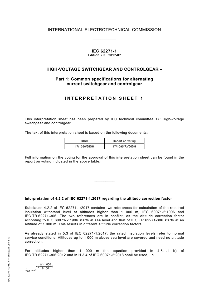
Interpretation of 4.2.2 of IEC 62271-1:2017 regarding the altitude correction factor
Subclause 4.2.2 of IEC 62271-1:2017 contains two references for calculation of the required
insulation withstand level at altitudes higher than 1 000 m, IEC 60071-2:1996 and
IEC TR 62271-306. The two references are in conflict, as the altitude correction factor
according to IEC 60071-2:1996 starts at sea level and that of IEC TR 62271-306 starts at an
altitude of 1 000 m. This results in different altitude correction factors.
As already stated in 5.3 of IEC 62271-1:2017, the rated insulation levels refer to normal
service conditions. Altitudes up to 1 000 m above sea level are covered and need no altitude
correction.
For altitudes higher than 1 000 m the equation provided in 4.5.1.1 b) of
IEC TR 62271-306:2012 and in H.3.4 of IEC 60071-2:2018 shall be used, i.e.
H−1 000
m( )
8 150
k = e
alt
IEC 62271-1:2017-07/ISH1:2021-05(en-fr)
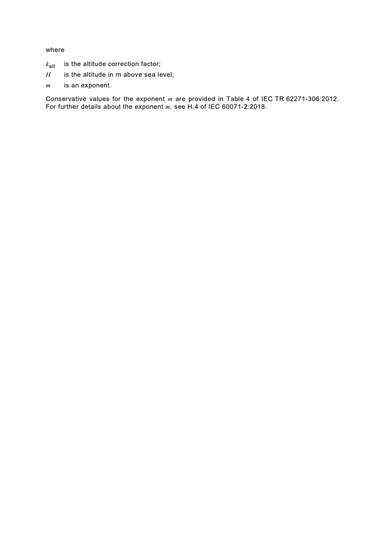
where
k is the altitude correction factor;
alt
H is the altitude in m above sea level;
m is an exponent.
Conservative values for the exponent m are provided in Table 4 of IEC TR 62271-306:2012.
For further details about the exponent m, see H.4 of IEC 60071-2:2018.
CONTENTS
FOREWORD . 11
INTRODUCTION to IEC 62271-1:2017+AMD1:2021 . 14
INTRODUCTION to IEC 62271-201:2026 . 15
1 Scope . 16
2 Normative references . 16
3 Terms and definitions . 19
3.1 General terms and definitions . 19
3.2 Assemblies of switchgear and controlgear . 24
3.3 Parts of assemblies . 24
3.4 Switching devices . 24
3.5 Parts of switchgear and controlgear . 25
3.6 Operational characteristics of switchgear and controlgear . 32
3.7 Characteristic quantities . 38
3.8 Index of definitions . 39
4 Normal and special service conditions . 42
4.1 Normal service conditions . 42
4.1.1 General . 42
4.1.2 Indoor switchgear and controlgear . 42
4.1.3 Outdoor switchgear and controlgear . 43
4.2 Special service conditions . 43
4.2.1 General . 43
4.2.2 Altitude . 44
4.2.3 Exposure to pollution . 44
4.2.4 Temperature and humidity . 44
4.2.5 Exposure to abnormal vibrations, shock or tilting . 44
4.2.6 Wind speed . 45
4.2.7 Other parameters . 45
5 Ratings . 45
5.1 General . 45
5.2 Rated voltage (U ) . 46
r
5.2.1 General . 46
5.2.2 Range I for rated voltages of 245 kV and below . 46
5.2.3 Range II for rated voltages above 245 kV . 46
5.3 Rated insulation level (U , U , U ) . 46
d p s
5.4 Rated frequency (f ) . 50
r
5.5 Rated continuous current (I ) . 50
r
5.6 Rated short-time withstand current (I ) . 50
k
5.6.101 Rated short-time withstand current (I ) . 51
k
5.6.102 Rated short-time phase to earth withstand current (I ) . 51
ke
5.7 Rated peak withstand current (I ) . 51
p
5.7.101 Rated peak withstand current (I ) . 52
p
5.7.102 Rated peak phase-to-earth withstand current (I ) . 52
pe
5.8 Rated duration of short-circuit (t ) . 52
k
5.8.101 Rated duration of short-circuit (t ) . 52
k
5.8.102 Rated duration of phase-to-earth short-circuit (t ) . 52
ke
5.9 Rated supply voltage of auxiliary and control circuits (U ) . 53
a
5.9.1 General . 53
5.9.2 Rated supply voltage (U ) . 53
a
5.10 Rated supply frequency of auxiliary and control circuits . 53
5.11 Rated pressure of compressed gas supply for controlled pressure systems . 54
5.101 Classification of earthing function through main switching device . 54
5.102 Rated cable test voltages (U , U ) . 54
ct (AC) ct (DC)
5.102.1 General . 54
5.102.2 Rated power-frequency cable test voltage U . 54
ct (AC)
5.102.3 Rated DC cable test voltage U with rated duration t . 54
ct (DC) ct (DC)
5.103 Ratings of the internal arc classification (IAC) . 54
5.103.1 General . 54
5.103.2 Types of accessibility . 55
5.103.3 Classified sides . 55
5.103.4 Rated arc fault currents (I , I ) . 55
A Ae
5.103.5 Rated arc fault duration (t , t ) . 55
A Ae
6 Design and construction . 56
6.1 Requirements for liquids in switchgear and controlgear . 56
6.2 Requirements for gases in switchgear and controlgear . 56
6.3 Earthing of switchgear and controlgear . 56
6.3.101 Earthing of the high-voltage conductive parts . 56
6.3.102 Earthing of enclosure(s) . 57
6.3.103 Earthing of withdrawable and removable parts . 57
6.3.104 Earthing circuit . 57
6.4 Auxiliary and control equipment and circuits . 58
6.4.1 General . 58
6.4.2 Protection against electric shock . 59
6.4.3 Components installed in enclosures . 59
6.5 Dependent power operation . 62
6.6 Stored energy operation. 62
6.6.1 General . 62
6.6.2 Energy storage in gas receivers or hydraulic accumulators . 62
6.6.3 Energy storage in springs (or weights) . 62
6.6.4 Manual charging . 62
6.6.5 Motor charging . 63
6.6.6 Energy storage in capacitors . 63
6.7 Independent unlatched operation (independent manual or power operation) . 63
6.8 Manually operated actuators . 63
6.9 Operation of releases. 64
6.9.1 General . 64
6.9.2 Shunt closing release . 64
6.9.3 Shunt opening release . 64
6.9.4 Capacitor operation of shunt releases . 64
6.9.5 Under-voltage release . 64
6.10 Pressure/level indication . 64
6.10.1 Gas pressure . 64
6.10.2 Liquid level . 65
6.11 Nameplates . 65
6.11.1 General . 65
6.11.2 Application. 65
6.12 Locking devices . 68
6.13 Position indication . 69
6.14 Degrees of protection provided by enclosures . 69
6.14.1 General . 69
6.14.2 Protection of persons against access to hazardous parts and protection
of the equipment against ingress of solid foreign objects (IP coding) . 69
6.14.3 Protection against ingress of water (IP coding) . 69
6.14.4 Protection against mechanical impact under normal service conditions
(IK coding) . 69
6.15 Creepage distances for outdoor insulators . 70
6.16 Gas and vacuum tightness . 70
6.16.1 General . 70
6.16.2 Controlled pressure systems for gas . 70
6.16.3 Closed pressure systems for gas . 70
6.16.4 Sealed pressure systems . 71
6.17 Tightness for liquid systems . 71
6.17.1 General . 71
6.17.2 Leakage rates . 71
6.18 Fire hazard (flammability) . 71
6.19 Electromagnetic compatibility (EMC) . 71
6.20 X-ray emission . 72
6.21 Corrosion . 72
6.22 Filling levels for insulation, switching and/or operation . 72
6.101 General requirements for assemblies . 72
6.102 Solid insulating enclosure . 73
6.102.1 General . 73
6.102.2 Covers and doors . 73
6.102.3 Partition or shutter being part of the enclosure . 74
6.102.4 Inspection windows . 75
6.102.5 Ventilating openings, vent outlets . 75
6.102.6 Protection category of the solid insulating enclosure against electric
shock . 75
6.102.7 Requirements for protection categories . 75
6.103 High-voltage compartments . 76
6.103.1 General . 76
6.103.2 Fluid-filled compartments (gas or liquid) . 77
6.103.3 Partitions and shutters . 78
6.104 Removable parts . 79
6.105 Provisions for dielectric tests on cables . 80
6.106 Internal arc fault . 80
7 Type tests . 80
7.1 General . 80
7.1.1 Basics . 80
7.1.2 Information for identification of test objects . 82
7.1.3 Information to be included in type-test reports . 82
7.2 Dielectric tests . 83
7.2.1 General . 83
7.2.2 Ambient air conditions during tests . 83
7.2.3 Wet test procedure . 83
7.2.4 Arrangement of the equipment . 83
7.2.5 Criteria to pass the test . 84
7.2.6 Application of the test voltage and test conditions . 85
7.2.7 Tests of switchgear and controlgear of U ≤ 245 kV . 89
r
7.2.8 Tests of switchgear and controlgear of U > 245 kV . 91
r
7.2.9 Artificial pollution tests for outdoor insulators . 91
7.2.10 Partial discharge tests . 91
7.2.11 Dielectric tests on auxiliary and control circuits . 91
7.2.12 Voltage test as condition check . 92
7.2.101 Dielectric tests on cable testing circuits . 92
7.3 Radio interference voltage (RIV) test . 92
7.4 Resistance measurement . 92
7.4.1 Measurement of the resistance of auxiliary contacts class 1 and class 2 . 92
7.4.2 Measurement of the resistance of auxiliary contacts class 3 . 93
7.4.3 Electrical continuity of earthed metallic parts test . 93
7.4.4 Resistance measurement of contacts and connections in the main
circuit as a condition check . 93
7.4.101 Requirement for protection category PB2. 94
7.5 Continuous current tests . 94
7.5.1 Condition of the test object . 94
7.5.2 Arrangement of the equipment . 94
7.5.3 Test current and duration . 95
7.5.4 Temperature measurement during test . 96
7.5.5 Resistance of the main circuit . 98
7.5.6 Criteria to pass test . 98
7.5.101 Test report . 102
7.6 Short-time withstand current and peak withstand current tests . 102
7.6.1 General . 102
7.6.2 Arrangement of the equipment and of the test circuit . 104
7.6.3 Test current and duration . 104
7.6.4 Conditions of the test object after test . 105
7.7 Verification of the protection . 106
7.7.1 Verification of the IP coding . 106
7.7.2 Verification of the IK coding . 106
7.8 Tightness tests . 107
7.8.1 General . 107
7.8.2 Controlled pressure systems for gas . 108
7.8.3 Closed pressure systems for gas . 108
7.8.4 Sealed pressure systems . 109
7.8.5 Liquid tightness tests . 109
7.9 Electromagnetic compatibility tests (EMC) . 110
7.9.1 Emission tests . 110
7.9.2 Immunity tests on auxiliary and control circuits . 112
7.9.3 Additional EMC tests on auxiliary and control circuits . 115
7.10 Additional tests on auxiliary and control circuits . 115
7.10.1 General . 115
7.10.2 Functional tests . 115
7.10.3 Verification of the operational characteristics of auxiliary contacts . 115
7.10.4 Environmental tests . 116
7.10.5 Dielectric test . 117
7.11 X-radiation test for vacuum interrupters . 118
7.11.1 General requirements . 118
7.11.2 Test voltage and measurement procedure . 119
7.11.3 Acceptance criteria . 119
7.101 Verification of making and breaking capacities . 120
7.101.1 General . 120
7.101.2 Test requirements for main switching devices . 120
7.101.3 Test requirements for earthing function . 121
7.102 Mechanical operation tests . 121
7.102.1 Switching devices and removable parts . 121
7.102.2 Mechanical and electromechanical interlocks and locking devices . 121
7.103 Pressure withstand test for gas-filled compartments . 123
7.103.1 Pressure withstand test for gas-filled compartments with pressure relief
devices . 123
7.103.2 Pressure withstand test for gas-filled compartments without pressure
relief devices . 124
7.104 Tests to verify the protection of persons against dangerous electrical effects . 124
7.104.1 General . 124
7.104.2 Dielectric tests . 125
7.104.3 Measurements of leakage currents . 125
7.105 Internal arc test . 126
7.105.1 General . 126
7.105.2 Test conditions . 126
7.105.3 Arrangement of the equipment . 127
7.105.4 Test procedure . 127
7.105.5 Criteria to pass the test . 128
7.105.6 Test report . 128
7.105.7 Extension of validity of test results . 129
7.106 Thermal stability test . 129
7.107 Humidity test . 130
8 Routine tests . 130
8.1 General . 130
8.2 Dielectric test on the main circuit . 131
8.3 Tests on auxiliary and control circuits . 131
8.3.1 Inspection of auxiliary and control circuits, and verification of conformity
to the circuit diagrams and wiring diagrams . 131
8.3.2 Functional tests . 132
8.3.3 Verification of protection against electrical shock . 132
8.3.4 Dielectric tests . 132
8.4 Measurement of the resistance of the main circuit . 132
8.5 Tightness test . 133
8.5.1 General . 133
8.5.2 Controlled pressure systems for gas . 133
8.5.3 Closed pressure systems for gas . 133
8.5.4 Sealed pressure systems . 133
8.5.5 Liquid tightness tests . 133
8.6 Design and visual checks . 134
8.101 Partial discharge measurement . 134
8.102 Mechanical operation tests . 134
8.103 Pressure tests of gas-filled compartments . 134
8.104 Tests after erection on site. 134
8.105 Measurement of fluid condition after filling on site . 135
9 Guide to the selection of switchgear and controlgear (informative) . 135
9.1 General . 135
9.2 Selection of rated values . 135
9.3 Cable-interface considerations . 136
9.4 Continuous or temporary overload due to changed service conditions . 136
9.5 Environmental aspects . 136
9.5.1 Service conditions . 136
9.5.2 Clearances affected by service conditions . 136
9.5.3 High humidity. 137
9.5.4 Solar radiation . 137
9.101 Selection of design and construction . 137
9.101.1 General . 137
9.101.2 Architecture and accessibility to high-voltage compartments . 137
9.101.3 Service continuity of the switchgear and controlgear . 138
9.102 Ratings related to earthing circuits . 141
9.103 Internal arc fault . 141
9.103.1 General . 141
9.103.2 Causes and preventive measures . 141
9.103.3 Supplementary protective measures . 142
9.103.4 Considerations for the selection and installation . 143
9.103.5 Internal arc test . 144
9.103.6 IAC classification . 144
9.104 Summary of technical requirements, ratings and optional tests . 145
10 Information to be given with enquiries, tenders and orders (informative) . 147
10.1 General . 147
10.2 Information with enquiries and orders . 148
10.3 Information with tenders . 149
11 Transport, storage, installation, operating instructions and maintenance . 149
11.1 General . 149
11.2 Conditions during transport, storage and installation . 150
11.3 Installation . 150
11.3.1 General . 150
11.3.2 Unpacking and lifting . 150
11.3.3 Assembly . 150
11.3.4 Mounting . 150
11.3.5 Connections . 150
11.3.6 Information about gas and gas mixtures for controlled and closed
pressure systems . 151
11.3.7 Final installation inspection . 151
11.3.8 Basic input data by the user . 152
11.3.9 Basic input data by the manufacturer . 152
11.4 Operating instructions . 152
11.5 Maintenance . 153
11.5.1 General . 153
11.5.2 Information about fluids and gas to be included in maintenance manual . 153
11.5.3 Recommendations for the manufacturer. 153
11.5.4 Recommendations for the user . 155
11.5.5 Failure report . 155
12 Safety . 156
12.1 General . 156
12.2 Precautions by manufacturers . 157
12.3 Precautions by users . 157
12.101 Procedures . 158
12.102 Internal arc aspects . 158
13 Influence of the product on the environment . 158
Annex A (normative) Identification of test objects . 159
A.1 General . 159
A.2 Data . 159
A.3 Drawings . 159
Annex B (informative) Determination of the equivalent RMS value of a short-time
current during a short-circuit of a given duration . 161
Annex C (normative) Method for the weatherproofing test for outdoor switchgear and
controlgear . 162
Annex D (informative) References for auxiliary and control circuit components . 165
Annex E (normative) Tolerances on test quantities during tests . 167
Annex F (informative) Information and technical requirements to be given with
enquiries, tenders and orders . 170
F.1 General . 170
F.2 Normal and special service conditions (refer to Clause 4) . 170
F.3 Ratings (refer to Clause 5) . 171
F.4 Design and construction (refer to Clause 6) . 171
F.5 System information . 172
F.6 Documentation for enquiries and tenders . 172
Annex G (informative) List of symbols . 173
Annex H (informative) Electromagnetic compatibility on site . 174
Annex I (informative) List of notes concerning certain countries . 175
Annex J (informative) Extension of validity of type tests . 176
J.1 General . 176
J.2 Dielectric tests . 176
J.3 Short-time withstand current tests . 176
J.4 Continuous current test . 176
J.5 Electromagnetic immunity test on auxiliary and control circuits . 177
J.6 Environmental tests on auxiliary and control circuits . 177
Annex K (informative) Exposure to pollution . 178
K.1 General . 178
K.2 Pollution levels . 178
K.3 Minimum requirements for switchgear . 178
Annex A (normative) Internal arc fault – Method to verify the internal arc classification
(IAC) . 180
A.1 Room simulation . 180
A.2 Indicators (for assessing the thermal effects of the gases) . 182
A.2.1 General . 182
A.2.2 Arrangement of indicators . 182
A.3 Tolerances for geometrical dimensions of test arrangements . 183
A.4 Test parameters .
...
IEC 62271-201 ®
Edition 3.0 2026-07
INTERNATIONAL
STANDARD
High-voltage switchgear and controlgear -
Part 201: AC solid-insulation enclosed switchgear and controlgear for rated
voltages above 1 kV and up to and including 52 kV
ICS 29.130.10 ISBN 978-2-8327-1300-6
All rights reserved. Unless otherwise specified, no part of this publication may be reproduced or utilized in any form or
by any means, electronic or mechanical, including photocopying and microfilm, without permission in writing from either
IEC or IEC's member National Committee in the country of the requester. If you have any questions about IEC copyright
or have an enquiry about obtaining additional rights to this publication, please contact the address below or your local
IEC member National Committee for further information.
IEC Secretariat Tel.: +41 22 919 02 11
3, rue de Varembé info@iec.ch
CH-1211 Geneva 20 www.iec.ch
Switzerland
About the IEC
The International Electrotechnical Commission (IEC) is the leading global organization that prepares and publishes
International Standards for all electrical, electronic and related technologies.
About IEC publications
The technical content of IEC publications is kept under constant review by the IEC. Please make sure that you have the
latest edition, a corrigendum or an amendment might have been published.
IEC publications search - IEC Products & Services Portal - products.iec.ch
webstore.iec.ch/advsearchform Discover our powerful search engine and read freely all the
The advanced search enables to find IEC publications by a publications previews, graphical symbols and the glossary.
variety of criteria (reference number, text, technical With a subscription you will always have access to up to date
committee, …). It also gives information on projects, content tailored to your needs.
replaced and withdrawn publications.
Electropedia - www.electropedia.org
The world's leading online dictionary on electrotechnology,
IEC Just Published - webstore.iec.ch/justpublished
Stay up to date on all new IEC publications. Just Published containing more than 22 500 terminological entries in English
details all new publications released. Available online and and French, with equivalent terms in 25 additional languages.
once a month by email. Also known as the International Electrotechnical Vocabulary
(IEV) online.
IEC Customer Service Centre - webstore.iec.ch/csc
If you wish to give us your feedback on this publication or
need further assistance, please contact the Customer
Service Centre: sales@iec.ch.
CONTENTS
FOREWORD . 8
INTRODUCTION . 11
1 Scope . 12
2 Normative references . 12
3 Terms and definitions . 13
3.1 General terms and definitions . 13
3.2 Assemblies of switchgear and controlgear . 15
3.3 Parts of assemblies . 15
3.4 Switching devices . 15
3.5 Parts of switchgear and controlgear . 15
3.6 Operational characteristics of switchgear and controlgear . 19
3.7 Characteristic quantities . 21
3.8 Index of definitions . 22
4 Normal and special service conditions . 23
5 Ratings . 24
5.1 General . 24
5.2 Rated voltage (U ) . 24
r
5.3 Rated insulation level (U , U , U ) . 24
d p s
5.4 Rated frequency (f ) . 24
r
5.5 Rated continuous current (I ) . 24
r
5.6 Rated short-time withstand current (I , I ) . 25
k ke
5.6.101 Rated short-time withstand current (I ) . 25
k
5.6.102 Rated short-time phase to earth withstand current (I ) . 25
ke
5.7 Rated peak withstand current (I , I ) . 25
p pe
5.7.101 Rated peak withstand current (I ) . 25
p
5.7.102 Rated peak phase-to-earth withstand current (I ) . 25
pe
5.8 Rated durations of short-circuit (t , t ) . 26
k ke
5.8.101 Rated duration of short-circuit (t ) . 26
k
5.8.102 Rated duration of phase-to-earth short-circuit (t ) . 26
ke
5.9 Rated supply voltage of auxiliary and control circuits (U ) . 26
a
5.10 Rated supply frequency of auxiliary circuits . 26
5.11 Rated pressure of compressed gas supply for controlled pressure systems . 26
5.101 Classification of earthing function through main switching device . 26
5.102 Rated cable test voltages (U , U ) . 26
ct (AC) ct (DC)
5.102.1 General . 26
5.102.2 Rated power-frequency cable test voltage U . 27
ct (AC)
5.102.3 Rated DC cable test voltage U with rated duration t . 27
ct (DC) ct (DC)
5.103 Ratings of the internal arc classification (IAC) . 27
5.103.1 General . 27
5.103.2 Types of accessibility . 27
5.103.3 Classified sides . 27
5.103.4 Rated arc fault currents (I , I ) . 28
A Ae
5.103.5 Rated arc fault duration (t , t ) . 28
A Ae
6 Design and construction . 28
6.1 Requirements for liquids in switchgear and controlgear . 28
6.2 Requirements for gases in switchgear and controlgear . 28
6.3 Earthing of switchgear and controlgear . 28
6.3.101 Earthing of the high-voltage conductive parts . 28
6.3.102 Earthing of enclosure(s) . 29
6.3.103 Earthing of withdrawable and removable parts . 29
6.3.104 Earthing circuit . 29
6.4 Auxiliary and control equipment . 30
6.5 Dependent power operation . 30
6.6 Stored energy operation. 30
6.7 Independent unlatched operation (independent manual or power operation) . 30
6.8 Manually operated actuators . 30
6.9 Operation of releases. 30
6.10 Pressure/level indication . 30
6.11 Nameplates . 31
6.12 Locking devices . 33
6.13 Position indication . 34
6.14 Degrees of protection provided by enclosures . 34
6.14.1 General . 34
6.14.2 Protection of persons against access to hazardous parts and protection
of the equipment against ingress of solid foreign objects (IP coding) . 34
6.14.3 Protection against ingress of water (IP coding) . 34
6.14.4 Protection of equipment against mechanical impact under normal
service conditions (IK coding) . 34
6.15 Creepage distances for outdoor insulators . 34
6.16 Gas and vacuum tightness . 34
6.17 Tightness for liquid systems . 34
6.18 Fire hazard (flammability) . 34
6.19 Electromagnetic compatibility (EMC) . 34
6.20 X-ray emission . 34
6.21 Corrosion . 35
6.22 Filling levels for insulation, switching and/or operation . 35
6.101 General requirements for assemblies . 35
6.102 Solid insulating enclosure . 36
6.102.1 General . 36
6.102.2 Covers and doors . 36
6.102.3 Partition or shutter being part of the enclosure . 37
6.102.4 Inspection windows . 37
6.102.5 Ventilating openings, vent outlets . 37
6.102.6 Protection category of the solid insulating enclosure against electric
shock . 38
6.102.7 Requirements for protection categories . 38
6.103 High-voltage compartments . 39
6.103.1 General . 39
6.103.2 Fluid-filled compartments (gas or liquid) . 40
6.103.3 Partitions and shutters . 41
6.104 Removable parts . 42
6.105 Provisions for dielectric tests on cables . 43
6.106 Internal arc fault . 43
7 Type tests . 43
7.1 General . 43
7.1.1 Basics . 43
7.1.2 Information for identification of specimens . 44
7.1.3 Information to be included in type-test reports . 44
7.2 Dielectric tests . 44
7.2.1 General . 44
7.2.2 Ambient air conditions during tests . 45
7.2.3 Wet test procedure . 45
7.2.4 Conditions of switchgear and controlgear during dielectric tests . 45
7.2.5 Criteria to pass the test . 45
7.2.6 Application of the test voltage and test conditions . 45
7.2.7 Tests of switchgear and controlgear of U ≤ 245 kV . 46
r
7.2.8 Tests of switchgear and controlgear of U >245 kV . 47
r
7.2.9 Artificial pollution tests for outdoor insulators . 48
7.2.10 Partial discharge tests . 48
7.2.11 Dielectric tests on auxiliary and control circuits . 48
7.2.12 Voltage test as condition check . 48
7.2.101 Dielectric tests on cable testing circuits . 49
7.3 Radio interference voltage (RIV) test . 49
7.4 Resistance measurement . 49
7.4.1 Measurement of the resistance of auxiliary contacts class 1 and class 2 . 49
7.4.2 Measurement of the resistance of auxiliary contacts class 3 . 49
7.4.3 Electrical continuity of earthed metallic parts test . 49
7.4.4 Resistance measurement of contacts and connections in the main
circuit as a condition check . 49
7.4.101 Requirement for protection category PB2. 49
7.5 Continuous current tests . 50
7.5.1 Condition of the test object . 50
7.5.2 Arrangement of the equipment . 50
7.5.3 Test current and duration . 50
7.5.4 Temperature measurement during test . 50
7.5.5 Resistance of the main circuit . 51
7.5.6 Criteria to pass the test . 51
7.5.101 Test report . 51
7.6 Short-time withstand current and peak withstand current tests . 51
7.6.1 General . 51
7.6.2 Arrangement of the equipment and of the test circuit . 52
7.6.3 Test current and duration . 53
7.6.4 Condition of test object after test . 53
7.7 Verification of the protection . 54
7.7.1 Verification of the IP coding . 54
7.7.2 Verification of the IK coding . 54
7.8 Tightness tests . 54
7.9 Electromagnetic compatibility tests (EMC) . 54
7.10 Additional tests on auxiliary and control circuits . 54
7.10.1 General . 54
7.10.2 Functional tests . 55
7.10.3 Verification of the operational characteristics of auxiliary contacts . 55
7.10.4 Environmental tests . 55
7.10.5 Dielectric test . 55
7.11 X-radiation test procedures for vacuum interrupters . 55
7.101 Verification of making and breaking capacities . 55
7.101.1 General . 55
7.101.2 Test requirements for main switching devices . 56
7.101.3 Test requirements for earthing function . 56
7.102 Mechanical operation tests . 56
7.102.1 Switching devices and removable parts . 56
7.102.2 Mechanical and electromechanical interlocks and locking devices . 57
7.103 Pressure withstand test for gas-filled compartments . 59
7.103.1 Pressure withstand test for gas-filled compartments with pressure relief
devices . 59
7.103.2 Pressure withstand test for gas-filled compartments without pressure
relief devices . 60
7.104 Tests to verify the protection of persons against dangerous electrical effects . 60
7.104.1 General . 60
7.104.2 Dielectric tests . 60
7.104.3 Measurements of leakage currents . 61
7.105 Internal arc test . 61
7.105.1 General . 61
7.105.2 Test conditions . 62
7.105.3 Arrangement of the equipment . 63
7.105.4 Test procedure . 63
7.105.5 Criteria to pass the test . 63
7.105.6 Test report . 64
7.105.7 Extension of validity of test results . 65
7.106 Thermal stability test . 65
7.107 Humidity test . 66
8 Routine tests . 66
8.1 General . 66
8.2 Dielectric test on the main circuit . 66
8.3 Tests on auxiliary and control circuits . 66
8.3.1 Inspection of auxiliary and control circuits, and verification of conformity
to the circuit diagrams and wiring diagrams . 66
8.3.2 Functional tests . 67
8.3.3 Verification of protection against electrical shock . 67
8.3.4 Dielectric tests . 67
8.4 Measurement of the resistance of the main circuit . 67
8.5 Tightness test . 67
8.6 Design and visual checks . 67
8.101 Partial discharge measurement . 67
8.102 Mechanical operation tests . 68
8.103 Pressure tests of gas-filled compartments . 68
8.104 Tests after erection on site. 68
8.105 Measurement of fluid condition after filling on site . 69
9 Guide to the selection of switchgear and controlgear (informative) . 69
9.1 General . 69
9.2 Selection of rated values . 69
9.3 Cable-interface considerations . 70
9.4 Continuous or temporary overload due to changed service conditions . 70
9.5 Environmental aspects . 70
9.101 Selection of design and construction . 70
9.101.1 General . 70
9.101.2 Architecture and accessibility to high-voltage compartments . 71
9.101.3 Service continuity of the switchgear and controlgear . 72
9.102 Ratings related to earthing circuits . 74
9.103 Internal arc fault . 74
9.103.1 General . 74
9.103.2 Causes and preventive measures . 75
9.103.3 Supplementary protective measures . 75
9.103.4 Considerations for the selection and installation . 76
9.103.5 Internal arc test . 77
9.103.6 IAC classification . 78
9.104 Summary of technical requirements, ratings and optional tests . 79
10 Information to be given with enquiries, tenders and orders (informative) . 81
10.1 General . 81
10.2 Information with enquiries and orders . 81
10.3 Information with tenders . 82
11 Transport, storage, installation, operating instructions and maintenance . 83
11.1 General . 83
11.2 Conditions during transport, storage and installation . 83
11.3 Installation . 83
11.4 Operating instructions . 83
11.5 Maintenance . 84
12 Safety . 84
12.101 Procedures . 84
12.102 Internal arc aspects . 84
13 Influence of the product on the environment . 84
Annex A (normative) Internal arc fault – Method to verify the internal arc classification
(IAC) . 85
A.1 Room simulation . 85
A.2 Indicators (for assessing the thermal effects of the gases) . 87
A.2.1 General . 87
A.2.2 Arrangement of indicators . 87
A.3 Tolerances for geometrical dimensions of test arrangements . 88
A.4 Test parameters . 88
A.4.1 General . 88
A.4.2 Voltage . 88
A.4.3 Current . 88
A.4.4 Frequency . 89
A.5 Test procedure. 89
A.5.1 Supply circuit . 89
A.5.2 Arc initiation . 90
Annex B (normative) Partial discharge measurement . 99
B.1 General . 99
B.2 Application . 99
B.3 Test circuits and measuring instruments . 100
B.4 Test procedure. 100
Annex C (informative) Regional deviations . 105
Annex D (normative) Humidity test . 106
D.1 General . 106
D.2 Test procedure and test conditions . 106
D.2.1 Test cycle and its duration . 106
D.2.2 Generation of fog . 107
D.2.3 High air temperature period . 107
D.2.4 Test chamber . 107
D.2.5 Test object. 107
D.2.6 Test voltage and voltage supply. 108
D.2.7 Total test duration. 108
D.3 Test criteria and evaluation . 108
D.3.1 Criterion during the test . 108
D.3.2 Criterion after the test . 108
D.3.3 Evaluation of the test . 108
Annex E (informative) Protection categories . 110
E.1 Protection category PA . 110
E.2 Protection categories PB. 111
Annex F (informative) List of symbols and abbreviations used in IEC 62271-201 . 112
Annex G (normative) Flowchart categorisation procedure LSC for a given functional
unit FU1 with connection compartment . 113
Annex H (informative) Pressure coordination chart for gas-filled compartments . 114
Bibliography . 115
Figure 1 – LSC1. 73
Figure 2 – LSC2. 73
Figure 3 – LSC2. 73
Figure 4 – LSC2. 74
Figure 5 – LSC2A . 74
Figure 6 – LSC2B . 74
Figure 7 – LSC2B . 74
Figure 8 – No LSC assigned . 74
Figure 9 – No LSC assigned . 74
Figure A.1 – Mounting frame for vertical indicators . 92
Figure A.2 – Horizontal indicator . 92
Figure A.3 – Position of the indicators. 93
Figure A.4 – Room simulation and indicator positioning for accessibility A, classified
rear side, ceiling above 2 000 mm, functional unit of any height . 94
Figure A.5 – Ceiling height stated from the floor or false floor level where the
switchgear is actually placed . 96
Figure A.6 – Indicator positioning in case of protrusion at < 2 000 mm height, at
classified side . 97
Figure A.7 – Indicator positioning in case a bottom exhaust duct belonging to the
assembly is defined as a walkable integrated part of the false floor . 97
Figure A.8 – Room simulation and indicator positioning for accessibility type A, non-
accessible rear side, ceiling at 2 000 mm, so functional unit ≤ 1 800 mm high . 98
Figure B.1 – Partial discharge test circuit (three-phase arrangement) . 103
Figure B.2 – Partial discharge test circuit (system without earthed neutral) . 104
Figure D.1 – Test cycle . 109
Figure D.2 – Test chamber . 109
Figure E.1 – Possible designs for protection category PA . 110
Figure E.2 – Possible designs for protection category PB . 111
Figure G.1 – Flowchart categorisation procedure LSC for a given functional unit FU1
with connection compartment . 113
Figure H.1 – Example of pressure coordination chart . 114
Table 1 – Nameplate information . 31
Table 2 – Locations, causes and examples of measures to decrease the probability of
internal arc faults . 76
Table 3 – Single-phase-to-earth arc fault current depending on the network neutral
earthing . 78
Table 4 – Summary of technical requirements, ratings and optional tests for
assemblies . 79
Table A.1 – Parameters for internal arc test according to compartment construction . 91
Table B.1 – Test circuits and procedures . 102
INTERNATIONAL ELECTROTECHNICAL COMMISSION
____________
High-voltage switchgear and controlgear -
Part 201: AC solid-insulation enclosed switchgear
and controlgear for rated voltages above 1 kV
and up to and including 52 kV
FOREWORD
1) The International Electrotechnical Commission (IEC) is a worldwide organization for standardization comprising
all national electrotechnical committees (IEC National Committees). The object of IEC is to promote international
co-operation on all questions concerning standardization in the electrical and electronic fields. To this end and
in addition to other activities, IEC publishes International Standards, Technical Specifications, Technical Reports,
Publicly Available Specifications (PAS) and Guides (hereafter referred to as “IEC Publication(s)”). Their
preparation is entrusted to technical committees; any IEC National Committee interested in the subject dealt with
may participate in this preparatory work. International, governmental and non-governmental organizations liaising
with the IEC also participate in this preparation. IEC collaborates closely with the International Organization for
Standardization (ISO) in accordance with conditions determined by agreement between the two organizations.
2) The formal decisions or agreements of IEC on technical matters express, as nearly as possible, an international
consensus of opinion on the relevant subjects since each technical committee has representation from all
interested IEC National Committees.
3) IEC Publications have the form of recommendations for international use and are accepted by IEC National
Committees in that sense. While all reasonable efforts are made to ensure that the technical content of IEC
Publications is accurate, IEC cannot be held responsible for the way in which they are used or for any
misinterpretation by any end user.
4) In order to promote international uniformity, IEC National Committees undertake to apply IEC Publications
transparently to the maximum extent possible in their national and regional publications. Any divergence between
any IEC Publication and the corresponding national or regional publication shall be clearly indicated in the latter.
5) IEC itself does not provide any attestation of conformity. Independent certification bodies provide conformity
assessment services and, in some areas, access to IEC marks of conformity. IEC is not responsible for any
services carried out by independent certification bodies.
6) All users should ensure that they have the latest edition of this publication.
7) No liability shall attach to IEC or its directors, employees, servants or agents including individual experts and
members of its technical committees and IEC National Committees for any personal injury, property damage or
other damage of any nature whatsoever, whether direct or indirect, or for costs (including legal fees) and
expenses arising out of the publication, use of, or reliance upon, this IEC Publication or any other IEC
Publications.
8) Attention is drawn to the Normative references cited in this publication. Use of the referenced publications is
indispensable for the correct application of this publication.
9) IEC draws attention to the possibility that the implementation of this document may involve the use of (a)
patent(s). IEC takes no position concerning the evidence, validity or applicability of any claimed patent rights in
respect thereof. As of the date of publication of this document, IEC had not received notice of (a) patent(s), which
may be required to implement this document. However, implementers are cautioned that this may not represent
the latest information, which may be obtained from the patent database available at https://patents.iec.ch. IEC
shall not be held responsible for identifying any or all such patent rights.
IEC 62271-201 has been prepared by subcommittee 17C: Assemblies, of IEC technical
committee 17: High-voltage switchgear and controlgear. It is an International Standard.
This third edition cancels and replaces the second edition published in 2014. This edition
constitutes a technical revision.
This edition includes the following significant technical changes with respect to the previous
edition:
a) aligned with the third edition of IEC 62271-200 published in 2021 and its Amendment 1
published in 2024, for structure, definitions, classifications, ratings and testing procedures,
where appropriate;
b) clause numbering aligned with IEC 62271-1:2017, including the adoption of the subclause
names of Clause 3;
c) in Clause 3 specific terms and definitions are added for "in service", "normal operating
condition" and "normal use";
d) earthing circuit is more precisely described, including ratings and test requirements;
e) number of mechanical tests on interlocks is reduced for type testing;
f) forces to apply during type testing are better prescribed (refer to 7.102);
g) resistance measuring on main circuit is only needed before continuous current tests (as
reference for routine tests) and not anymore needed after this continuous current test.
Rationale for this deletion is that this measured resistance does not mean anything; as the
temperature rise test was just finished, a new temperature rise test will not give new
information;
h) IEC 62271-100:2021 has been taken into account in 7.101.2;
i) IEC 62271-107:2019 and IEC IEEE 62271-37-013:2021 are also considered in 7.101.2;
j) LSC category is more precisely described, including an explaining flowchart (Annex G);
k) examples not covered by the IAC test are transferred from Clause 6 to 9.103;
l) the term "assembly" is defined in Clause 3 and used as synonym for "solid-insulation
enclosed switchgear and controlgear" in this document;
m) "metallic" is replaced by "metal" where applicable;
n) a 1 s rule was introduced for Criterion 4 during IAC tests regarding hot gases versus glowing
particles as cause of ignition;
o) internal arc te
...
IEC 62271-201 ®
Edition 3.0 2026-07
NORME
INTERNATIONALE
Appareillage à haute tension -
Partie 201: Appareillage sous enveloppe isolante solide pour courant alternatif
de tensions assignées supérieures à 1 kV et inférieures ou égales à 52 kV
ICS 29.130.10 ISBN 978-2-8327-1300-6
Droits de reproduction réservés. Sauf indication contraire, aucune partie de cette publication ne peut être reproduite ni
utilisée sous quelque forme que ce soit et par aucun procédé, électronique ou mécanique, y compris la photocopie et
les microfilms, sans l'accord écrit de l'IEC ou du Comité national de l'IEC du pays du demandeur. Si vous avez des
questions sur le copyright de l'IEC ou si vous désirez obtenir des droits supplémentaires sur cette publication, utilisez
les coordonnées ci-après ou contactez le Comité national de l'IEC de votre pays de résidence.
IEC Secretariat Tel.: +41 22 919 02 11
3, rue de Varembé info@iec.ch
CH-1211 Geneva 20 www.iec.ch
Switzerland
A propos de l'IEC
La Commission Electrotechnique Internationale (IEC) est la première organisation mondiale qui élabore et publie des
Normes internationales pour tout ce qui a trait à l'électricité, à l'électronique et aux technologies apparentées.
A propos des publications IEC
Le contenu technique des publications IEC est constamment revu. Veuillez vous assurer que vous possédez l’édition la
plus récente, un corrigendum ou amendement peut avoir été publié.
Recherche de publications IEC - IEC Products & Services Portal - products.iec.ch
webstore.iec.ch/advsearchform Découvrez notre puissant moteur de recherche et consultez
La recherche avancée permet de trouver des publications gratuitement tous les aperçus des publications, symboles
IEC en utilisant différents critères (numéro de référence, graphiques et le glossaire. Avec un abonnement, vous aurez
texte, comité d’études, …). Elle donne aussi des toujours accès à un contenu à jour adapté à vos besoins.
informations sur les projets et les publications remplacées
ou retirées. Electropedia - www.electropedia.org
Le premier dictionnaire d'électrotechnologie en ligne au
IEC Just Published - webstore.iec.ch/justpublished monde, avec plus de 22 500 articles terminologiques en
Restez informé sur les nouvelles publications IEC. Just anglais et en français, ainsi que les termes équivalents
dans 25 langues additionnelles. Egalement appelé
Published détaille les nouvelles publications parues.
Disponible en ligne et une fois par mois par email. Vocabulaire Electrotechnique International (IEV) en ligne.
Service Clients - webstore.iec.ch/csc
Si vous désirez nous donner des commentaires sur cette
publication ou si vous avez des questions contactez-
nous: sales@iec.ch.
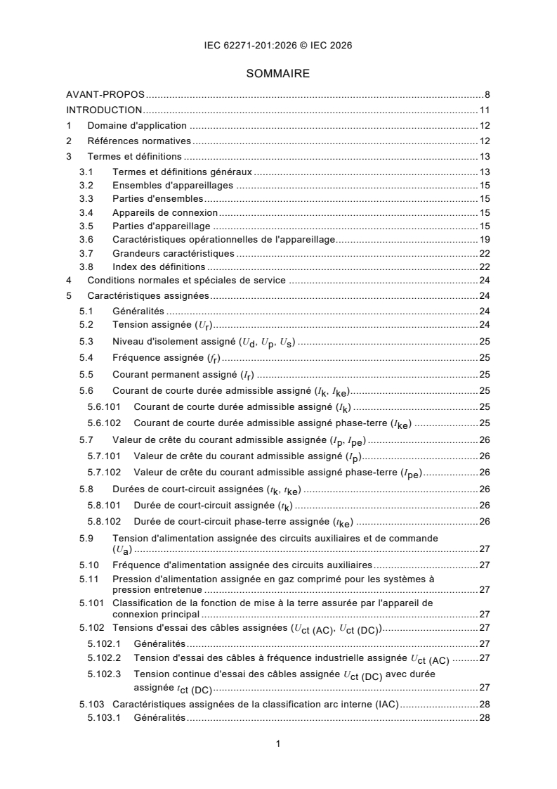
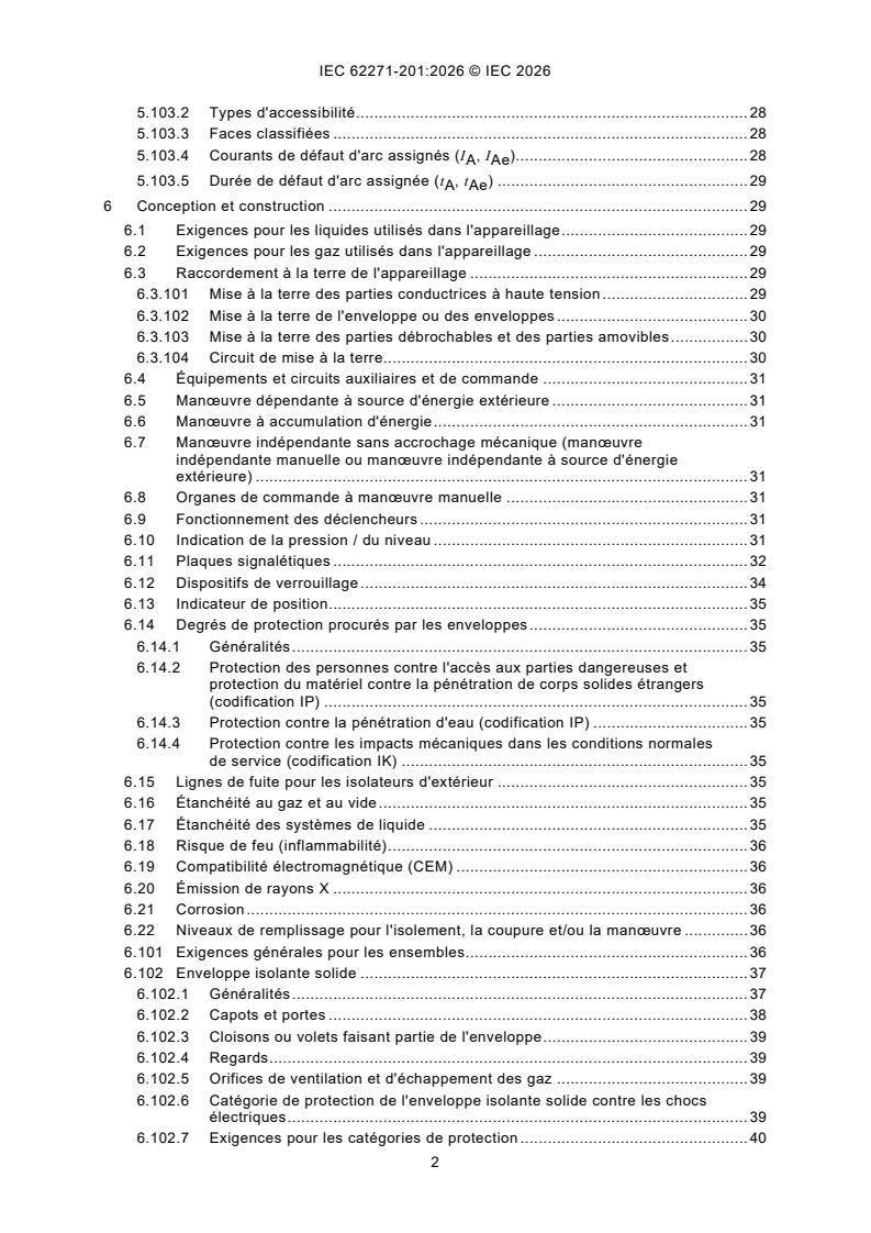
SOMMAIRE
AVANT-PROPOS . 8
INTRODUCTION . 11
1 Domaine d'application . 12
2 Références normatives . 12
3 Termes et définitions . 13
3.1 Termes et définitions généraux . 13
3.2 Ensembles d'appareillages . 15
3.3 Parties d'ensembles . 15
3.4 Appareils de connexion . 15
3.5 Parties d'appareillage . 15
3.6 Caractéristiques opérationnelles de l'appareillage. 19
3.7 Grandeurs caractéristiques . 22
3.8 Index des définitions . 22
4 Conditions normales et spéciales de service . 24
5 Caractéristiques assignées . 24
5.1 Généralités . 24
5.2 Tension assignée (U ) . 24
r
5.3 Niveau d'isolement assigné (U , U , U ) . 25
d p s
5.4 Fréquence assignée (f ) . 25
r
5.5 Courant permanent assigné (I ) . 25
r
5.6 Courant de courte durée admissible assigné (I , I ). 25
k ke
5.6.101 Courant de courte durée admissible assigné (I ) . 25
k
5.6.102 Courant de courte durée admissible assigné phase-terre (I ) . 25
ke
5.7 Valeur de crête du courant admissible assignée (I , I ) . 26
p pe
5.7.101 Valeur de crête du courant admissible assigné (I ) . 26
p
5.7.102 Valeur de crête du courant admissible assigné phase-terre (I ) . 26
pe
5.8 Durées de court-circuit assignées (t , t ) . 26
k ke
5.8.101 Durée de court-circuit assignée (t ) . 26
k
5.8.102 Durée de court-circuit phase-terre assignée (t ) . 26
ke
5.9 Tension d'alimentation assignée des circuits auxiliaires et de commande
(U ) . 27
a
5.10 Fréquence d'alimentation assignée des circuits auxiliaires . 27
5.11 Pression d'alimentation assignée en gaz comprimé pour les systèmes à
pression entretenue . 27
5.101 Classification de la fonction de mise à la terre assurée par l'appareil de
connexion principal . 27
5.102 Tensions d'essai des câbles assignées (U , U ) . 27
ct (AC) ct (DC)
5.102.1 Généralités . 27
5.102.2 Tension d'essai des câbles à fréquence industrielle assignée U . 27
ct (AC)
5.102.3 Tension continue d'essai des câbles assignée U avec durée
ct (DC)
assignée t . 27
ct (DC)
5.103 Caractéristiques assignées de la classification arc interne (IAC) . 28
5.103.1 Généralités . 28
5.103.2 Types d'accessibilité . 28
5.103.3 Faces classifiées . 28
5.103.4 Courants de défaut d'arc assignés (I , I ). 28
A Ae
5.103.5 Durée de défaut d'arc assignée (t , t ) . 29
A Ae
6 Conception et construction . 29
6.1 Exigences pour les liquides utilisés dans l'appareillage . 29
6.2 Exigences pour les gaz utilisés dans l'appareillage . 29
6.3 Raccordement à la terre de l'appareillage . 29
6.3.101 Mise à la terre des parties conductrices à haute tension . 29
6.3.102 Mise à la terre de l'enveloppe ou des enveloppes . 30
6.3.103 Mise à la terre des parties débrochables et des parties amovibles . 30
6.3.104 Circuit de mise à la terre. 30
6.4 Équipements et circuits auxiliaires et de commande . 31
6.5 Manœuvre dépendante à source d'énergie extérieure . 31
6.6 Manœuvre à accumulation d'énergie . 31
6.7 Manœuvre indépendante sans accrochage mécanique (manœuvre
indépendante manuelle ou manœuvre indépendante à source d'énergie
extérieure) . 31
6.8 Organes de commande à manœuvre manuelle . 31
6.9 Fonctionnement des déclencheurs . 31
6.10 Indication de la pression / du niveau . 31
6.11 Plaques signalétiques . 32
6.12 Dispositifs de verrouillage . 34
6.13 Indicateur de position . 35
6.14 Degrés de protection procurés par les enveloppes . 35
6.14.1 Généralités . 35
6.14.2 Protection des personnes contre l'accès aux parties dangereuses et
protection du matériel contre la pénétration de corps solides étrangers
(codification IP) . 35
6.14.3 Protection contre la pénétration d'eau (codification IP) . 35
6.14.4 Protection contre les impacts mécaniques dans les conditions normales
de service (codification IK) . 35
6.15 Lignes de fuite pour les isolateurs d'extérieur . 35
6.16 Étanchéité au gaz et au vide . 35
6.17 Étanchéité des systèmes de liquide . 35
6.18 Risque de feu (inflammabilité) . 36
6.19 Compatibilité électromagnétique (CEM) . 36
6.20 Émission de rayons X . 36
6.21 Corrosion . 36
6.22 Niveaux de remplissage pour l'isolement, la coupure et/ou la manœuvre . 36
6.101 Exigences générales pour les ensembles. 36
6.102 Enveloppe isolante solide . 37
6.102.1 Généralités . 37
6.102.2 Capots et portes . 38
6.102.3 Cloisons ou volets faisant partie de l'enveloppe . 39
6.102.4 Regards . 39
6.102.5 Orifices de ventilation et d'échappement des gaz . 39
6.102.6 Catégorie de protection de l'enveloppe isolante solide contre les chocs
électriques . 39
6.102.7 Exigences pour les catégories de protection . 40
6.103 Compartiments à haute tension . 40
6.103.1 Généralités . 40
6.103.2 Compartiments à remplissage de fluide (gaz ou liquide) . 42
6.103.3 Cloisons et volets . 43
6.104 Parties amovibles . 44
6.105 Dispositions pour les essais diélectriques des câbles . 45
6.106 Défaut d'arc interne . 45
7 Essais de type . 45
7.1 Généralités . 45
7.1.1 Principes fondamentaux . 45
7.1.2 Informations pour l'identification des échantillons d'essai . 46
7.1.3 Informations à inclure dans les rapports d'essais de type . 46
7.2 Essais diélectriques . 47
7.2.1 Généralités . 47
7.2.2 Conditions de l'air ambiant pendant les essais . 47
7.2.3 Modalités des essais sous pluie . 47
7.2.4 État de l'appareillage pendant les essais diélectriques . 47
7.2.5 Conditions de réussite des essais . 47
7.2.6 Application de la tension d'essai et conditions d'essai . 47
7.2.7 Essais de l'appareillage de U ≤ 245 kV . 49
r
7.2.8 Essais de l'appareillage de U > 245 kV . 50
r
7.2.9 Essais de pollution artificielle pour les isolateurs d'extérieur . 50
7.2.10 Essais de décharges partielles . 50
7.2.11 Essais diélectriques sur les circuits auxiliaires et de commande . 51
7.2.12 Essai de tension comme essai de vérification d'état . 51
7.2.101 Essais diélectriques sur les circuits d'essai des câbles . 51
7.3 Essai de tension de perturbation radioélectrique . 51
7.4 Mesurage de la résistance . 51
7.4.1 Mesurage de la résistance des circuits auxiliaires de classes 1 et 2 . 51
7.4.2 Mesurage de la résistance des contacts auxiliaires de classe 3 . 51
7.4.3 Essai de continuité électrique des parties métalliques reliées à la terre . 52
7.4.4 Mesurage de la résistance des contacts et des connexions dans le
circuit principal sous forme de vérification d'état . 52
7.4.101 Exigences pour la catégorie de protection PB2 . 52
7.5 Essais au courant permanent . 52
7.5.1 État de l'objet d'essai . 52
7.5.2 Disposition de l'appareil . 52
7.5.3 Valeurs du courant d'essai et de sa durée . 53
7.5.4 Mesurage de la température pendant l'essai . 53
7.5.5 Résistance du circuit principal . 53
7.5.6 Conditions de réussite des essais . 53
7.5.101 Rapport d'essai. 54
7.6 Essais au courant de courte durée admissible et à la valeur de crête du
courant admissible . 54
7.6.1 Généralités . 54
7.6.2 Disposition de l'appareil et du circuit d'essai . 55
7.6.3 Valeurs du courant d'essai et de sa durée . 56
7.6.4 État de l'objet d'essai après l'essai . 56
7.7 Vérification de la protection . 57
7.7.1 Vérification de la codification IP . 57
7.7.2 Vérification de la codification IK . 57
7.8 Essais d'étanchéité . 57
7.9 Essais de compatibilité électromagnétique (CEM) . 57
7.10 Essais complémentaires sur les circuits auxiliaires et de commande . 57
7.10.1 Généralités . 57
7.10.2 Essais fonctionnels . 58
7.10.3 Vérification des caractéristiques de fonctionnement des contacts
auxiliaires . 58
7.10.4 Essais d'environnement . 58
7.10.5 Essais diélectriques . 58
7.11 Procédures d'essai des rayonnements X pour les ampoules à vide . 58
7.101 Vérification des pouvoirs de fermeture et de coupure . 58
7.101.1 Généralités . 58
7.101.2 Exigences d'essai pour les appareils de connexion principaux . 59
7.101.3 Exigences d'essai pour la fonction de mise à la terre . 59
7.102 Essais de manœuvre mécanique . 60
7.102.1 Appareils de connexion et parties amovibles . 60
7.102.2 Verrouillages et dispositifs de verrouillage mécaniques et
électromécaniques. 60
7.103 Essai de tenue à la pression pour les compartiments à remplissage de gaz . 62
7.103.1 Essai de tenue à la pression pour les compartiments à remplissage de
gaz avec dispositifs de décharge de pression . 62
7.103.2 Essai de tenue à la pression pour les compartiments à remplissage de
gaz sans dispositifs de décharge de pression . 63
7.104 Essais de vérification de la protection des personnes contre les effets
électriques dangereux . 63
7.104.1 Généralités . 63
7.104.2 Essais diélectriques . 64
7.104.3 Mesurage des courants de fuite . 64
7.105 Essai d'arc interne . 65
7.105.1 Généralités . 65
7.105.2 Conditions d'essai . 65
7.105.3 Disposition de l'équipement . 66
7.105.4 Procédure d'essai . 67
7.105.5 Critères de réussite aux essais . 67
7.105.6 Rapport d'essai. 68
7.105.7 Extension de la validité des résultats d'essai . 69
7.106 Essai de stabilité thermique . 69
7.107 Essai d'humidité . 70
8 Essais individuels de série . 70
8.1 Généralités . 70
8.2 Essai diélectrique du circuit principal . 70
8.3 Essais des circuits auxiliaires et de commande . 70
8.3.1 Inspection des circuits auxiliaires et de commande, et vérification de la
conformité aux schémas de circuits et schémas de câblage. 70
8.3.2 Essais fonctionnels . 71
8.3.3 Vérification de la protection contre les chocs électriques . 71
8.3.4 Essais diélectriques . 71
8.4 Mesurage de la résistance du circuit principal . 71
8.5 Essai d'étanchéité . 71
8.6 Contrôles visuels et de conception . 71
8.101 Mesurage des décharges partielles . 71
8.102 Essais de manœuvre mécanique . 72
8.103 Essais de pression des compartiments à remplissage de gaz . 72
8.104 Essais après montage sur le site . 72
8.105 Mesurage de l'état du fluide après remplissage sur le site . 73
9 Guide pour le choix de l'appareillage (informatif) . 73
9.1 Généralités . 73
9.2 Choix des valeurs assignées . 73
9.3 Considérations sur les interfaces avec les câbles . 74
9.4 Surcharge continue ou temporaire due à une modification des conditions de
service . 74
9.5 Aspects d'environnement . 74
9.101 Choix du modèle et de sa construction . 74
9.101.1 Généralités . 74
9.101.2 Architecture et accessibilité aux compartiments à haute tension . 75
9.101.3 Continuité de service de l'appareillage . 76
9.102 Caractéristiques assignées liées aux circuits de mise à la terre . 78
9.103 Défaut d'arc interne . 79
9.103.1 Généralités . 79
9.103.2 Causes et mesures préventives . 79
9.103.3 Mesures de protection supplémentaires . 79
9.103.4 Considérations relatives au choix et à l'installation . 81
9.103.5 Essai d'arc interne . 82
9.103.6 Classification IAC . 82
9.104 Récapitulatif des exigences techniques, des caractéristiques assignées et
des essais facultatifs . 84
10 Renseignements à donner dans les appels d'offres, les soumissions et les
commandes (informatif) . 86
10.1 Généralités . 86
10.2 Renseignements dans les appels d'offres et les commandes . 86
10.3 Renseignements pour les soumissions . 87
11 Transport, stockage, installation, instructions de fonctionnement et maintenance . 88
11.1 Généralités . 88
11.2 Conditions à respecter pendant le transport, le stockage et l'installation . 88
11.3 Installation . 88
11.4 Instructions de fonctionnement . 88
11.5 Maintenance . 89
12 Sécurité . 89
12.101 Procédures . 89
12.102 Aspects liés à un arc dû à un défaut interne . 89
13 Influence du produit sur l'environnement . 89
Annexe A (normative) Défaut d'arc interne – Méthode de vérification de la
classification arc interne (IAC) . 90
A.1 Local d'essai . 90
A.2 Indicateurs (pour évaluer l'effet thermique des gaz) . 92
A.2.1 Généralités . 92
A.2.2 Disposition des indicateurs . 92
A.3 Tolérances pour les dimensions géométriques des installations d'essai . 93
A.4 Paramètres d'essai . 93
A.4.1 Généralités . 93
A.4.2 Tension . 94
A.4.3 Courant . 94
A.4.4 Fréquence . 95
A.5 Procédure d'essai . 95
A.5.1 Circuit d'alimentation . 95
A.5.2 Amorçage de l'arc . 95
Annexe B (normative) Mesurage des décharges partielles . 105
B.1 Généralités . 105
B.2 Application . 105
B.3 Circuits d'essai et instruments de mesure . 106
B.4 Procédure d'essai . 106
Annexe C (informative) Divergences régionales . 111
Annexe D (normative) Essai d'humidité . 112
D.1 Généralités . 112
D.2 Procédure d'essai et conditions d'essai . 112
D.2.1 Cycle d'essai et durée de ce cycle . 112
D.2.2 Génération de brouillard . 113
D.2.3 Période de température élevée de l'air . 113
D.2.4 Chambre d'essai . 113
D.2.5 Objet d'essai. 114
D.2.6 Tension d'essai et tension d'alimentation . 114
D.2.7 Durée totale de l'essai . 114
D.3 Critères d'essais et évaluation . 114
D.3.1 Critère pendant l'essai . 114
D.3.2 Critère après l'essai . 114
D.3.3 Évaluation de l'essai . 114
Annexe E (informative) Catégories de protection . 116
E.1 Catégorie de protection PA . 116
E.2 Catégories de protection PB . 117
Annexe F (informative) Liste des symboles et abréviations utilisés dans
l'IEC 62271-201 . 118
Annexe G (normative) Procédure de catégorisation LSC par logigramme pour une
unité fonctionnelle donnée FU1 ayant un compartiment connexions . 119
Annexe H (informative) Tableau de coordination des pressions pour les
compartiments à remplissage de gaz . 120
Bibliographie . 121
Figure 1 – LSC1. 78
Figure 2 – LSC2. 78
Figure 3 – LSC2. 78
Figure 4 – LSC2. 78
Figure 5 – LSC2A . 78
Figure 6 – LSC2B . 78
Figure 7 – LSC2B . 78
Figure 8 – Pas de LSC attribuée . 78
Figure 9 – Pas de LSC attribuée . 78
Figure A.1 – Cadre de montage pour les indicateurs verticaux . 98
Figure A.2 – Indicateur horizontal . 98
Figure A.3 – Position des indicateurs . 99
Figure A.4 – Simulation du local et position des indicateurs pour le type
d'accessibilité A, face arrière classifiée, plafond à plus de 2 000 m, unité fonctionnelle
de toute hauteur . 100
Figure A.5 – Hauteur de plafond indiquée à partir du plancher ou du niveau du faux
plancher où est installé réellement l'appareillage . 102
Figure A.6 – Position des indicateurs en cas de saillie à une hauteur < 2 000 mm sur
une face classifiée . 103
Figure A.7 – Position des indicateurs lorsqu'un conduit d'échappement inférieur
appartenant à l'ensemble est défini comme une partie intégrante du faux plancher sur
laquelle il est possible de marcher . 103
Figure A.8 – Simulation du local et position des indicateurs pour le type
d'accessibilité A, face arrière non accessible, plafond à 2 000 m, de sorte que la
hauteur de l'unité fonctionnelle ≤ 1 800 mm . 104
Figure B.1 – Circuit d'essai de décharges partielles (installation triphasée) . 109
Figure B.2 – Circuit d'essai de décharges partielles (système sans mise à la terre du
neutre) . 110
Figure D.1 – Cycle d'essai . 115
Figure D.2 – Chambre d'essai . 115
Figure E.1 – Configurations possibles pour la catégorie de protection PA . 116
Figure E.2 – Configurations possibles pour la catégorie de protection PB . 117
Figure G.1 – Procédure de catégorisation LSC par logigramme pour une unité
fonctionnelle donnée FU1 ayant un compartiment connexions . 119
Figure H.1 – Exemple de tableau de coordination des pressions . 120
Tableau 1 – Informations sur la plaque signalétique. 32
Tableau 2 – Emplacements, causes et exemples de mesures qui permettent de réduire
la probabilité d'occurrence d'un défaut d'arc interne . 80
Tableau 3 – Courant de défaut d'arc phase-terre monophasé selon la mise à la terre
du neutre du réseau . 83
Tableau 4 – Récapitulatif des exigences techniques, des caractéristiques assignées et
des essais facultatifs pour l'ensemble . 84
Tableau A.1 – Paramètres de l'essai d'arc interne en fonction de la construction du
compartiment . 96
Tableau B.1 – Circuits et méthodes d'essai . 108
COMMISSION ÉLECTROTECHNIQUE INTERNATIONALE
____________
Appareillage à haute tension -
Partie 201: Appareillage sous enveloppe isolante solide pour
courant alternatif de tensions assignées supérieures à 1 kV
et inférieures ou égales à 52 kV
AVANT-PROPOS
1) La Commission Électrotechnique Internationale (IEC) est une organisation mondiale de normalisation composée
de l'ensemble des comités électrotechniques nationaux (Comités nationaux de l'IEC). L'IEC a pour objet de
favoriser la coopération internationale pour toutes les questions de normalisation dans les domaines de
l'électricité et de l'électronique. À cet effet, l'IEC – entre autres activités – publie des Normes internationales,
des Spécifications techniques, des Rapports techniques, des Spécifications accessibles au public (PAS) et des
Guides (ci-après dénommés "Publication(s) de l'IEC"). Leur élaboration est confiée à des comités d'études, aux
travaux desquels tout Comité national intéressé par le sujet traité peut participer. Les organisations
internationales, gouvernementales et non gouvernementales, en liaison avec l'IEC, participent également aux
travaux. L'IEC collabore étroitement avec l'Organisation Internationale de Normalisation (ISO), selon des
conditions fixées par accord entre les deux organisations.
2) Les décisions ou accords officiels de l'IEC concernant les questions techniques représentent, dans la mesure du
possible, un accord international sur les sujets étudiés, étant donné que les Comités nationaux de l'IEC intéressés
sont représentés dans chaque comité d'études.
3) Les Publications de l'IEC se présentent sous la forme de recommandations internationales et sont agréées
comme telles par les Comités nationaux de l'IEC. Tous les efforts raisonnables sont entrepris afin que l'IEC
s'assure de l'exactitude du contenu technique de ses publications; l'IEC ne peut pas être tenue responsable de
l'éventuelle mauvaise utilisation ou interprétation qui en est faite par un quelconque utilisateur final.
4) Dans le but d'encourager l'uniformité internationale, les Comités nationaux de l'IEC s'engagent, dans toute la
mesure possible, à appliquer de façon transparente les Publications de l'IEC dans leurs publications nationales
et régionales. Toutes divergences entre toutes Publications de l'IEC et toutes publications nationales ou
régionales correspondantes doivent être indiquées en termes clairs dans ces dernières.
5) L'IEC elle-même ne fournit aucune attestation de conformité. Des organismes de certification indépendants
fournissent des services d'évaluation de conformité et, dans certains secteurs, accèdent aux marques de
conformité de l'IEC. L'IEC n'est responsable d'aucun des services effectués par les organismes de certification
indépendants.
6) Tous les utilisateurs doivent s'assurer qu'ils sont en possession de la dernière édition de cette publication.
7) Aucune responsabilité ne doit être imputée à l'IEC, à ses administrateurs, employés, auxiliaires ou mandataires,
y compris ses experts particuliers et les membres de ses comités d'études et des Comités nationaux de l'IEC,
pour tout préjudice causé en cas de dommages corporels et matériels, ou de tout autre dommage de quelque
nature que ce soit, directe ou indirecte, ou pour supporter les coûts (y compris les frais de justice) et les dépenses
découlant de la publication ou de l'utilisation de cette Publication de l'IEC ou de toute autre Publication de l'IEC,
ou au crédit qui lui est accordé.
8) L'attention est attirée sur les références normatives citées dans cette publication. L'utilisation de publications
référencées est obligatoire pour une application correcte de la présente publication.
9) L'IEC attire l'attention sur le fait que la mise en application du présent document peut entraîner l'utilisation d'un
ou de plusieurs brevets. L'IEC ne prend pas position quant à la preuve, à la validité et à l'applicabilité de tout
droit de brevet revendiqué à cet égard. À la date de publication du présent document, l'IEC n'avait pas reçu
notification qu'un ou plusieurs brevets pouvaient être nécessaires à sa mise en application. Toutefois, il y a lieu
d'avertir les responsables de la mise en application du présent document que des informations plus récentes
sont susceptibles de figurer dans la base de données de brevets, disponible à l'adresse https://patents.iec.ch.
L'IEC ne saurait être tenue pour responsable de ne pas avoir identifié de tels droits de brevets.
L'IEC 62271-201 a été établie par le sous-comité 17C: Ensembles, du comité d'études 17 de
l'IEC: Appareillage haute tension. Il s'agit d'une Norme internationale.
Cette troisième édition annule et remplace la deuxième édition parue en 2014. Cette édition
constitue une révision technique.
...