

IEC 61675-2:2026
(Main)Radionuclide imaging devices - Characteristics and test conditions - Part 2: Gamma cameras for planar, wholebody, and SPECT imaging
- Abstract
IEC 61675-2:2026 specifies terminology and test methods for describing the characteristics of GAMMA CAMERAS equipped with PARALLEL HOLE COLLIMATORS that are capable of planar imaging. Additional tests are specified for those GAMMA CAMERAS that are capable of SINGLE PHOTON EMISSION COMPUTED TOMOGRAPHY (SPECT) or planar wholebody imaging (PLANAR WHOLEBODY IMAGING EQUIPMENT) or SPECT wholebody imaging. SPECT systems can also be equipped with a CT system for hybrid imaging. These GAMMA CAMERAS consist of a gantry, single or multiple DETECTOR HEADS, and a computer for data acquisition, processing, storage, and display. The DETECTOR HEADS can contain single or multiple scintillation crystals or solid state detectors. Novel camera designs with multiple DETECTOR HEADS that are not capable of planar acquisition are not included in the scope of this document.
IEC 61675-2:2026 cancels and replaces the second edition published in 2015. This edition constitutes a technical revision.
This edition includes the following significant technical changes with respect to the previous edition:
a) addition of systems based on pixelated semi-conductor detectors;
b) addition of tests for wholebody SPECT performance and quantitative SPECT image accuracy;
c) alignment with NEMA NU 1-2018;
d) deletion of tests for SPECT-systems operated in coincidence mode due to the lack of market share of these systems.
- Status
- Published
- Publication Date
- 15-Nov-2026
- Drafting Committee
- WG 2 - TC 62/SC 62C/WG 2
- Current Stage
- PPUB - Publication issued
- Start Date
- 16-Nov-2026
- Completion Date
- 20-Nov-2026
Buy Documents
REDLINE IEC 61675-2:2026 RLV - Radionuclide imaging devices - Characteristics and test conditions - Part 2: Gamma cameras for planar, wholebody, and SPECT imaging
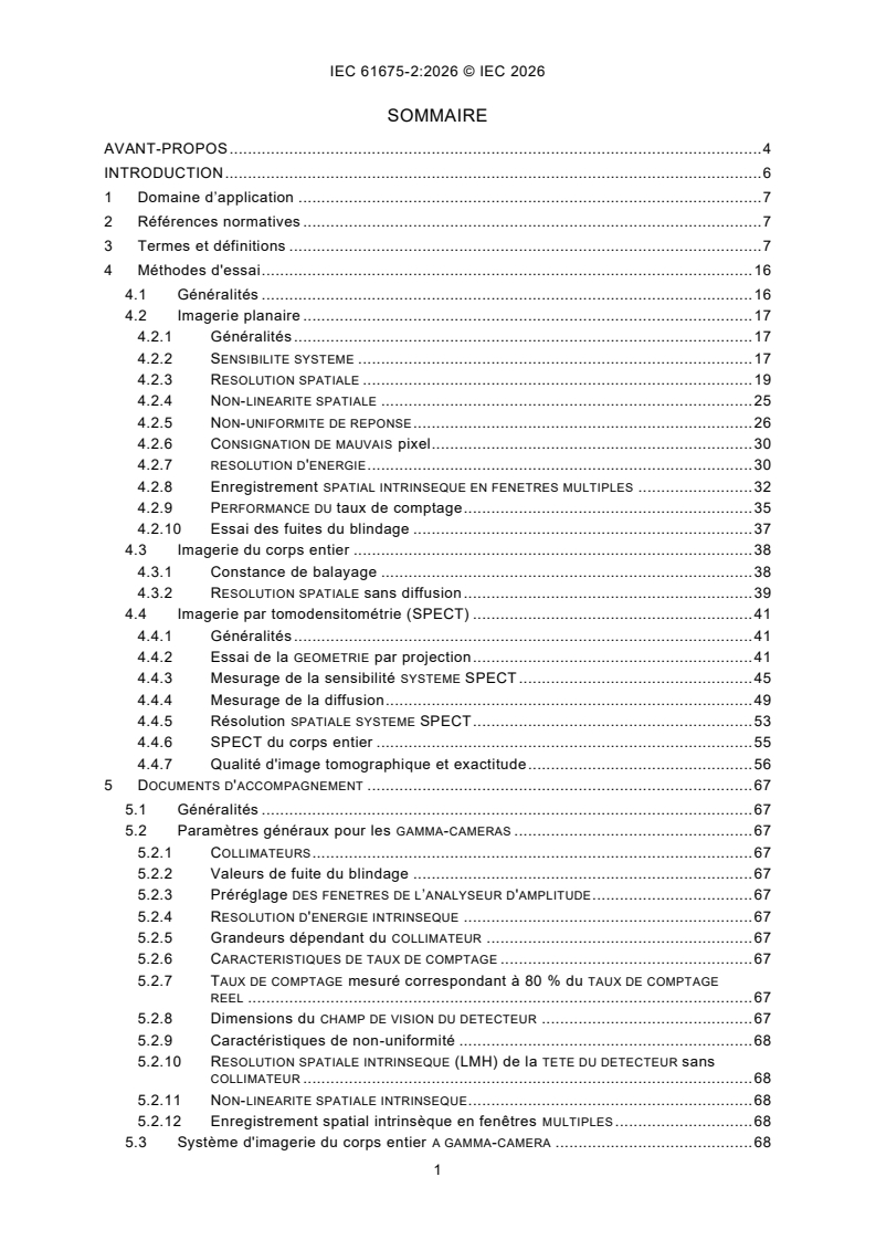
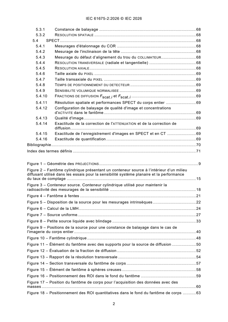
IEC 61675-2:2026 - Dispositifs d'imagerie par radionucléides - Caractéristiques et conditions d'essai - Partie 2: Gamma-caméras pour l'imagerie planaire, l'imagerie du corps entier et l'imagerie SPECT

iec61675-2{ed3.0}en - Radionuclide imaging devices - Characteristics and test conditions - Part 2: Gamma cameras for planar, wholebody, and SPECT imaging
IEC 61675-2:2026 is an IEC International Standard for radionuclide imaging devices, focused on GAMMA CAMERAS with PARALLEL HOLE COLLIMATORS. It specifies terminology and test methods for describing planar imaging, PLANAR WHOLEBODY IMAGING EQUIPMENT, and SINGLE PHOTON EMISSION COMPUTED TOMOGRAPHY (SPECT), including SPECT systems that may also use CT for hybrid imaging.
What does IEC 61675-2:2026 specify?
IEC 61675-2:2026 specifies what to measure, how to measure it, and what to report for GAMMA CAMERAS used in planar, wholebody, and SPECT imaging. It is written for systems built around a gantry, one or more DETECTOR HEADS, and a computer for acquisition, processing, storage, and display.
The document is organized into five clauses:
- Clause 1 - Scope
- Clause 2 - Normative references
- Clause 3 - Terms and definitions
- Clause 4 - Test methods
- Clause 5 - Accompanying documents
Its scope is limited to GAMMA CAMERAS equipped with PARALLEL HOLE COLLIMATORS that can do planar imaging. It also covers additional tests for systems that can do SPECT, planar wholebody imaging, or SPECT wholebody imaging. Novel camera designs with multiple DETECTOR HEADS that are not capable of planar acquisition are outside the scope.
The standard also notes that no test is specified for the uniformity of reconstructed images, because the known methods would mainly reflect image noise. In practice, that means the document concentrates on measurable acquisition and reconstruction characteristics that can be compared from one system to another.
What are the key requirements of IEC 61675-2:2026?
IEC 61675-2:2026 sets a common test framework so that measurements are taken under comparable conditions. The most important requirements are in Clause 4, supported by the reporting items in Clause 5.
Use the specified measurement setup and radionuclides. Clause 4.1 requires all measurements to use the PULSE AMPLITUDE ANALYSER WINDOW settings given in Table 1, with the listed radionuclides and ENERGY WINDOW settings for performance measurements. In practice, this keeps results comparable across systems and labs, and any deviation from the specified test conditions has to be stated clearly.
Characterize each DETECTOR HEAD as a full data set. Clause 4.1 says each DETECTOR HEAD in the system shall be characterized separately. For non-pixelated detectors, the full data set does not include BAD PIXEL measurements or LOW-ENERGY-TAIL RATIO measurements. Practically, this means each head must be assessed on its own performance, and pixel-related checks are only relevant where the detector design supports them.
Use clinical correction settings for planar imaging. Clause 4.1 requires planar imaging characterization to be provided for data acquired with the corrections used in clinical practice. This matters because the reported performance should reflect how the camera is actually used, not just an idealized laboratory setup.
Use the clinically relevant SPECT acquisition geometry. Clause 4.1 says SPECT characterization shall be provided for an acquisition covering the minimal rotation required to obtain a complete set of data. If the tomograph operates in a non-circular orbiting mode that affects performance, those results shall also be reported. In practice, this ensures the test reflects the way the system reconstructs tomographic data in real use.
Measure the main planar performance characteristics. Clause 4.2 covers SYSTEM SENSITIVITY, SPATIAL RESOLUTION, SPATIAL NON-LINEARITY, NON-UNIFORMITY OF RESPONSE, BAD PIXEL reporting, INTRINSIC ENERGY RESOLUTION, Intrinsic MULTIPLE WINDOW SPATIAL REGISTRATION, COUNT RATE performance, and shield leakage. These tests show how well the camera detects counts, preserves position accuracy, handles energy discrimination, and limits unwanted leakage.
Check wholebody imaging stability and resolution. Clause 4.3 covers scanning constancy and SPATIAL RESOLUTION without scatter for PLANAR WHOLEBODY IMAGING EQUIPMENT. This is important because wholebody studies depend on motion during acquisition, so the system must remain consistent along the scan path.
Assess SPECT geometry, sensitivity, scatter, and resolution. Clause 4.4 includes tests of PROJECTION geometry, SPECT SYSTEM SENSITIVITY, scatter measurement, SPECT SYSTEM SPATIAL RESOLUTION, Wholebody SPECT, and tomographic image quality and accuracy. These tests matter because SPECT performance depends on rotation geometry, detector alignment, scatter handling, and how accurately the system reconstructs activity distribution.
Report image quality and correction accuracy, including SPECT/CT alignment. Clause 4.4.7 extends the evaluation to tomographic image quality, attenuation correction, scatter correction, SPECT and CT image registration, and quantitative accuracy. In practice, this is the part that shows whether the reconstructed image supports reliable diagnosis and quantitation, especially for hybrid SPECT/CT systems.
Clause 5 then turns the test results into a documentation set that accompanies each GAMMA CAMERA for planar imaging, PLANAR WHOLEBODY IMAGING EQUIPMENT, and SPECT. That document is expected to summarize the system’s key parameters, performance values, and SPECT-specific results.
What terms does IEC 61675-2:2026 define?
CENTRE OF ROTATION (COR) - The reference origin that describes the PROJECTIONS of a transverse slice in space; for rotating systems, it is tied to the system geometry used in reconstruction.
DETECTOR FIELD OF VIEW (FOV) - The detector region for which events are included in the display image and for which performance specifications are given; this is the active area used when judging performance.
DETECTOR HEAD - The assembly of the radiation detector, COLLIMATOR, and DETECTOR SHIELD; in practice, this is the unit whose imaging performance is characterized.
INTRINSIC ENERGY RESOLUTION - The FULL WIDTH AT HALF MAXIMUM of the full-energy absorption peak in the INTRINSIC ENERGY SPECTRUM for a specified radionuclide; it shows how well the detector separates gamma-ray energies.
NORMALIZED VOLUME SENSITIVITY - The VOLUME SENSITIVITY divided by the AXIAL FIELD OF VIEW of the tomograph or the phantom length, whichever is smaller; this gives a size-normalized sensitivity value for tomographic systems.
SCATTER FRACTION (SF) - The ratio of scattered photons to all photons counted in a defined setup with a specific ENERGY WINDOW and scattering medium; it indicates how much scatter is present under test conditions.
SYSTEM SENSITIVITY - The ratio of DETECTOR HEAD count rate to source ACTIVITY for a defined source, COLLIMATOR, and ENERGY WINDOW under specified conditions; this is one of the main measures of how efficiently the camera detects activity.
Who uses IEC 61675-2:2026?
IEC 61675-2:2026 is used by manufacturers of GAMMA CAMERAS, especially when they need to describe performance for planar, wholebody, and SPECT systems in a consistent way. It is also used by test laboratories and service organizations that carry out performance measurements on installed units.
Medical physicists, nuclear medicine teams, and hospital quality groups use it to compare detector heads, collimators, count rate behavior, spatial resolution, sensitivity, and SPECT image quality. Buyers and technical evaluators use the accompanying documents and test results to compare systems and to understand what performance data the supplier is reporting.
What changed in IEC 61675-2:2026 from the previous edition?
IEC 61675-2:2026 cancels and replaces the second edition published in 2015. The edition states these significant technical changes:
- addition of systems based on pixelated semi-conductor detectors
- addition of tests for wholebody SPECT performance and quantitative SPECT image accuracy
- alignment with NEMA NU 1-2018
- deletion of tests for SPECT-systems operated in coincidence mode because of the lack of market share of these systems
Which standards are used with IEC 61675-2:2026?
IEC TR 60788:2004 - Provides the general glossary of defined terms used across medical electrical equipment and contributes several base definitions used in this document.
IEC 61675-1:2022 - Provides shared radionuclide imaging terminology and related nuclear medicine definitions that IEC 61675-2:2026 reuses for tomography and detector performance terms.
IEC 63073-1:2020 - Provides dedicated radionuclide imaging terminology for cardiac SPECT and contributes several definitions reused or adapted here, including terms used in detector and image-quality descriptions.
What does the IEC 61675-2:2026 document contain?
IEC 61675-2:2026 contains detailed test methods for planar imaging, wholebody imaging, and SPECT, with each method split into purpose, setup, data collection, data processing, data analysis, and report steps. It includes the geometry and phantom arrangements needed for projection tests, sensitivity measurements, scatter measurements, and resolution checks.
The document also includes formulas and calculation steps for performance values such as count rate characterization, detector positioning time correction, scatter-related quantities, and quantitative image accuracy. Figure 1 explains the geometry of PROJECTIONS, and Figure 2 shows the cylindrical phantom used for planar sensitivity and count rate performance.
Clause 5 lists the information that shall accompany the GAMMA CAMERA, including COLLIMATORS, shield leakage values, preset window settings, intrinsic resolution values, count rate characteristics, detector field of view dimensions, wholebody performance, and SPECT-specific results such as COR calibration, head tilt, hole misalignment, axial and transaxial pixel size, scatter fractions, image quality, registration accuracy, and quantitation.
Relations
- Effective Date
- 05-Sep-2023
Buy Documents
REDLINE IEC 61675-2:2026 RLV - Radionuclide imaging devices - Characteristics and test conditions - Part 2: Gamma cameras for planar, wholebody, and SPECT imaging
IEC 61675-2:2026 - Dispositifs d'imagerie par radionucléides - Caractéristiques et conditions d'essai - Partie 2: Gamma-caméras pour l'imagerie planaire, l'imagerie du corps entier et l'imagerie SPECT
iec61675-2{ed3.0}en - Radionuclide imaging devices - Characteristics and test conditions - Part 2: Gamma cameras for planar, wholebody, and SPECT imaging
Get Certified
Connect with accredited certification bodies for this standard

BSI Group
BSI (British Standards Institution) is the business standards company that helps organizations make excellence a habit.

TÜV Rheinland
TÜV Rheinland is a leading international provider of technical services.

TÜV SÜD
TÜV SÜD is a trusted partner of choice for safety, security and sustainability solutions.
Sponsored listings
Frequently Asked Questions
IEC 61675-2:2026 is a standard published by the International Electrotechnical Commission (IEC). Its full title is "Radionuclide imaging devices - Characteristics and test conditions - Part 2: Gamma cameras for planar, wholebody, and SPECT imaging". This standard covers: IEC 61675-2:2026 specifies terminology and test methods for describing the characteristics of GAMMA CAMERAS equipped with PARALLEL HOLE COLLIMATORS that are capable of planar imaging. Additional tests are specified for those GAMMA CAMERAS that are capable of SINGLE PHOTON EMISSION COMPUTED TOMOGRAPHY (SPECT) or planar wholebody imaging (PLANAR WHOLEBODY IMAGING EQUIPMENT) or SPECT wholebody imaging. SPECT systems can also be equipped with a CT system for hybrid imaging. These GAMMA CAMERAS consist of a gantry, single or multiple DETECTOR HEADS, and a computer for data acquisition, processing, storage, and display. The DETECTOR HEADS can contain single or multiple scintillation crystals or solid state detectors. Novel camera designs with multiple DETECTOR HEADS that are not capable of planar acquisition are not included in the scope of this document. IEC 61675-2:2026 cancels and replaces the second edition published in 2015. This edition constitutes a technical revision. This edition includes the following significant technical changes with respect to the previous edition: a) addition of systems based on pixelated semi-conductor detectors; b) addition of tests for wholebody SPECT performance and quantitative SPECT image accuracy; c) alignment with NEMA NU 1-2018; d) deletion of tests for SPECT-systems operated in coincidence mode due to the lack of market share of these systems.
IEC 61675-2:2026 specifies terminology and test methods for describing the characteristics of GAMMA CAMERAS equipped with PARALLEL HOLE COLLIMATORS that are capable of planar imaging. Additional tests are specified for those GAMMA CAMERAS that are capable of SINGLE PHOTON EMISSION COMPUTED TOMOGRAPHY (SPECT) or planar wholebody imaging (PLANAR WHOLEBODY IMAGING EQUIPMENT) or SPECT wholebody imaging. SPECT systems can also be equipped with a CT system for hybrid imaging. These GAMMA CAMERAS consist of a gantry, single or multiple DETECTOR HEADS, and a computer for data acquisition, processing, storage, and display. The DETECTOR HEADS can contain single or multiple scintillation crystals or solid state detectors. Novel camera designs with multiple DETECTOR HEADS that are not capable of planar acquisition are not included in the scope of this document. IEC 61675-2:2026 cancels and replaces the second edition published in 2015. This edition constitutes a technical revision. This edition includes the following significant technical changes with respect to the previous edition: a) addition of systems based on pixelated semi-conductor detectors; b) addition of tests for wholebody SPECT performance and quantitative SPECT image accuracy; c) alignment with NEMA NU 1-2018; d) deletion of tests for SPECT-systems operated in coincidence mode due to the lack of market share of these systems.
IEC 61675-2:2026 is classified under the following ICS (International Classification for Standards) categories: 11.040.50 - Radiographic equipment. The ICS classification helps identify the subject area and facilitates finding related standards.
IEC 61675-2:2026 has the following relationships with other standards: It is inter standard links to IEC 61675-2:2015. Understanding these relationships helps ensure you are using the most current and applicable version of the standard.
IEC 61675-2:2026 is available in PDF format for immediate download after purchase. The document can be added to your cart and obtained through the secure checkout process. Digital delivery ensures instant access to the complete standard document.
Standards Content (Sample)
IEC 61675-2 ®
Edition 3.0 2026-11
INTERNATIONAL
STANDARD
REDLINE VERSION
Radionuclide imaging devices - Characteristics and test conditions -
Part 2: Gamma cameras for planar, wholebody, and SPECT imaging
ICS 11.040.50 ISBN 978-2-8327-1625-0
All rights reserved. Unless otherwise specified, no part of this publication may be reproduced or utilized in any form or
by any means, electronic or mechanical, including photocopying and microfilm, without permission in writing from either
IEC or IEC's member National Committee in the country of the requester. If you have any questions about IEC copyright
or have an enquiry about obtaining additional rights to this publication, please contact the address below or your local
IEC member National Committee for further information.
IEC Secretariat Tel.: +41 22 919 02 11
3, rue de Varembé info@iec.ch
CH-1211 Geneva 20 www.iec.ch
Switzerland
About the IEC
The International Electrotechnical Commission (IEC) is the leading global organization that prepares and publishes
International Standards for all electrical, electronic and related technologies.
About IEC publications
The technical content of IEC publications is kept under constant review by the IEC. Please make sure that you have the
latest edition, a corrigendum or an amendment might have been published.
IEC publications search - IEC Products & Services Portal - products.iec.ch
webstore.iec.ch/advsearchform Discover our powerful search engine and read freely all the
The advanced search enables to find IEC publications by a publications previews, graphical symbols and the glossary.
variety of criteria (reference number, text, technical With a subscription you will always have access to up to date
committee, …). It also gives information on projects, content tailored to your needs.
replaced and withdrawn publications.
Electropedia - www.electropedia.org
The world's leading online dictionary on electrotechnology,
IEC Just Published - webstore.iec.ch/justpublished
Stay up to date on all new IEC publications. Just Published containing more than 22 500 terminological entries in English
details all new publications released. Available online and and French, with equivalent terms in 25 additional languages.
once a month by email. Also known as the International Electrotechnical Vocabulary
(IEV) online.
IEC Customer Service Centre - webstore.iec.ch/csc
If you wish to give us your feedback on this publication or
need further assistance, please contact the Customer
Service Centre: sales@iec.ch.
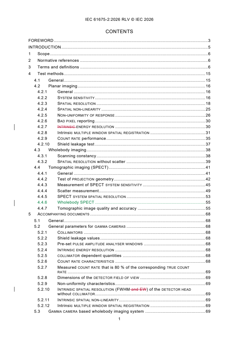
CONTENTS
FOREWORD . 3
INTRODUCTION . 5
1 Scope . 6
2 Normative references . 6
3 Terms and definitions . 6
4 Test methods . 15
4.1 General . 15
4.2 Planar imaging . 16
4.2.1 General . 16
4.2.2 SYSTEM SENSITIVITY . 16
4.2.3 SPATIAL RESOLUTION . 18
4.2.4 SPATIAL NON-LINEARITY . 25
4.2.5 NON-UNIFORMITY OF RESPONSE . 26
4.2.6 BAD PIXEL reporting . 30
4.2.7 INTRINSIC ENERGY RESOLUTION . 30
4.2.8 Intrinsic MULTIPLE WINDOW SPATIAL REGISTRATION . 31
4.2.9 COUNT RATE performance . 35
4.2.10 Shield leakage test . 37
4.3 Wholebody imaging. 38
4.3.1 Scanning constancy . 38
4.3.2 SPATIAL RESOLUTION without scatter . 39
4.4 Tomographic imaging (SPECT) . 41
4.4.1 General . 41
4.4.2 Test of PROJECTION geometry . 42
4.4.3 Measurement of SPECT SYSTEM SENSITIVITY . 45
4.4.4 Scatter measurement. 49
4.4.5 SPECT SYSTEM SPATIAL RESOLUTION . 53
4.4.6 Wholebody SPECT . 55
4.4.7 Tomographic image quality and accuracy . 55
5 ACCOMPANYING DOCUMENTS . 68
5.1 General . 68
5.2 General parameters for GAMMA CAMERAS . 68
5.2.1 COLLIMATORS . 68
5.2.2 Shield leakage values . 68
5.2.3 Pre-set PULSE AMPLITUDE ANALYSER WINDOWS . 68
5.2.4 INTRINSIC ENERGY RESOLUTION . 68
5.2.5 COLLIMATOR dependent quantities . 68
5.2.6 COUNT RATE CHARACTERISTICS . 68
5.2.7 Measured COUNT RATE that is 80 % of the corresponding TRUE COUNT
RATE . 69
5.2.8 Dimensions of the DETECTOR FIELD OF VIEW . 69
5.2.9 Non-uniformity characteristics . 69
5.2.10 INTRINSIC SPATIAL RESOLUTION (FWHM and EW) of the DETECTOR HEAD
without COLLIMATOR . 69
5.2.11 INTRINSIC SPATIAL NON-LINEARITY . 69
5.2.12 Intrinsic MULTIPLE WINDOW SPATIAL REGISTRATION . 69
5.3 GAMMA CAMERA based wholebody imaging system . 69
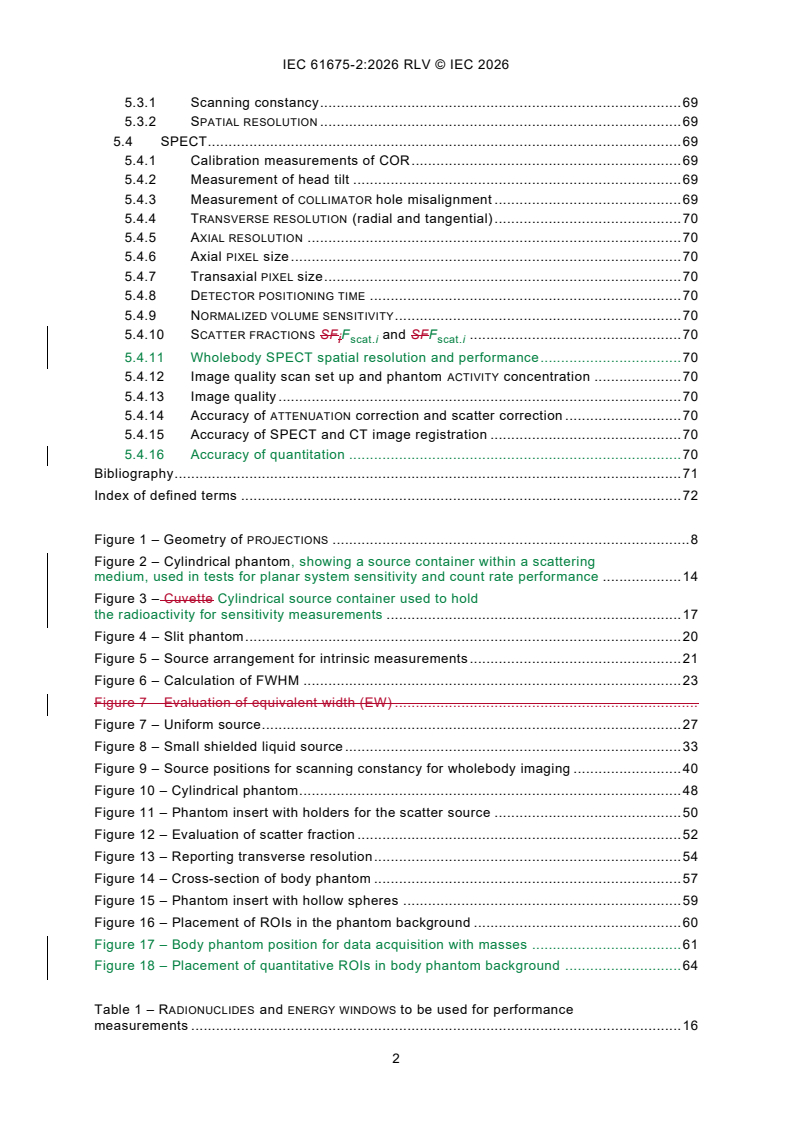
5.3.1 Scanning constancy . 69
5.3.2 SPATIAL RESOLUTION . 69
5.4 SPECT. 69
5.4.1 Calibration measurements of COR . 69
5.4.2 Measurement of head tilt . 69
5.4.3 Measurement of COLLIMATOR hole misalignment . 69
5.4.4 TRANSVERSE RESOLUTION (radial and tangential) . 70
5.4.5 AXIAL RESOLUTION . 70
5.4.6 Axial PIXEL size . 70
5.4.7 Transaxial PIXEL size . 70
5.4.8 DETECTOR POSITIONING TIME . 70
5.4.9 NORMALIZED VOLUME SENSITIVITY . 70
5.4.10 SCATTER FRACTIONS SF F and SFF . 70
i scat.i scat.i
5.4.11 Wholebody SPECT spatial resolution and performance. 70
5.4.12 Image quality scan set up and phantom ACTIVITY concentration . 70
5.4.13 Image quality . 70
5.4.14 Accuracy of ATTENUATION correction and scatter correction . 70
5.4.15 Accuracy of SPECT and CT image registration . 70
5.4.16 Accuracy of quantitation . 70
Bibliography . 71
Index of defined terms . 72
Figure 1 – Geometry of PROJECTIONS . 8
Figure 2 – Cylindrical phantom, showing a source container within a scattering
medium, used in tests for planar system sensitivity and count rate performance . 14
Figure 3 – Cuvette Cylindrical source container used to hold
the radioactivity for sensitivity measurements . 17
Figure 4 – Slit phantom . 20
Figure 5 – Source arrangement for intrinsic measurements . 21
Figure 6 – Calculation of FWHM . 23
Figure 7 – Evaluation of equivalent width (EW) .
Figure 7 – Uniform source. 27
Figure 8 – Small shielded liquid source . 33
Figure 9 – Source positions for scanning constancy for wholebody imaging . 40
Figure 10 – Cylindrical phantom . 48
Figure 11 – Phantom insert with holders for the scatter source . 50
Figure 12 – Evaluation of scatter fraction . 52
Figure 13 – Reporting transverse resolution . 54
Figure 14 – Cross-section of body phantom . 57
Figure 15 – Phantom insert with hollow spheres . 59
Figure 16 – Placement of ROIs in the phantom background . 60
Figure 17 – Body phantom position for data acquisition with masses . 61
Figure 18 – Placement of quantitative ROIs in body phantom background . 64
Table 1 – RADIONUCLIDES and ENERGY WINDOWS to be used for performance
measurements . 16
INTERNATIONAL ELECTROTECHNICAL COMMISSION
____________
Radionuclide imaging devices -
Characteristics and test conditions -
Part 2: Gamma cameras for planar, wholebody, and SPECT imaging
FOREWORD
1) The International Electrotechnical Commission (IEC) is a worldwide organization for standardization comprising
all national electrotechnical committees (IEC National Committees). The object of IEC is to promote international
co-operation on all questions concerning standardization in the electrical and electronic fields. To this end and
in addition to other activities, IEC publishes International Standards, Technical Specifications, Technical Reports,
Publicly Available Specifications (PAS) and Guides (hereafter referred to as “IEC Publication(s)”). Their
preparation is entrusted to technical committees; any IEC National Committee interested in the subject dealt with
may participate in this preparatory work. International, governmental and non-governmental organizations liaising
with the IEC also participate in this preparation. IEC collaborates closely with the International Organization for
Standardization (ISO) in accordance with conditions determined by agreement between the two organizations.
2) The formal decisions or agreements of IEC on technical matters express, as nearly as possible, an international
consensus of opinion on the relevant subjects since each technical committee has representation from all
interested IEC National Committees.
3) IEC Publications have the form of recommendations for international use and are accepted by IEC National
Committees in that sense. While all reasonable efforts are made to ensure that the technical content of IEC
Publications is accurate, IEC cannot be held responsible for the way in which they are used or for any
misinterpretation by any end user.
4) In order to promote international uniformity, IEC National Committees undertake to apply IEC Publications
transparently to the maximum extent possible in their national and regional publications. Any divergence between
any IEC Publication and the corresponding national or regional publication shall be clearly indicated in the latter.
5) IEC itself does not provide any attestation of conformity. Independent certification bodies provide conformity
assessment services and, in some areas, access to IEC marks of conformity. IEC is not responsible for any
services carried out by independent certification bodies.
6) All users should ensure that they have the latest edition of this publication.
7) No liability shall attach to IEC or its directors, employees, servants or agents including individual experts and
members of its technical committees and IEC National Committees for any personal injury, property damage or
other damage of any nature whatsoever, whether direct or indirect, or for costs (including legal fees) and
expenses arising out of the publication, use of, or reliance upon, this IEC Publication or any other IEC
Publications.
8) Attention is drawn to the Normative references cited in this publication. Use of the referenced publications is
indispensable for the correct application of this publication.
9) IEC draws attention to the possibility that the implementation of this document may involve the use of (a)
patent(s). IEC takes no position concerning the evidence, validity or applicability of any claimed patent rights in
respect thereof. As of the date of publication of this document, IEC had not received notice of (a) patent(s), which
may be required to implement this document. However, implementers are cautioned that this may not represent
the latest information, which may be obtained from the patent database available at https://patents.iec.ch. IEC
shall not be held responsible for identifying any or all such patent rights.
This redline version of the official IEC Standard allows users to identify the changes made since
the previous edition, IEC 61675-2:2015. A vertical bar appears in the margin wherever a change
has been made. Additions are shown in green text, and deletions are shown in red strikethrough
text.
IEC 61675-2 has been prepared by subcommittee 62C: Equipment for radiotherapy, nuclear
medicine and radiation dosimetry, of IEC technical committee 62: Medical equipment, software,
and systems. It is an International Standard.
This third edition cancels and replaces the second edition published in 2015. This edition
constitutes a technical revision.
This edition includes the following significant technical changes with respect to the previous
edition:
a) addition of systems based on pixelated semi-conductor detectors;
b) addition of tests for wholebody SPECT performance and quantitative SPECT image
accuracy;
c) alignment with NEMA NU 1-2018;
d) deletion of tests for SPECT-systems operated in coincidence mode due to the lack of market
share of these systems.
The text of this International Standard is based on the following documents:
Draft Report on voting
62C/990/FDIS 62C/998/RVD
Full information on the voting for its approval can be found in the report on voting indicated in
the above table.
The language used for the development of this International Standard is English.
This document was drafted in accordance with ISO/IEC Directives, Part 2, and developed in
accordance with ISO/IEC Directives, Part 1 and ISO/IEC Directives, IEC Supplement, available
at www.iec.ch/members_experts/refdocs. The main document types developed by IEC are
described in greater detail at www.iec.ch/publications.
In this document, the following print types are used:
– terms defined in Clause 0 of this document or listed in the index of defined terms: SMALL
CAPITALS.
The requirements are followed by specifications for the relevant tests.
A list of all parts in the IEC 61675 series, published under the general title Radionuclide imaging
devices - Characteristics and test conditions, can be found on the IEC website.
The committee has decided that the contents of this document will remain unchanged until the
stability date indicated on the IEC website under webstore.iec.ch in the data related to the
specific document. At this date, the document will be
– reconfirmed,
– withdrawn, or
– revised.
INTRODUCTION
The test methods specified in this document have been selected to reflect as much as possible
the clinical use of GAMMA CAMERAS for planar imaging, PLANAR WHOLEBODY IMAGING EQUIPMENT,
and SINGLE PHOTON EMISSION COMPUTED TOMOGRAPHY (SPECT). It is intended that the test
methods are carried out by manufacturers thereby enabling them to describe the characteristics
of the systems on a common basis.
This document combines IEC 60789:1992, IEC 61675-2:1998, IEC 61675-2:1998/AMD1:2004,
and IEC 61675-3:1998 .
___________
These publications have been withdrawn.
1 Scope
This part of IEC 61675 specifies terminology and test methods for describing the characteristics
of GAMMA CAMERAS equipped with PARALLEL HOLE COLLIMATORS for that are capable of planar
imaging. Additional tests are specified for those GAMMA CAMERAS that are capable of SINGLE
PHOTON EMISSION COMPUTED TOMOGRAPHY (SPECT) or planar wholebody imaging (PLANAR
WHOLEBODY IMAGING EQUIPMENT) or SPECT wholebody imaging. SPECT systems can also be
equipped with a CT system for hybrid imaging.
These GAMMA CAMERAS consist of a gantry, single or multiple DETECTOR HEADS, and a computer
for data acquisition, processing, storage, and display. The DETECTOR HEADS may can contain
single or multiple scintillation crystals or solid state detectors.
No test has been specified to characterize the uniformity of reconstructed images because all
methods known so far will mostly reflect the noise of the image.
Novel camera designs with multiple DETECTOR HEADS that are not capable of planar acquisition
are not included in the scope of this document.
2 Normative references
The following documents are referred to in the text in such a way that some or all of their content
constitutes requirements of this document. For dated references, only the edition cited applies.
For undated references, the latest edition of the referenced document (including any
amendments) applies.
IEC TR 60788:2004, Medical electrical equipment - Glossary of defined terms
IEC 61675-1:20132022, Radionuclide imaging devices - Characteristics and test conditions -
Part 1: Positron emission tomographs
IEC 63073-1:2020, Dedicated radionuclide imaging devices - Characteristics and test
conditions - Part 1: Cardiac SPECT
3 Terms and definitions
For the purposes of this document the terms and definitions given in IEC TR 60788:2004,
IEC 63073-1:2020 and IEC 61675-1:2022, and the following terms and definitions apply.
ISO and IEC maintain terminology databases for use in standardization at the following
addresses:
– IEC Electropedia: available at https://www.electropedia.org/
– ISO Online browsing platform: available at https://www.iso.org/obp
3.1
ADDRESS PILE UP
false address calculation of an artificial event which passes the ENERGY
WINDOW, but is formed from two or more events by the PILE UP EFFECT
3.2
AXIAL FIELD OF VIEW
dimensions of a slice through the TOMOGRAPHIC VOLUME parallel to and including the SYSTEM
AXIS
Note 1 to entry: In practice it is specified only by its axial dimension given by the distance between the centres of
the outermost defined IMAGE PLANES plus the average of the measured AXIAL SLICE WIDTH measured as EQUIVALENT
WIDTH (EW).
3.3
AXIAL RESOLUTION
SPATIAL
RESOLUTION along a line parallel to the SYSTEM AXIS
3.4
BAD PIXEL
detector pixel within the DETECTOR FIELD OF VIEW of the detector that has been physically or
electronically turned off such that gamma rays which interact in that pixel are not recorded by
the camera
[SOURCE: IEC 63073-1:2020, 3.2, modified – The words "within the DETECTOR FIELD OF VIEW of
the detector" have been added, and "in that BAD PIXEL" have been replaced with " in that pixel".]
3.5
CENTRE OF ROTATION
COR
origin of that coordinate system, which describes the PROJECTIONS of a transverse slice with
respect to their orientation in space
Note 1 to entry: The CENTRE OF ROTATION of a transverse slice is given by the intersection of the SYSTEM AXIS with
the mid-plane of the corresponding OBJECT SLICE.
Note 2 to entry: The second note to entry concerns the French text only.
3.6
COLLIMATOR
block of radiation attenuating material with one or more
apertures defining the field of view and limiting the angular spread of the RADIATION that can
reach the RADIATION DETECTOR ASSEMBLY
[SOURCE: IEC TR 60788:2004, rm-34-05]
3.7
COLLIMATOR AXIS
straight line which passes through the geometrical centre of the exit field and ENTRANCE FIELD
of the COLLIMATOR
3.8
COLLIMATOR FRONT FACE
surface of the COLLIMATOR which is closest to the object being imaged
3.9
COORDINATE SYSTEM OF PROJECTION
Cartesian system of the IMAGE MATRIX of each two-dimensional PROJECTION with axes X and
p
Y
p
Note 1 to entry: Axes X and Y are defined by the axes of the IMAGE MATRIX.
p p
Note 2 to entry: The Y axis and the PROJECTION of the SYSTEM AXIS onto the detector COLLIMATOR FRONT FACE have
p
to shall be in parallel.
Note 3 to entry: The origin of the COORDINATE SYSTEM OF PROJECTION may can be the centre of the IMAGE MATRIX
(see Figure 1).
NOTE The FIXED COORDINATE SYSTEM X, Y, Z has its origin at the centre of the TOMOGRAPHIC VOLUME (shown as a
cylinder), the Z-axis being the SYSTEM AXIS. The COORDINATE SYSTEM OF PROJECTION X , Y is shown for a PROJECTION
p p
ANGLE . For each , the one-dimensional PROJECTION of the marked OBJECT SLICE has the address range shown
(hatched). Within this range the CENTRE OF ROTATION is projected onto the address X’ (offset).
p
Figure 1 – Geometry of PROJECTIONS
3.10
COUNT LOSS
difference between measured COUNT RATE and TRUE COUNT RATE, which is caused by the finite
RESOLVING TIME of the instrument
[SOURCE: IEC 61675-1:20132022, 3.8.1]
3.11
COUNT RATE
number of counts per unit of time
[SOURCE: IEC 61675-1:20132022, 3.8.2]
3.12
COUNT RATE CHARACTERISTIC
function giving the relationship between observed COUNT RATE and TRUE COUNT RATE
[SOURCE: IEC TR 60788:2004, rm-34-21]
3.13
DETECTOR FIELD OF VIEW
FOV
region of the detector within which events are included in the display image, and for which all
performance specifications are provided
Note 1 to entry: The note to entry regarding the abbreviation concerns the French text only.
3.14
DETECTOR HEAD
assembly of the RADIATION DETECTOR assembly, the COLLIMATOR and the DETECTOR SHIELD.
[SOURCE: IEC TR 60788:2004, rm-34-09]
3.15
DETECTOR HEAD TILT
deviation of the COLLIMATOR AXIS from orthogonality with the SYSTEM AXIS
3.16
DETECTOR POSITIONING TIME
fraction of the total time spent on an acquisition which is not used in collecting data
3.17
DETECTOR PIXEL
smallest discrete unit of a pixelated DETECTOR HEAD that is able to provide distinct energy,
spatial, and timing information about detected photons
3.18
EMISSION COMPUTED TOMOGRAPHY
ECT
imaging method for the representation of the spatial distribution of RADIONUCLIDES in selected
two-dimensional slices through the object
3.19
ENERGY WINDOW
range defining the energy of the signals accepted by the device for further processing
3.20
ENTRANCE FIELD
area on the entrance face bounded by the shortest perimeter tangential to the
outside edges of the peripheral apertures on its entrance face
[SOURCE: IEC TR 60788:2004, rm-34-12]
3.21
EQUIVALENT WIDTH
EW
width of that rectangle having the same area and the same height as the response function,
e.g., the POINT SPREAD FUNCTION
[SOURCE: IEC TR 60788:2004, rm-34-45]
3.22
FIXED COORDINATE SYSTEM
Cartesian system with axes X, Y, and Z
Note 1 to entry: Z is the SYSTEM AXIS.
Note 2 to entry: The origin of the FIXED COORDINATE SYSTEM is defined by the centre of the TOMOGRAPHIC VOLUME
(see Figure 1).
Note 3 to entry: The SYSTEM AXIS is orthogonal to all transverse slices.
3.23
IMAGE MATRIX
arrangement of MATRIX ELEMENTS in a preferentially Cartesian coordinate system
[SOURCE: IEC TR 60788:2004, rm-32-55]
3.24
IMAGE PLANE
plane assigned to a plane in the OBJECT SLICE
Note 1 to entry: Usually the IMAGE PLANE is the mid-plane of the corresponding OBJECT SLICE.
3.25
INTRINSIC ENERGY RESOLUTION
FULL WIDTH AT HALF MAXIMUM of the full energy ABSORPTION peak in the INTRINSIC ENERGY
SPECTRUM for a specified RADIONUCLIDE
3.26
INTRINSIC ENERGY SPECTRUM
measured histogram of PULSE heights for the DETECTOR HEAD without COLLIMATOR
Note 1 to entry: The PULSE height should be expressed as corresponding energy.
3.27
INTRINSIC NON-UNIFORMITY OF RESPONSE
NON-UNIFORMITY OF RESPONSE of the DETECTOR HEAD without COLLIMATOR
3.28
INTRINSIC SPATIAL NON-LINEARITY
SPATIAL NON-LINEARITY of the DETECTOR HEAD without COLLIMATOR
3.29
INTRINSIC SPATIAL RESOLUTION
SPATIAL RESOLUTION in air for a specified RADIONUCLIDE measured without the
COLLIMATOR
3.30
LINE SOURCE
straight RADIOACTIVE SOURCE approximating a -function in two dimensions and being constant
(uniform) in the third dimension
3.31
LOW-ENERGY-TAIL RATIO
ratio of the counts measured in an energy window of width 2 × E centred at energy E
FWHM peak
– 2 × E divided by the counts measured in an energy window of width 2 × E centred
FWHM FWHM
at an energy of E , where E is the peak energy of the RADIOISOTOPE being measured and
peak peak
E is the energy resolution of the detector
FWHM
[SOURCE: IEC 63073-1:2020, 3.12]
3.32
MATRIX ELEMENT
smallest unit of an IMAGE MATRIX, which is assigned in location and size to a certain volume
element of the object (VOXEL)
3.33
MULTIPLE WINDOW SPATIAL REGISTRATION
measured position of a source as a function of the ENERGY WINDOW setting
3.34
NON-UNIFORMITY OF RESPONSE
differences in COUNT RATE between small areas of specified
dimensions within the DETECTOR FIELD OF VIEW when a uniform plane source parallel to the
detector face and of dimensions larger than its ENTRANCE FIELD is used
[SOURCE: IEC TR 60788:2004, rm-34-26]
3.35
NORMALIZED VOLUME SENSITIVITY
VOLUME SENSITIVITY divided by the AXIAL FIELD OF VIEW of the tomograph or the phantom length,
whichever is the smaller
3.36
OBJECT SLICE
slice in the object
Note 1 to entry: The physical property of this slice that determines the measured information is displayed in the
tomographic image.
3.37
OFFSET
deviation of the position of the PROJECTION of the COR (X' ) from X = 0
p p
Note 1 to entry: see Figure 1.
3.38
PARALLEL HOLE COLLIMATOR
COLLIMATOR with a number of apertures, the axes of which are parallel
3.39
PILE UP EFFECT
false measurement of the pulse amplitude, due to the absorption of two or more gamma rays,
reaching the same radiation detector within the RESOLVING TIME
3.40
PIXEL
MATRIX ELEMENT in a two-dimensional IMAGE MATRIX
3.41
PLANAR WHOLEBODY IMAGING EQUIPMENT
GAMMA CAMERA, with one or two DETECTOR HEAD(S), in which the image of an
extended object is formed by moving the DETECTOR HEAD(S) or the object in the axial direction
relative to each other
3.42
POINT SOURCE
RADIOACTIVE SOURCE approximating a -function in all three dimensions
3.43
POINT SPREAD FUNCTION
PSF
scintigraphic image of a POINT SOURCE
3.44
PROJECTION
transformation of a three-dimensional object into its two-dimensional image or of a two-
dimensional object into its one-dimensional image, by integrating the physical property which
determines the image along the direction of the PROJECTION BEAM
Note 1 to entry: The projection process is mathematically described by line integrals in the direction of PROJECTION
and called the Radon-transform.
3.45
PROJECTION ANGLE
angle at which the PROJECTION is measured or acquired
Note 1 to entry: SEE: Figure 1.
3.46
PROJECTION BEAM
smallest possible volume in which the physical property which determines the image is
integrated during the measurement process
Note 1 to entry: The projection beam's shape is limited by the SPATIAL RESOLUTION in all three dimensions and can
vary with photon energy and COLLIMATOR design.
Note 2 to entry: In SPECT, the PROJECTION BEAM usually has the shape of a long thin diverging cone.
3.47
RADIAL RESOLUTION
TRANSVERSE RESOLUTION along a line passing through the position of the source and the SYSTEM
AXIS
[SOURCE: IEC 61675-1:20132022, 3.4.1.1]
3.48
RADIOACTIVE SOURCE
quantity of radioactive material having both an ACTIVITY and a specific ACTIVITY above specific
levels
[SOURCE: IEC TR 60788:2004, rm-20-02]
3.49
RADIUS OF ROTATION
distance between the SYSTEM AXIS and the COLLIMATOR FRONT FACE
3.50
SCATTER FRACTION
SF
ratio between the number of scattered photons and the sum of scattered plus
unscattered photons for a given experimental set-up which includes a specific ENERGY WINDOW
size and position and a specific scattering medium
3.51
SINGLE PHOTON EMISSION COMPUTED TOMOGRAPHY
SPECT
EMISSION COMPUTED TOMOGRAPHY utilizing single photon detection of gamma-ray emitting
RADIONUCLIDES
Note 1 to entry: The note to entry regarding the abbreviation concerns the French version only.
3.52
SINOGRAM
two-dimensional display of all one-dimensional PROJECTIONS of an OBJECT SLICE, as a function
of the PROJECTION ANGLE
Note 1 to entry: The PROJECTION ANGLE is displayed on the ordinate, and the linear PROJECTION coordinate is
displayed on the abscissa.
[SOURCE: IEC 61675-1:20132022, 3.1.21.4]
3.53
SLICE SENSITIVITY
ratio of COUNT RATE as measured on the SINOGRAM to the ACTIVITY concentration in the phantom
Note 1 to entry: In SPECT the measured counts are not numerically corrected for scatter by subtracting the SCATTER
FRACTION.
[SOURCE: IEC 61675-1:20132022, 3.6, modified – The word "PET" has been replaced with
"SPECT" in the note to entry, and "are numerically corrected" was changed to "are not
numerically corrected".]
3.54
SPATIAL NON-LINEARITY
deviation of the image of a straight LINE SOURCE from a straight line
3.55
SPATIAL RESOLUTION
ability to concentrate the count density distribution in the image of a POINT
SOURCE to a point
[SOURCE: IEC 61675-1:20132022, 3.4]
3.56
SYSTEM AXIS
axis of symmetry characterized by geometrical and physical properties of the arrangement of
the system
Note 1 to entry: The SYSTEM AXIS of a GAMMA CAMERA with rotating detectors is the axis of rotation.
[SOURCE: IEC 61675-1:20132022, 3.1.21.7, modified – Note to entry has been adapted to this
document.]
3.57
SYSTEM NON-UNIFORMITY OF RESPONSE
NON-UNIFORMITY OF RESPONSE of the DETECTOR HEAD with COLLIMATOR
3.58
SYSTEM SENSITIVITY
ratio, with a specified COLLIMATOR and ENERGY WINDOW, of the COUNT RATE of
the DETECTOR HEAD to the ACTIVITY of a plane source of specific dimensions and containing a
specified RADIONUCLIDE placed perpendicular to and centred on the COLLIMATOR AXIS under
specified conditions
Note 1 to entry: See Figure 2.
Dimensions in millimetres
NOTE 1 The material is polymethylmethacrylate.
NOTE 2 The hashed area indicates the scattering material.
Figure 2 – Cylindrical phantom, showing a source container within a scattering medium,
used in tests for planar system sensitivity and count rate performance
3.59
SYSTEM SPATIAL RESOLUTION
SPATIAL RESOLUTION in a scattering medium for a specified COLLIMATOR, or
and a specified RADIONUCLIDE, and at a specified distance from the COLLIMATOR FRONT FACE
3.60
TANGENTIAL RESOLUTION
TRANSVERSE RESOLUTION in the direction orthogonal to the direction of RADIAL RESOLUTION
[SOURCE: IEC 61675-1:20132022, 3.4.1.2]
3.61
TOMOGRAPHIC VOLUME
juxtaposition of all volume elements which contribute to the measured PROJECTIONS for all
PROJECTION ANGLES
Note 1 to entry: For a rotating GAMMA CAMERA with a circular field of view, the TOMOGRAPHIC VOLUME is a sphere
provided that the RADIUS OF ROTATION is larger than the radius of the field of view. For a rectangular field of view, the
TOMOGRAPHIC VOLUME is a cylinder.
[SOURCE: IEC 61675-1:20132022, 3.1.21.8, modified – A note to entry has been added.]
3.62
TRANSVERSE POINT SPREAD FUNCTION
reconstructed two-dimensional POINT SPREAD FUNCTION in a tomographic IMAGE PLANE
Note 1 to entry: In TOMOGRAPHY, the TRANSVERSE POINT SPREAD FUNCTION can also be obtained from a LINE SOURCE
located parallel to the SYSTEM AXIS.
[SOURCE: IEC 61675-1:20132022, 3.3.3]
3.63
TRANSVERSE RESOLUTION
SPATIAL RESOLUTION in a reconstructed plane perpendicular to the SYSTEM AXIS
[SOURCE: IEC 61675-1:20132022, 3.4.1]
3.64
VOLUME SENSITIVITY
sum of the individual SLICE SENSITIVITY for all slices in the volume
[SOURCE: IEC 61675-1:20132022, 3.7, modified – Deletion of "individual", and replacement of
“SENSITIVITIES” with “SENSITIVITY for all slices in the volume”.]
3.65
VOXEL
volume element in the object which is assigned to a MATRIX ELEMENT in a two- or three-
dimensional IMAGE MATRIX
Note 1 to entry: The dimensions of the VOXEL are determined by the dimensions of the corresponding MATRIX
ELEMENT via the appropriate scale factors and by the systems SPATIAL RESOLUTION in all three dimensions.
[SOURCE: IEC 61675-1:20132022, 3.2.23]
4 Test methods
4.1 General
All measurements shall be performed with the PULSE AMPLITUDE ANALYSER WINDOW set as
specified in Table 1. Additional measurements with other settings as specified by the
manufacturer can be performed. Before the measurements are performed, the tomographic
system shall be adjusted by the procedure normally used by the manufacturer for an installed
unit and shall not be adjusted specially for the measurement of specific parameters. If any test
cannot be carried out exactly as specified in this document, the reason for the deviation and
the exact conditions under which the test was performed shall be stated clearly.
Table 1 – RADIONUCLIDES and ENERGY WINDOWS to be used for performance measurements
RADIONUCLIDE ENERGY WINDOW
keV
99m
141 (±7,510 %)
Tc
364 (±10 %)
I
93, 184, 300 (±10 %)
Ga
122 (±10 %)
Co
113, 208 (±10 %)
Lu
NOTE Because the characteristics of a GAMMA CAMERA may can change noticeably
57 99m
between 122 keV ( Co) and 141 keV ( Tc), the former is not included as a suitable
RADIONUCLIDE. However, it may can be useful in some circumstances, for example for
177 67
quality control. Lu is included as a possible alternative to Ga for assessing multiple
window spatial registration.
Unless otherwise specified, Each DETECTOR HEAD in the system shall be characterized by a full
data set. For non-pixelated detectors, the full data set does not include BAD PIXEL measurements
(4.2.6) or LOW-ENERGY-TAIL RATIO measurements (4.2.7).
Planar imaging characterization shall be provided for data acquired with those corrections used
in clinical practice.
Unless otherwise specified, SPECT characterization shall be provided for an acquisition
covering the minimal rotation required to obtain a complete set of data (e.g., 120° for a three-
headed system). If the tomograph is specified to operate in a non-circular orbiting mode
influencing the performance parameters, test results for the non-circular orbiting mode shall be
reported in addition. For SPECT characterization, all corrections that are used for clinical
acquisitions are applied unless explicitly stated otherwise.
4.2 Planar imaging
4.2.1 General
Unless otherwise specified For the planar imaging tests, measurements shall be carried out at
COUNT RATES not exceeding 20 000 40 000 counts per second except for the intrinsic multiple
window spatial registration test (4.2.8) which limits COUNT RATES per photopeak ENERGY WINDOW
measured and the count rate performance test (4.2.9) which makes measurements over a range
of COUNT RATES.
4.2.2 SYSTEM SENSITIVITY
4.2.2.1 General
SYSTEM SENSITIVITY is a parameter that characterizes the effectiveness of a system to identify
the radiation emitted from a RADIOACTIVE SOURCE, i.e., the rate at which events are detected in
the presence of a RADIOACTIVE SOURCE with low ACTIVITY where COUNT LOSS is negligible. The
measured COUNT RATE for a given ACTIVITY and RADIONUCLIDE depends on many factors,
including the detector material, its size and thickness, the size and shape of the RADIOACTIVE
SOURCE including its absorption and scatter properties, and instrument’s dead time, energy
thresholds and COLLIMATOR.
4.2.2.2 Purpose
The purpose of this measurement is to determine the detected rate of events per unit of ACTIVITY
for a standard volume source of given dimensions and a specified COLLIMATOR.
4.2.2.3 Method
The SYSTEM SENSITIVITY test places a known amount of ACTIVITY of a specified RADIONUCLIDE
within the DETECTOR FIELD OF VIEW of the GAMMA CAMERA and observes the resulting COUNT RATE.
From these values the SYSTEM SENSITIVITY is calculated. The test is critically dependent upon
accurate assays of ACTIVITY as measured in a dose calibrator or well counter. It is difficult to
maintain an absolute calibration with such devices to accuracies better than 10 %. Absolute
reference standards of the appropriate RADIONUCLIDE should be considered if higher degrees of
accuracy are required. A dose calibrator or well counter that is calibrated according to
manufacturer recommendations shall be used.
4.2.2.4 RADIONUCLIDE
The RADIONUCLIDE used for this measurement shall be appropriate for the COLLIMATOR energy
specification and chosen from Table 1.
4.2.2.5 RADIOACTIVE SOURCE distribution
The cylindrical phantom of polymethylmethacrylate as specified in Figure 2 shall be used. The
source cuvette container shown in Figure 3 shall be filled with the appropriate RADIONUCLIDE
and shall be placed in the cylindrical hole with the dimensions shown in Figure 2; the remainder
of the hole shall then be filled by the cylindrical insert, the dimensions of which are also shown
in Figure 2. The phantom, including the source, shall then be placed on the COLLIMATOR FRONT
FACE (distance d = 0) and centred on the COLLIMATOR AXIS.
Dimensions in millimetres
Material: polymethylmethacrylate.
Figure 3 – Cuvette Cylindrical source container used to hold
the radioactivity for sensitivity measurements
NOTE Measurements of SYSTEM SENSITIVITY without scatter, using the source cuvette container of Figure 3 placed
at a distance of 10 cm from the COLLIMATOR FRONT FACE, may can be carried out in addition to this test.
4.2.2.6 Data collection
With an ENERGY WINDOW setting as specified in Table 1, at least 200 000 counts shall be
acquired, and the data acquisition time recorded to calculate the COUNT RATE, C , for all events
s
collected in the image.
For pixelated detectors, BAD PIXEL correction should not be applied. If BAD PIXEL correction
cannot be deactivated, then this is noted in the report.
4.2.2.7 Data processing
The ACTIVITY in the phantom shall be corrected for decay to determine the average ACTIVITY,
A , during the data acquisition time interval, T , by Formula (1):
ave acq
T
A T T −T
acq
cal 1/2 cal 0
A = exp ln2 1− exp − ln2
(1)
ave
ln2 T T T
acq 1/ 2 1/ 2
where
A is the ACTIVITY measured at time T ;
cal cal
T is the time when the source activity is measured with a dose calibrator or well counter;
cal
T is the acquisition start time;
T is the RADIOACTIVE HALF-LIFE of the RADIONUCLIDE.
1/2
4.2.2.8 Data analysis
The SYSTEM SENSITIVITY S for the COLLIMATOR used shall then be found by
C
s
S=
(2)
A
ave
-1 -1
and shall be expressed in counts s MBq C is the me
...
IEC 61675-2 ®
Édition 3.0 2026-11
NORME
INTERNATIONALE
Dispositifs d'imagerie par radionucléides - Caractéristiques et conditions d'essai -
Partie 2: Gamma-caméras pour l'imagerie planaire, l'imagerie du corps entier et
l'imagerie SPECT
ICS 11.040.50 ISBN 978-2-8327-1601-4
Droits de reproduction réservés. Sauf indication contraire, aucune partie de cette publication ne peut être reproduite ni
utilisée sous quelque forme que ce soit et par aucun procédé, électronique ou mécanique, y compris la photocopie et
les microfilms, sans l'accord écrit de l'IEC ou du Comité national de l'IEC du pays du demandeur. Si vous avez des
questions sur le copyright de l'IEC ou si vous désirez obtenir des droits supplémentaires sur cette publication, utilisez
les coordonnées ci-après ou contactez le Comité national de l'IEC de votre pays de résidence.
IEC Secretariat Tel.: +41 22 919 02 11
3, rue de Varembé info@iec.ch
CH-1211 Geneva 20 www.iec.ch
Switzerland
A propos de l'IEC
La Commission Electrotechnique Internationale (IEC) est la première organisation mondiale qui élabore et publie des
Normes internationales pour tout ce qui a trait à l'électricité, à l'électronique et aux technologies apparentées.
A propos des publications IEC
Le contenu technique des publications IEC est constamment revu. Veuillez vous assurer que vous possédez l’édition la
plus récente, un corrigendum ou amendement peut avoir été publié.
Recherche de publications IEC - IEC Products & Services Portal - products.iec.ch
webstore.iec.ch/advsearchform Découvrez notre puissant moteur de recherche et consultez
La recherche avancée permet de trouver des publications gratuitement tous les aperçus des publications, symboles
IEC en utilisant différents critères (numéro de référence, graphiques et le glossaire. Avec un abonnement, vous aurez
texte, comité d’études, …). Elle donne aussi des toujours accès à un contenu à jour adapté à vos besoins.
informations sur les projets et les publications remplacées
ou retirées. Electropedia - www.electropedia.org
Le premier dictionnaire d'électrotechnologie en ligne au
IEC Just Published - webstore.iec.ch/justpublished monde, avec plus de 22 500 articles terminologiques en
Restez informé sur les nouvelles publications IEC. Just anglais et en français, ainsi que les termes équivalents
dans 25 langues additionnelles. Egalement appelé
Published détaille les nouvelles publications parues.
Disponible en ligne et une fois par mois par email. Vocabulaire Electrotechnique International (IEV) en ligne.
Service Clients - webstore.iec.ch/csc
Si vous désirez nous donner des commentaires sur cette
publication ou si vous avez des questions contactez-
nous: sales@iec.ch.
SOMMAIRE
AVANT-PROPOS . 4
INTRODUCTION . 6
1 Domaine d’application . 7
2 Références normatives . 7
3 Termes et définitions . 7
4 Méthodes d'essai . 16
4.1 Généralités . 16
4.2 Imagerie planaire . 17
4.2.1 Généralités . 17
4.2.2 SENSIBILITE SYSTEME . 17
4.2.3 RESOLUTION SPATIALE . 19
4.2.4 NON-LINEARITE SPATIALE . 25
4.2.5 NON-UNIFORMITE DE REPONSE . 26
4.2.6 CONSIGNATION DE MAUVAIS pixel . 30
4.2.7 RESOLUTION D'ENERGIE . 30
4.2.8 Enregistrement SPATIAL INTRINSEQUE EN FENETRES MULTIPLES . 32
4.2.9 PERFORMANCE DU taux de comptage . 35
4.2.10 Essai des fuites du blindage . 37
4.3 Imagerie du corps entier . 38
4.3.1 Constance de balayage . 38
4.3.2 RESOLUTION SPATIALE sans diffusion . 39
4.4 Imagerie par tomodensitométrie (SPECT) . 41
4.4.1 Généralités . 41
4.4.2 Essai de la GEOMETRIE par projection . 41
4.4.3 Mesurage de la sensibilité SYSTEME SPECT . 45
4.4.4 Mesurage de la diffusion . 49
4.4.5 Résolution SPATIALE SYSTEME SPECT . 53
4.4.6 SPECT du corps entier . 55
4.4.7 Qualité d'image tomographique et exactitude . 56
5 DOCUMENTS D'ACCOMPAGNEMENT . 67
5.1 Généralités . 67
5.2 Paramètres généraux pour les GAMMA-CAMERAS . 67
5.2.1 COLLIMATEURS . 67
5.2.2 Valeurs de fuite du blindage . 67
5.2.3 Préréglage DES FENETRES DE L’ANALYSEUR D'AMPLITUDE . 67
5.2.4 RESOLUTION D'ENERGIE INTRINSEQUE . 67
5.2.5 Grandeurs dépendant du COLLIMATEUR . 67
5.2.6 CARACTERISTIQUES DE TAUX DE COMPTAGE . 67
5.2.7 TAUX DE COMPTAGE mesuré correspondant à 80 % du TAUX DE COMPTAGE
REEL . 67
5.2.8 Dimensions du CHAMP DE VISION DU DETECTEUR . 67
5.2.9 Caractéristiques de non-uniformité . 68
5.2.10 RESOLUTION SPATIALE INTRINSEQUE (LMH) de la TETE DU DETECTEUR sans
COLLIMATEUR . 68
5.2.11 NON-LINEARITE SPATIALE INTRINSEQUE . 68
5.2.12 Enregistrement spatial intrinsèque en fenêtres MULTIPLES . 68
5.3 Système d'imagerie du corps entier A GAMMA-CAMERA . 68
5.3.1 Constance de balayage . 68
5.3.2 RESOLUTION SPATIALE . 68
5.4 SPECT. 68
5.4.1 Mesurages d'étalonnage du COR . 68
5.4.2 Mesurage de l'inclinaison de la tête . 68
5.4.3 Mesurage du défaut d’alignement du trou du COLLIMATEUR . 68
5.4.4 RESOLUTION TRANSVERSALE (radiale et tangentielle) . 68
5.4.5 RESOLUTION AXIALE . 68
5.4.6 Taille axiale du PIXEL . 69
5.4.7 Taille transaxiale du PIXEL . 69
5.4.8 TEMPS DE POSITIONNEMENT DU DETECTEUR . 69
5.4.9 SENSIBILITE VOLUMIQUE NORMALISEE . 69
5.4.10 FRACTIONS DE DIFFUSION F et F . 69
scat.i scat.i
5.4.11 Résolution spatiale et performances SPECT du corps entier . 69
5.4.12 Configuration de balayage de qualité d'image et concentrations
d'ACTIVITE dans le fantôme . 69
5.4.13 Qualité d'image. 69
5.4.14 Exactitude de la correction de l'ATTENUATION et de la correction de
diffusion. 69
5.4.15 Exactitude de l’enregistrement d'images en SPECT et en CT . 69
5.4.16 Exactitude de quantification . 69
Bibliographie . 70
Index des termes définis . 71
Figure 1 – Géométrie des PROJECTIONS . 9
Figure 2 – Fantôme cylindrique présentant un conteneur source à l’intérieur d’un milieu
diffusant utilisé dans les essais pour la sensibilité système planaire et la performance
du taux de comptage . 15
Figure 3 – Conteneur source. Conteneur cylindrique utilisé pour maintenir la
radioactivité des mesurages de la sensibilité . 18
Figure 4 – Fantôme à fentes . 21
Figure 5 – Disposition de la source pour les mesurages intrinsèques . 22
Figure 6 – Calcul de la LMH . 24
Figure 7 – Source uniforme . 27
Figure 8 – Petite source liquide avec blindage . 33
Figure 9 – Positions de la source pour une constance de balayage dans le cas de
l'imagerie du corps entier . 40
Figure 10 – Fantôme cylindrique . 48
Figure 11 – Élément du fantôme avec des supports pour la source de diffusion . 50
Figure 12 – Évaluation de la fraction de diffusion . 52
Figure 13 – Rapport de la résolution transversale . 54
Figure 14 – Section transversale du fantôme de corps . 57
Figure 15 – Élément de fantôme à sphères creuses . 58
Figure 16 – Positionnement des ROI dans le fond du fantôme . 59
Figure 17 – Position du fantôme de corps pour l’acquisition des données avec des
masses . 60
Figure 18 – Positionnement des ROI quantitatives dans le fond du fantôme de corps . 63
Tableau 1 – RADIONUCLEIDES et FENETRES D'ENERGIE à utiliser pour les mesurages des
performances . 17
COMMISSION ÉLECTROTECHNIQUE INTERNATIONALE
____________
Dispositifs d’imagerie par radionucléides -
Caractéristiques et conditions d’essai -
Partie 2: Gamma-caméras pour l'imagerie planaire,
l'imagerie du corps entier et l'imagerie SPECT
AVANT-PROPOS
1) La Commission Électrotechnique Internationale (IEC) est une organisation mondiale de normalisation composée
de l’ensemble des comités électrotechniques nationaux (Comités nationaux de l’IEC). L’IEC a pour objet de
favoriser la coopération internationale pour toutes les questions de normalisation dans les domaines de
l’électricité et de l’électronique. À cet effet, l’IEC – entre autres activités – publie des Normes internationales,
des Spécifications techniques, des Rapports techniques, des Spécifications ac cessibles au public (PAS) et des
Guides (ci-après dénommés "Publication(s) de l’IEC"). Leur élaboration est confiée à des comités d’études, aux
travaux desquels tout Comité national intéressé par le sujet traité peut participer. Les organisations
internationales, gouvernementales et non gouvernementales, en liaison avec l’IEC, participent également aux
travaux. L’IEC collabore étroitement avec l’Organisation Internationale de Normalisation (ISO), selon des
conditions fixées par accord entre les deux organisations.
2) Les décisions ou accords officiels de l’IEC concernant les questions techniques représentent, dans la mesure du
possible, un accord international sur les sujets étudiés, étant donné que les Comités nationaux de l’IEC intéressés
sont représentés dans chaque comité d’études.
3) Les Publications de l’IEC se présentent sous la forme de recommandations internationales et sont agréées
comme telles par les Comités nationaux de l’IEC. Tous les efforts raisonnables sont entrepris afin que l’IEC
s’assure de l’exactitude du contenu technique de ses publications; l’IEC ne peut pas être tenue responsable de
l’éventuelle mauvaise utilisation ou interprétation qui en est faite par un quelconque utilisateur final.
4) Dans le but d’encourager l’uniformité internationale, les Comités nationaux de l’IEC s’engagent, dans toute la
mesure possible, à appliquer de façon transparente les Publications de l’IEC dans leurs publications nationales
et régionales. Toutes divergences entre toutes Publications de l’IEC et toutes publications nationales ou
régionales correspondantes doivent être indiquées en termes clairs dans ces dernières.
5) L’IEC elle-même ne fournit aucune attestation de conformité. Des organismes de certification indépendants
fournissent des services d’évaluation de conformité et, dans certains secteurs, accèdent aux marques de
conformité de l’IEC. L’IEC n’est responsable d’aucun des services effectués par les organismes de certification
indépendants.
6) Tous les utilisateurs doivent s’assurer qu’ils sont en possession de la dernière édition de cette publication.
7) Aucune responsabilité ne doit être imputée à l’IEC, à ses administrateurs, employés, auxiliaires ou mandataires,
y compris ses experts particuliers et les membres de ses comités d’études et des Comités nationaux de l’IEC,
pour tout préjudice causé en cas de dommages corporels et matériels, ou de tout autre dommage de quelque
nature que ce soit, directe ou indirecte, ou pour supporter les coûts (y compris les frais de justice) et les dépenses
découlant de la publication ou de l’utilisation de cette Publication de l’IEC ou de toute a utre Publication de l’IEC,
ou au crédit qui lui est accordé.
8) L’attention est attirée sur les références normatives citées dans cette publication. L’utilisation de publications
référencées est obligatoire pour une application correcte de la présente publication.
9) L’IEC attire l’attention sur le fait que la mise en application du présent document peut entraîner l’utilisation d’un
ou de plusieurs brevets. L’IEC ne prend pas position quant à la preuve, à la validité et à l’applicabilité de tout
droit de brevet revendiqué à cet égard. À la date de publication du présent document, l’IEC n’avait pas reçu
notification qu’un ou plusieurs brevets pouvaient être nécessaires à sa mise en application. Toutefois, il y a lieu
d’avertir les responsables de la mise en application du présent document que des informations plus récentes
sont susceptibles de figurer dans la base de données de brevets, disponible à l’adresse https://pa tents.iec.ch.
L’IEC ne saurait être tenue pour responsable de ne pas avoir identifié de tels droits de propriété et averti de leur
existence.
L’IEC 61675-2 a été établie par le sous-comité 62C: Appareils de radiothérapie, de médecine
nucléaire et de dosimétrie du rayonnement, du comité d'études 62 de l'IEC: Équipements
médicaux, logiciel et systèmes. Il s’agit d’une Norme internationale.
Cette troisième édition annule et remplace la deuxième édition parue en 2015. Cette édition
constitue une révision technique.
Cette édition inclut les modifications techniques majeures suivantes par rapport à l’édition
précédente:
a) elle a été modifiée pour traiter des systèmes fondés sur des détecteurs semi-conducteurs
à pixels;
b) les essais pour les performances SPECT du corps entier et l’exactitude quantitative des
images SPECT ont été ajoutés;
c) elle a fait l'objet d'un reformatage, d'une mise à jour et d'un alignement partiel avec le
document NEMA NU 1-2018;
d) les essais associés ont tous été supprimés en raison de l’absence de part de marché pour
les systèmes SPECT mis en fonctionnement dans le mode de détection en coïncidence.
Le texte de cette Norme internationale est issu des documents suivants:
Projet Rapport de vote
62C/990/FDIS 62C/998/RVD
Le rapport de vote indiqué dans le tableau ci-dessus donne toute information sur le vote ayant
abouti à son approbation.
La langue employée pour l’élaboration de cette Norme internationale est l’anglais.
Ce document a été rédigé selon les Directives ISO/IEC, Partie 2, il a été développé selon les
Directives ISO/IEC, Partie 1 et les Directives ISO/IEC, Supplément IEC, disponibles sous
www.iec.ch/members_experts/refdocs. Les principaux types de documents dév eloppés par
l’IEC sont décrits plus en détail sous www.iec.ch/publications.
Dans la présente norme, les caractères d’imprimerie suivants sont utilisés:
– termes définis à l’Article 3 de la présente norme ou énumérés dans l’index des termes
définis: PETITES MAJUSCULES.
Les exigences sont suivies par les modalités d'essai correspondantes.
Une liste de toutes les parties de la série IEC 61675, publiées sous le titre général Dispositifs
d'imagerie par radionucléides - Caractéristiques et conditions d'essai, se trouve sur le site Web
de l’IEC.
Le comité a décidé que le contenu de ce document ne sera pas modifié avant la date de stabilité
indiquée sur le site web de l’IEC sous webstore.iec.ch dans les données relatives au document
recherché. À cette date, le document sera
– reconduit,
– supprimé, ou
– révisé.
INTRODUCTION
Les méthodes d’essai spécifiées dans le présent document ont été sélectionnées afin de refléter
autant que possible l’utilisation clinique des GAMMA-CAMERAS pour l'imagerie planaire, les
EQUIPEMENTS D'IMAGERIE PLANAIRE DU CORPS ENTIER et la TOMODENSITOMETRIE PAR EMISSION DE
PHOTONS SIMPLES (SPECT - single photon emission computed tomography). L’objectif est de
faire appliquer ces méthodes d’essai par les fabricants, leur donnant ainsi les moyens de
décrire les caractéristiques des systèmes sur la base de critères communs.
Le présent document combine l'IEC 60789:1992, l'IEC 61675-2:1998,
l'IEC 61675-2:1998/AMD1:2004 et l'IEC 61675-3:1998 .
___________
Ces publications ont été retirées.
1 Domaine d’application
La présente partie de l'IEC 61675 spécifie la terminologie et les méthodes d’essai relatives à
la description des caractéristiques des GAMMA-CAMERAS équipées de COLLIMATEURS A TROUS
PARALLELES adaptés à l'imagerie planaire. Des essais supplémentaires sont spécifiés pour les
GAMMA-CAMERAS ADAPTEES A LA SPECT OU A L'IMAGERIE PLANAIRE DU CORPS ENTIER (EQUIPEMENT
D'IMAGERIE PLANAIRE DU CORPS ENTIER) ou l’imagerie du corps entier SPECT. Les systèmes
SPECT peuvent aussi être équipés d’un système CT pour l’imagerie hybride.
Ces GAMMA-CAMERAS se composent d'un portique, de TETES DU DETECTEUR simples ou multiples
et d’un système informatique pour l'acquisition, le traitement, le stockage et l'affichage des
données. Les TETES DU DETECTEUR peuvent contenir des cristaux à scintillation simples ou
multiples ou des détecteurs à semiconducteurs.
Le domaine d’application de cette norme n’inclut pas les nouvelles conceptions de caméras à
plusieurs TETES DU DETECTEUR qui ne peuvent pas réaliser d’acquisition planaire.
2 Références normatives
Les documents suivants sont cités dans le texte de sorte qu’ils constituent, pour tout ou partie
de leur contenu, des exigences du présent document. Pour les références datées, seule
l’édition citée s’applique. Pour les références non datées, la dernière é dition du document de
référence s’applique (y compris les éventuels amendements).
IEC TR 60788:2004, Medical electrical equipment - Glossary of defined terms (disponible en
anglais seulement)
IEC 61675-1:2022, Dispositifs d’imagerie par radionucléides - Caractéristiques et conditions
d’essai - Partie 1: Tomographes à émission de positrons
IEC 63073-1:2020, Dispositifs d’imagerie par radionucléides dédiés - Caractéristiques et
conditions d’essai - Partie 1: SPECT pour scintigraphie cardiaque
3 Termes et définitions
Pour les besoins du présent document, les termes et définitions de l'IEC TR 60788:2004, de
l’IEC 63073-1:2020 et de l’IEC 61675-1:2022, ainsi que les suivants s’appliquent.
L'ISO et l'IEC tiennent à jour des bases de données terminologiques destinées à être utilisées
en normalisation, consultables aux adresses suivantes:
– IEC Electropedia: disponible à l’adresse https://www.electropedia.org/
– ISO Online browsing platform: disponible à l’adresse https://www.iso.org/obp
3.1
EMPILEMENT D'ADRESSE
faux calcul d’adresse d’un événement artificiel qui traverse la FENETRE
D'ENERGIE, mais est formé de deux ou plusieurs événements par l’EFFET D’EMPILEMENT
3.2
CHAMP DE VISUALISATION AXIAL
dimensions d’une coupe à travers le VOLUME TOMOGRAPHIQUE, parallèle à et incluant l’AXE DU
SYSTEME
Note 1 à l'article: En pratique, il n’est spécifié que par sa dimension axiale donnée par la distance entre les centres
des PLANS D’IMAGES externes définis, à laquelle s’ajoute la moyenne de la LARGEUR DE COUPE AXIALE mesurée comme
LARGEUR EQUIVALENTE (LE).
3.3
RESOLUTION AXIALE
pour les tomographes avec un échantillonnage axial suffisamment fin satisfaisant au théorème
d’échantillonnage, RESOLUTION SPATIALE le long d’une ligne parallèle à l’AXE DU SYSTEME
3.4
MAUVAIS PIXEL
pixel du détecteur dans le CHAMP DE VISION DU DETECTEUR qui a été bloqué physiquement ou
électroniquement de telle manière que les rayons gamma qui interagissent dans ce
pixel ne sont pas enregistrés par la caméra
[SOURCE: IEC 63073-1:2020, 3.2]
3.5
CENTRE DE ROTATION
COR
origine du système de coordonnées, qui décrit les PROJECTIONS d’une coupe transversale, par
rapport à leur orientation dans l’espace
Note 1 à l'article: Le CENTRE DE ROTATION d’une coupe transversale est donné par l’intersection de l’AXE DU SYSTEME
avec le plan médian de la COUPE D’OBJET correspondante.
3.6
COLLIMATEUR
bloc de matériau d'atténuation de rayonnement
comportant une ou plusieurs ouvertures définissant le champ de vision et limitant la propagation
angulaire du RAYONNEMENT pouvant atteindre le DETECTEUR DE RAYONNEMENT
[SOURCE: IEC TR 60788:2004, rm-34-05]
3.7
AXE DU COLLIMATEUR
droite passant par les centres géométriques du champ de sortie et du CHAMP D’ENTREE du
COLLIMATEUR
3.8
FACE AVANT DU COLLIMATEUR
surface du COLLIMATEUR la plus proche de l’objet d’une représentation par image
3.9
SYSTEME DE COORDONNEES DE PROJECTION
système cartésien de la MATRICE IMAGE de chaque PROJECTION bidimensionnelle avec les axes
X et Y
p p
Note 1 à l'article: Les axes X et Y sont définis par les axes de la MATRICE IMAGE.
p p
Note 2 à l'article: L’axe Y et la PROJECTION de l’AXE SYSTEME sur la face avant du COLLIMATEUR doivent être
p
parallèles.
Note 3 à l'article: L’origine du SYSTEME DE COORDONNEES DE PROJECTION peut être le centre de la MATRICE IMAGE
(voir Figure 1).
NOTE Le SYSTEME DE COORDONNEES FIXE X, Y, Z trouve son origine au centre du VOLUME TOMOGRAPHIQUE
(représenté sous forme de cylindre), l'axe Z étant l'axe DU SYSTEME. Le SYSTEME DE COORDONNEES DE PROJECTION
X , Y est représenté pour un ANGLE DE PROJECTION. Pour chaque , la plage d’adressage pour la PROJECTION
p p
unidimensionnelle de la COUPE D’OBJET marquée est représentée (hachurée). Dans les limites de cette plage, le
CENTRE DE ROTATION est projeté sur l'adresse X’ (décalage).
p
Figure 1 – Géométrie des PROJECTIONS
3.10
PERTE DE COMPTAGE
différence entre le TAUX DE COMPTAGE mesuré et le TAUX DE COMPTAGE REEL provoquée par le
TEMPS DE RESOLUTION fini de l'appareil
[SOURCE: IEC 61675-1:2022, 3.8.1]
3.11
TAUX DE COMPTAGE
nombre d'impulsions par unité de temps
[SOURCE: IEC 61675-1:2022, 3.8.2]
3.12
CARACTERISTIQUE DU TAUX DE COMPTAGE
fonction établissant la relation entre le TAUX DE COMPTAGE observé et le TAUX DE COMPTAGE REEL
[SOURCE: IEC TR 60788:2004, rm-34-21]
3.13
CHAMP DE VISION DU DETECTEUR
FOV
région du détecteur dans laquelle les événements sont inclus dans l’image affichée, et pour
laquelle toutes les spécifications de performances sont fournies
3.14
TETE DU DETECTEUR
assemblage du DETECTEUR DE RAYONNEMENT, du COLLIMATEUR et du BLINDAGE DU DETECTEUR
[SOURCE: IEC TR 60788:2004, rm-34-09]
3.15
INCLINAISON DE LA TETE DU DETECTEUR
écart de l’AXE DU COLLIMATEUR de l’orthogonalité avec l’AXE DU SYSTEME
3.16
TEMPS DE POSITIONNEMENT DU DETECTEUR
fraction de la durée totale passée sur une acquisition qui n’est pas utilisée pour collecter les
données
3.17
PIXEL DU DETECTEUR
plus petite unité d’une TETE DU DETECTEUR à pixels capable de fournir des informations distinctes
sur l’énergie, l’espace et le temps des photons détectés
3.18
TOMODENSITOMETRIE PAR EMISSION
TPE
méthode d'imagerie permettant la représentation de la distribution spatiale des RADIONUCLEIDES
dans des coupes bidimensionnelles sélectionnées à travers l'objet
3.19
FENETRE D'ENERGIE
gamme définissant l’énergie des signaux acceptée par le dispositif pour un traitement ultérieur
3.20
CHAMP D'ENTREE
zone sur la face d'entrée délimitée par le périmètre le plus court tangentiel aux
bords extérieurs des ouvertures périphériques sur sa face d'entrée
[SOURCE: IEC TR 60788:2004, rm-34-12]
3.21
LARGEUR EQUIVALENTE
LE
largeur du rectangle ayant la même superficie et la même hauteur que la fonction de réponse,
par exemple, la FONCTION DE DISTRIBUTION DE POINTS
[SOURCE: IEC TR 60788:2004, rm-34-45]
3.22
SYSTEME DE COORDONNEES FIXE
système cartésien avec les axes X, Y, et Z
Note 1 à l'article: Z représente l'AXE DU SYSTEME.
Note 2 à l'article: L’origine du SYSTEME DE COORDONNEES FIXE est définie par le centre du VOLUME TOMOGRAPHIQUE
(voir la Figure 1).
Note 3 à l'article: L’AXE DU SYSTEME est orthogonal par rapport à toutes les coupes transversales.
3.23
MATRICE IMAGE
disposition d’ELEMENTS DE MATRICE dans un système de coordonnées de préférence
cartésiennes
[SOURCE: IEC TR 60788:2004, rm-32-55]
3.24
PLAN D'IMAGE
plan attribué à un plan dans la COUPE D'OBJET
Note 1 à l'article: Le PLAN D'IMAGE est généralement le plan médian de la COUPE D'OBJET correspondante.
3.25
RESOLUTION D'ENERGIE INTRINSEQUE
largeur à mi-hauteur DE LA CRETE D’ABSORPTION TOTALE D’ENERGIE DANS LE spectre d’énergie
intrinsèque POUR UN radionucléide SPECIFIE
3.26
SPECTRE D'ENERGIE INTRINSEQUE
histogramme mesuré des amplitudes D'IMPULSION pour la TETE DU DETECTEUR sans COLLIMATEUR
Note 1 à l'article: Il convient d’exprimer les amplitudes d’IMPULSIONS en énergies équivalentes.
3.27
NON-UNIFORMITE DE REPONSE INTRINSEQUE
non-uniformité de réponse DE LA TETE DU DETECTEUR sans COLLIMATEUR
3.28
NON-LINEARITE SPATIALE INTRINSEQUE
non-linéarité spatiale DE LA tête du détecteur SANS COLLIMATEUR
3.29
RESOLUTION SPATIALE INTRINSEQUE
RESOLUTION SPATIALE dans l’air pour un RADIONUCLEIDE spécifié, mesurée
sans le COLLIMATEUR
3.30
SOURCE LINEAIRE
SOURCE RADIOACTIVE droite proche d'une fonction dans deux dimensions et constante
(uniforme) dans la troisième dimension
3.31
RAPPORT D’EXTREMITE DE FAIBLE ENERGIE
rapport des comptages mesurés dans une fenêtre d'énergie de largeur 2 × E centré à
FWHM
l'énergie E – 2 × E divisé par les comptages mesurés dans une fenêtre d'énergie de
peak FWHM
largeur 2 × E centré à une énergie de E , où E est l'énergie de crête du
FWHM peak peak
RADIOISOTOPE mesuré et E est la résolution d'énergie du détecteur
FWHM
[SOURCE: IEC 63073-1:2020, 3.12]
3.32
ELEMENT DE MATRICE
plus petite unité d'une MATRICE IMAGE, qui est attribuée en localisation et en taille à un certain
élément volumique de l'objet (VOXEL)
3.33
ENREGISTREMENT SPATIAL EN FENETRES MULTIPLES
position mesurée d’une source en fonction du réglage de la FENETRE D’ENERGIE
3.34
NON-UNIFORMITE DE REPONSE
différences de TAUX DE COMPTAGE entre de petites
zones de dimensions spécifiées dans le CHAMP DE VISION DU DETECTEUR lorsqu'une source plane
uniforme parallèle à la face du détecteur et de dimensions supérieures à son CHAMP D'ENTREE
est utilisée
[SOURCE: IEC TR 60788:2004, rm-34-26]
3.35
SENSIBILITE VOLUMIQUE NORMALISEE
SENSIBILITE VOLUMIQUE divisée par le CHAMP DE VISUALISATION AXIAL du tomographe ou la
longueur du fantôme, en prenant celle des deux valeurs qui est la plus petite
3.36
COUPE D’OBJET
coupe dans l’objet
Note 1 à l'article: La propriété physique de cette coupe qui détermine les informations mesurées est affichée dans
l’image tomographique.
3.37
DECALAGE
écart de position de la PROJECTION du COR (X' ) par rapport à X = 0
p p
Note 1 à l'article: Voir la Figure 1.
3.38
COLLIMATEUR A TROUS PARALLELES
collimateur AVEC UN CERTAIN NOMBRE D’OUVERTURES DONT LES AXES SONT PARALLELES
3.39
EFFET D’EMPILEMENT
faux mesurage de l’amplitude d’impulsion dû à l’absorption de deux ou plusieurs rayons gamma,
atteignant le même détecteur de rayonnement dans le TEMPS DE RESOLUTION
3.40
PIXEL
ELEMENT DE MATRICE dans une MATRICE IMAGE bidimensionnelle
3.41
EQUIPEMENT D'IMAGERIE PLANAIRE DU CORPS ENTIER
GAMMA-CAMERA, avec une ou deux TETES DE DETECTEUR, avec laquelle l'image
d'un objet étendu est formée par déplacement de la ou des TETES DE DETECTEUR ou de l'objet
dans la direction axiale les uns par rapport aux autres
3.42
SOURCE PONCTUELLE
SOURCE RADIOACTIVE proche d'une fonction dans chacune des trois dimensions
3.43
FONCTION DE DISTRIBUTION DE POINTS
FDP
image scintigraphique d'une SOURCE PONCTUELLE
3.44
PROJECTION
transformation d'un objet tridimensionnel en son image bidimensionnelle ou d'un objet
bidimensionnel en son image unidimensionnelle, par l'intégration de la propriété physique qui
détermine l'image le long de la direction du FAISCEAU DE PROJECTION
Note 1 à l'article: Ce processus est décrit mathématiquement par des intégrales de lignes dans la direction de
PROJECTION; il est appelé "transformée de Radon".
3.45
ANGLE DE PROJECTION
angle auquel la PROJECTION est mesurée ou acquise
VOIR: Figure 1.
3.46
FAISCEAU DE PROJECTION
détermine le volume le plus petit possible dans lequel la propriété physique qui détermine
l’image est intégrée au cours du processus de mesure
Note 1 à l'article: Sa forme est limitée par la RESOLUTION SPATIALE dans chacune trois dimensions et peut varier
selon l'énergie des photons et la conception du COLLIMATEUR.
Note 2 à l'article: Dans la SPECT, le FAISCEAU DE PROJECTION a généralement la forme d’un cône divergent long et
fin.
3.47
RESOLUTION RADIALE
RESOLUTION TRANSVERSALE le long d'une ligne qui passe par la position de la source et l' AXE DU
SYSTEME
[SOURCE: IEC 61675-1:2022, 3.4.1.1]
3.48
SOURCE RADIOACTIVE
quantité de matière radioactive ayant une ACTIVITE et une ACTIVITE massique supérieure à des
niveaux spécifiques
[SOURCE: IEC TR 60788:2004, rm-20-02]
3.49
RAYON DE ROTATION
distance entre l’AXE DU SYSTEME et la FACE AVANT DU COLLIMATEUR
3.50
FRACTION DE DIFFUSION
rapport entre le nombre de photons diffusés et la somme des photons
diffusés et non diffusés pour un montage expérimental donné incluant une taille et une position
spécifiques de la FENETRE D'ENERGIE ainsi qu’un milieu diffusant spécifique
3.51
TOMODENSITOMETRIE PAR EMISSION DE PHOTONS SIMPLES
SPECT
TOMODENSITOMETRIE D’EMISSION utilisant la détection à photons simples de RADIONUCLEIDES
émettant des rayonnements gamma
3.52
SINOGRAMME
affichage bidimensionnel de toutes les PROJECTIONS unidimensionnelles d’une COUPE D’OBJET,
en fonction de l’ANGLE DE PROJECTION
Note 1 à l'article: L'ANGLE DE PROJECTION est affiché sur l'ordonnée, et la coordonnée de la PROJECTION linéaire sur
l'abscisse.
[SOURCE: IEC 61675-1:2022, 3.1.1.4]
3.53
SENSIBILITE DE COUPE
rapport entre le TAUX DE COMPTAGE mesuré sur le SINOGRAMME et la concentration d'ACTIVITE
dans le fantôme
Note 1 à l'article: Dans la SPECT, les impulsions mesurées ne sont pas corrigées numériquement en diffusion, par
le retrait de la FRACTION DE DIFFUSION.
[SOURCE: IEC 61675-1:2022, 3.6, modifié – Le terme "TEP" a été remplacé par "SPECT" dans
la note à l'article, et "sont corrigés numériquement" a été remplacé par "ne sont pas corrigés
numériquement".]
3.54
NON-LINEARITE SPATIALE
écart de l’image d’une SOURCE LINEAIRE droite par rapport à une ligne droite
3.55
RESOLUTION SPATIALE
capacité à concentrer la distribution de densité de comptage dans
l'image d'une SOURCE PONCTUELLE en un point
[SOURCE: IEC 61675-1:2022, 3.4]
3.56
AXE DU SYSTEME
axe de symétrie caractérisé par les propriétés géométriques et physiques de la disposition du
système
Note 1 à l'article: L’AXE DU SYSTEME d’une GAMMA-CAMERA à détecteurs rotatifs est l’axe de rotation.
[SOURCE: IEC 61675-1:2022, 3.1.1.7, modifié – La note à l’article a été modifiée.]
3.57
NON-UNIFORMITE DE REPONSE SYSTEME
non-uniformité de réponse DE LA tête du détecteur AVEC COLLIMATEUR
3.58
SENSIBILITE SYSTEME
avec un COLLIMATEUR spécifié et une FENETRE D’ENERGIE, le rapport du TAUX
DE COMPTAGE de la TETE DU DETECTEUR sur l’ACTIVITE d’une source plane de dimensions définies
et contenant un RADIONUCLEIDE spécifié placé perpendiculairement à l’AXE DU COLLIMATEUR et
centré sur lui, dans des conditions définies
Note 1 à l'article: Voir Figure 2.
Dimensions en millimètres
NOTE 1 Le matériau est du polyméthacrylate de méthyle.
NOTE 2 La zone hachée indique le matériau de diffusion.
Figure 2 – Fantôme cylindrique présentant un conteneur source à l’intérieur d’un milieu
diffusant utilisé dans les essais pour la sensibilité système planaire et la performance
du taux de comptage
3.59
RESOLUTION SPATIALE SYSTEME
résolution spatiale dans un milieu diffusant pour un COLLIMATEUR spécifié, et
un RADIONUCLEIDE spécifié, et à une distance spécifiée de la FACE AVANT DU COLLIMATEUR
3.60
RESOLUTION TANGENTIELLE
RESOLUTION TRANSVERSALE dans la direction orthogonale à la direction de la RESOLUTION RADIALE
[SOURCE: IEC 61675-1:2022, 3.4.1.2]
3.61
VOLUME TOMOGRAPHIQUE
juxtaposition de tous les éléments volumiques qui contribuent aux PROJECTIONS mesurées pour
tous les ANGLES DE PROJECTION
Note 1 à l'article: Pour une GAMMA-CAMERA rotative avec un champ de visualisation circulaire, le VOLUME
TOMOGRAPHIQUE est une sphère, à condition que le RAYON DE ROTATION soit plus grand que le rayon du champ de
visualisation. Pour un champ de visualisation rectangulaire, le VOLUME TOMOGRAPHIQUE est un cylindre.
[SOURCE: IEC 61675-1:2022, 3.1.1.8, modifié – Une note à l’article a été ajoutée.]
3.62
FONCTION TRANSVERSALE DE DISTRIBUTION DE POINTS
FONCTION DE DISTRIBUTION DE POINTS bidimensionnelle reconstituée dans un PLAN D'IMAGE
tomographique
Note 1 à l'article: En TOMOGRAPHIE, la FONCTION TRANSVERSALE DE DISTRIBUTION DE POINTS peut également être
obtenue à partir d'une SOURCE LINEAIRE parallèle à l'AXE DU SYSTEME.
[SOURCE: IEC 61675-1:2022, 3.3.3]
3.63
RESOLUTION TRANSVERSALE
RESOLUTION SPATIALE dans un plan reconstitué perpendiculaire à l'AXE DU SYSTEME
[SOURCE: IEC 61675-1:2022, 3.4.1]
3.64
SENSIBILITE VOLUMIQUE
somme de la SENSIBILITE DE COUPE pour toutes les coupes du volume
[SOURCE: IEC 61675-1:2022, 3.7, modifié – Suppression de "individuel" et remplacement de
"SENSIBILITES" par "SENSIBILITE pour toutes les coupes du volume".]
3.65
VOXEL
élément volumique de l'objet qui est attribué à un ELEMENT DE MATRICE dans une MATRICE IMAGE
bidimensionnelle ou tridimensionnelle
Note 1 à l'article: Les dimensions du VOXEL sont déterminées par les dimensions de l'ELEMENT DE MATRICE
correspondant par l'intermédiaire des facteurs d'échelle appropriés et par la RESOLUTION SPATIALE du système dans
chacune des trois dimensions.
[SOURCE: IEC 61675-1:2022, 3.2.3]
4 Méthodes d'essai
4.1 Généralités
Tous les mesurages doivent être effectués avec réglage de la FENETRE DE L'ANALYSEUR
D'AMPLITUDE comme cela est spécifié dans le Tableau 1. Des mesurages supplémentaires avec
d'autres réglages comme cela est spécifié par le fabricant peuvent être effectués. Avant
d’effectuer les mesurages, le système tomographique doit être réglé selon la procédure
normalement utilisée par le fabricant pour l’installation d’un appareil et ne doit pas être réglé
spécialement pour le mesurage de paramètres spécifiques. Si les essais ne peuvent pas être
réalisés exactement comme cela est spécifié dans le présent document, les raisons expliquant
l’écart et les conditions exactes dans lesquelles l’essai a été effectué doivent être clairement
établies.
Tableau 1 – RADIONUCLEIDES et FENETRES D'ENERGIE à utiliser
pour les mesurages des performances
RADIONUCLEIDE FENETRE D'ENERGIE
keV
99m
141 (±10 %)
Tc
364 (±10 %)
I
93, 184, 300 (±10 %)
Ga
122 (±10 %)
Co
113, 208 (±10 %)
Lu
NOTE Comme les caractéristiques de la GAMMA-CAMERA peuvent changer
57 99m
sensiblement entre 122 keV ( Co) et 141 keV ( Tc), le premier radionucléide n’est
pas inclus comme RADIONUCLEIDE approprié. Néanmoins, il peut être utile dans certaines
circonstances, par exemple, pour la maîtrise de la qualité. Lu est inclus comme une
alternative possible à Ga pour l’évaluation de l’enregistrement spatial en fenêtres
multiples.
Chaque TETE DU DETECTEUR dans le système doit être caractérisée par un ensemble de données
complet. Pour les détecteurs non pixelisés, l'ensemble de données complet n'inclut pas les
mesures de MAUVAIS PIXEL (4.2.6) ni les mesures de RAPPORT D’EXTREMITE DE FAIBLE ENERGIE
(4.2.7).
La caractérisation de l’imagerie planaire doit être prévue pour les données acquises avec ces
corrections utilisées dans la pratique clinique.
La caractérisation SPECT doit être fournie pour une acquisition couvrant la rotation minimale
exigée afin d’obtenir un ensemble de données complet (par exemple, 120° pour un système à
trois têtes). Lorsque le tomographe est spécifié pour fonctionner dans un mode d’orbite non
circulaire influençant les paramètres de performance, les résultats d’essai pour le mode d’orbite
non circulaire doivent également être consignés. Pour la caractérisation SPECT, sauf indication
contraire explicite, toutes les corrections utilisées pour des acquisitions cliniques sont
appliquées.
4.2 Imagerie planaire
4.2.1 Généralités
Pour les essais d'imagerie planaire, les mesures doivent être effectuées à TAUX DE
COMPTAGE ne dépassant pas 40 000 cadences par seconde, à l'exception de l'essai
d'enregistrement spatial intrinsèque en fenêtres multiples (4.2.8) qui limite LES TAUX DE
COMPTAGE par FENETRE D'ENERGIE du pic d’absorption totale mesurée et de l'essai de
performance du taux de comptage (4.2.9) qui effectue des mesures sur une plage de TAUX DE
COMPTAGE.
4.2.2 SENSIBILITE SYSTEME
4.2.2.1 Généralités
La SENSIBILITE SYSTEME est un paramètre qui caractérise l'efficacité d'un système à identifier le
rayonnement émis d'une SOURCE RADIOACTIVE, c'est-à-dire la vitesse à laquelle les événements
sont détectés en présence d'une SOURCE RADIOACTIVE dans la limite d'ACTIVITE faible où la PERTE
DE COMPTAGE est négligeable. Le TAUX DE COMPTAGE mesuré pour une ACTIVITE et un
RADIONUCLEIDE donnés dépend de nombreux facteurs, y compris le matériau du détecteur, sa
taille et son épaisseur, la taille et la forme de la SOURCE RADIOACTIVE, y compris ses propriétés
d'absorption et de diffusion, et le temps mort des appareils, les seuils d'énergie et le
COLLIMATEUR.
4.2.2.2 Objet
L'objet de ce mesurage est de déterminer le taux détecté d'événements par unité d' ACTIVITE
pour une source volumique type de dimensions données et un COLLIMATEUR spécifié.
4.2.2.3 Méthode
L'essai de SENSIBILITE SYSTEME consiste à placer une quantité connue d'ACTIVITE d'un
RADIONUCLEIDE spécifié sur le CHAMP DE VISION DU DETECTEUR de la GAMMA-CAMERA et à observer
le TAUX DE COMPTAGE résultant. La SENSIBILITE SYSTEME est c
...
IEC 61675-2 ®
Edition 3.0 2026-11
INTERNATIONAL
STANDARD
Radionuclide imaging devices - Characteristics and test conditions -
Part 2: Gamma cameras for planar, wholebody, and SPECT imaging
ICS 11.040.50 ISBN 978-2-8327-1601-4
All rights reserved. Unless otherwise specified, no part of this publication may be reproduced or utilized in any form or
by any means, electronic or mechanical, including photocopying and microfilm, without permission in writing from either
IEC or IEC's member National Committee in the country of the requester. If you have any questions about IEC copyright
or have an enquiry about obtaining additional rights to this publication, please contact the address below or your local
IEC member National Committee for further information.
IEC Secretariat Tel.: +41 22 919 02 11
3, rue de Varembé info@iec.ch
CH-1211 Geneva 20 www.iec.ch
Switzerland
About the IEC
The International Electrotechnical Commission (IEC) is the leading global organization that prepares and publishes
International Standards for all electrical, electronic and related technologies.
About IEC publications
The technical content of IEC publications is kept under constant review by the IEC. Please make sure that you have the
latest edition, a corrigendum or an amendment might have been published.
IEC publications search - IEC Products & Services Portal - products.iec.ch
webstore.iec.ch/advsearchform Discover our powerful search engine and read freely all the
The advanced search enables to find IEC publications by a publications previews, graphical symbols and the glossary.
variety of criteria (reference number, text, technical With a subscription you will always have access to up to date
committee, …). It also gives information on projects, content tailored to your needs.
replaced and withdrawn publications.
Electropedia - www.electropedia.org
The world's leading online dictionary on electrotechnology,
IEC Just Published - webstore.iec.ch/justpublished
Stay up to date on all new IEC publications. Just Published containing more than 22 500 terminological entries in English
details all new publications released. Available online and and French, with equivalent terms in 25 additional languages.
once a month by email. Also known as the International Electrotechnical Vocabulary
(IEV) online.
IEC Customer Service Centre - webstore.iec.ch/csc
If you wish to give us your feedback on this publication or
need further assistance, please contact the Customer
Service Centre: sales@iec.ch.
CONTENTS
FOREWORD . 3
INTRODUCTION . 5
1 Scope . 6
2 Normative references . 6
3 Terms and definitions . 6
4 Test methods . 15
4.1 General . 15
4.2 Planar imaging . 16
4.2.1 General . 16
4.2.2 SYSTEM SENSITIVITY . 16
4.2.3 SPATIAL RESOLUTION . 18
4.2.4 SPATIAL NON-LINEARITY . 23
4.2.5 NON-UNIFORMITY OF RESPONSE . 24
4.2.6 BAD PIXEL reporting . 28
4.2.7 ENERGY RESOLUTION . 28
4.2.8 Intrinsic MULTIPLE WINDOW SPATIAL REGISTRATION . 29
4.2.9 COUNT RATE performance . 32
4.2.10 Shield leakage test . 34
4.3 Wholebody imaging. 35
4.3.1 Scanning constancy . 35
4.3.2 SPATIAL RESOLUTION without scatter . 36
4.4 Tomographic imaging (SPECT) . 38
4.4.1 General . 38
4.4.2 Test of PROJECTION geometry . 38
4.4.3 Measurement of SPECT SYSTEM SENSITIVITY . 42
4.4.4 Scatter measurement. 45
4.4.5 SPECT SYSTEM SPATIAL RESOLUTION . 50
4.4.6 Wholebody SPECT . 52
4.4.7 Tomographic image quality and accuracy . 53
5 ACCOMPANYING DOCUMENTS . 64
5.1 General . 64
5.2 General parameters for GAMMA CAMERAS . 64
5.2.1 COLLIMATORS . 64
5.2.2 Shield leakage values . 64
5.2.3 Pre-set PULSE AMPLITUDE ANALYSER WINDOWS . 64
5.2.4 INTRINSIC ENERGY RESOLUTION . 64
5.2.5 COLLIMATOR dependent quantities . 64
5.2.6 COUNT RATE CHARACTERISTICS . 64
5.2.7 Measured COUNT RATE that is 80 % of the corresponding TRUE COUNT
RATE . 64
5.2.8 Dimensions of the DETECTOR FIELD OF VIEW . 64
5.2.9 Non-uniformity characteristics . 64
5.2.10 INTRINSIC SPATIAL RESOLUTION (FWHM) of the DETECTOR HEAD without
COLLIMATOR . 65
5.2.11 INTRINSIC SPATIAL NON-LINEARITY . 65
5.2.12 Intrinsic MULTIPLE WINDOW SPATIAL REGISTRATION . 65
5.3 GAMMA CAMERA based wholebody imaging system . 65
5.3.1 Scanning constancy . 65
5.3.2 SPATIAL RESOLUTION . 65
5.4 SPECT. 65
5.4.1 Calibration measurements of COR . 65
5.4.2 Measurement of head tilt . 65
5.4.3 Measurement of COLLIMATOR hole misalignment . 65
5.4.4 TRANSVERSE RESOLUTION (radial and tangential) . 65
5.4.5 AXIAL RESOLUTION . 65
5.4.6 Axial PIXEL size . 65
5.4.7 Transaxial PIXEL size . 65
5.4.8 DETECTOR POSITIONING TIME . 65
5.4.9 NORMALIZED VOLUME SENSITIVITY . 66
5.4.10 SCATTER FRACTIONS F and F . 66
scat.i scat.i
5.4.11 Wholebody SPECT spatial resolution and performance. 66
5.4.12 Image quality scan set up and phantom ACTIVITY concentration . 66
5.4.13 Image quality . 66
5.4.14 Accuracy of ATTENUATION correction and scatter correction . 66
5.4.15 Accuracy of SPECT and CT image registration . 66
5.4.16 Accuracy of quantitation . 66
Bibliography . 67
Index of defined terms . 68
Figure 1 – Geometry of PROJECTIONS . 8
Figure 2 – Cylindrical phantom, showing a source container within a scattering
medium, used in tests for planar system sensitivity and count rate performance . 14
Figure 3 – Cylindrical source container used to hold the radioactivity for sensitivity
measurements . 17
Figure 4 – Slit phantom . 19
Figure 5 – Source arrangement for intrinsic measurements . 20
Figure 6 – Calculation of FWHM . 22
Figure 7 – Uniform source. 25
Figure 8 – Small shielded liquid source . 30
Figure 9 – Source positions for scanning constancy for wholebody imaging . 37
Figure 10 – Cylindrical phantom . 44
Figure 11 – Phantom insert with holders for the scatter source . 47
Figure 12 – Evaluation of scatter fraction . 49
Figure 13 – Reporting transverse resolution . 51
Figure 14 – Cross-section of body phantom . 54
Figure 15 – Phantom insert with hollow spheres . 55
Figure 16 – Placement of ROIs in the phantom background . 56
Figure 17 – Body phantom position for data acquisition with masses . 57
Figure 18 – Placement of quantitative ROIs in body phantom background . 60
Table 1 – RADIONUCLIDES and ENERGY WINDOWS to be used for performance
measurements . 16
INTERNATIONAL ELECTROTECHNICAL COMMISSION
____________
Radionuclide imaging devices -
Characteristics and test conditions -
Part 2: Gamma cameras for planar, wholebody, and SPECT imaging
FOREWORD
1) The International Electrotechnical Commission (IEC) is a worldwide organization for standardization comprising
all national electrotechnical committees (IEC National Committees). The object of IEC is to promote international
co-operation on all questions concerning standardization in the electrical and electronic fields. To this end and
in addition to other activities, IEC publishes International Standards, Technical Specifications, Technical Reports,
Publicly Available Specifications (PAS) and Guides (hereafter referred to as “IEC Publication(s)”). Their
preparation is entrusted to technical committees; any IEC National Committee interested in the subject dealt with
may participate in this preparatory work. International, governmental and non-governmental organizations liaising
with the IEC also participate in this preparation. IEC collaborates closely with the International Organization for
Standardization (ISO) in accordance with conditions determined by agreement between the two organizations.
2) The formal decisions or agreements of IEC on technical matters express, as nearly as possible, an international
consensus of opinion on the relevant subjects since each technical committee has representation from all
interested IEC National Committees.
3) IEC Publications have the form of recommendations for international use and are accepted by IEC National
Committees in that sense. While all reasonable efforts are made to ensure that the technical content of IEC
Publications is accurate, IEC cannot be held responsible for the way in which they are used or for any
misinterpretation by any end user.
4) In order to promote international uniformity, IEC National Committees undertake to apply IEC Publications
transparently to the maximum extent possible in their national and regional publications. Any divergence between
any IEC Publication and the corresponding national or regional publication shall be clearly indicated in the latter.
5) IEC itself does not provide any attestation of conformity. Independent certification bodies provide conformity
assessment services and, in some areas, access to IEC marks of conformity. IEC is not responsible for any
services carried out by independent certification bodies.
6) All users should ensure that they have the latest edition of this publication.
7) No liability shall attach to IEC or its directors, employees, servants or agents including individual experts and
members of its technical committees and IEC National Committees for any personal injury, property damage or
other damage of any nature whatsoever, whether direct or indirect, or for costs (including legal fees) and
expenses arising out of the publication, use of, or reliance upon, this IEC Publication or any other IEC
Publications.
8) Attention is drawn to the Normative references cited in this publication. Use of the referenced publications is
indispensable for the correct application of this publication.
9) IEC draws attention to the possibility that the implementation of this document may involve the use of (a)
patent(s). IEC takes no position concerning the evidence, validity or applicability of any claimed patent rights in
respect thereof. As of the date of publication of this document, IEC had not received notice of (a) patent(s), which
may be required to implement this document. However, implementers are cautioned that this may not represent
the latest information, which may be obtained from the patent database available at https://patents.iec.ch. IEC
shall not be held responsible for identifying any or all such patent rights.
IEC 61675-2 has been prepared by subcommittee 62C: Equipment for radiotherapy, nuclear
medicine and radiation dosimetry, of IEC technical committee 62: Medical equipment, software,
and systems. It is an International Standard.
This third edition cancels and replaces the second edition published in 2015. This edition
constitutes a technical revision.
This edition includes the following significant technical changes with respect to the previous
edition:
a) addition of systems based on pixelated semi-conductor detectors;
b) addition of tests for wholebody SPECT performance and quantitative SPECT image
accuracy;
c) alignment with NEMA NU 1-2018;
d) deletion of tests for SPECT-systems operated in coincidence mode due to the lack of market
share of these systems.
The text of this International Standard is based on the following documents:
Draft Report on voting
62C/990/FDIS 62C/998/RVD
Full information on the voting for its approval can be found in the report on voting indicated in
the above table.
The language used for the development of this International Standard is English.
This document was drafted in accordance with ISO/IEC Directives, Part 2, and developed in
accordance with ISO/IEC Directives, Part 1 and ISO/IEC Directives, IEC Supplement, available
at www.iec.ch/members_experts/refdocs. The main document types developed by IEC are
described in greater detail at www.iec.ch/publications.
In this document, the following print types are used:
– terms defined in Clause 3 of this document or listed in the index of defined terms: SMALL
CAPITALS.
The requirements are followed by specifications for the relevant tests.
A list of all parts in the IEC 61675 series, published under the general title Radionuclide imaging
devices - Characteristics and test conditions, can be found on the IEC website.
The committee has decided that the contents of this document will remain unchanged until the
stability date indicated on the IEC website under webstore.iec.ch in the data related to the
specific document. At this date, the document will be
– reconfirmed,
– withdrawn, or
– revised.
INTRODUCTION
The test methods specified in this document have been selected to reflect as much as possible
the clinical use of GAMMA CAMERAS for planar imaging, PLANAR WHOLEBODY IMAGING EQUIPMENT,
and SINGLE PHOTON EMISSION COMPUTED TOMOGRAPHY (SPECT). It is intended that the test
methods are carried out by manufacturers thereby enabling them to describe the characteristics
of the systems on a common basis.
This document combines IEC 60789:1992, IEC 61675-2:1998, IEC 61675-2:1998/AMD1:2004,
and IEC 61675-3:1998 .
___________
These publications have been withdrawn.
1 Scope
This part of IEC 61675 specifies terminology and test methods for describing the characteristics
of GAMMA CAMERAS equipped with PARALLEL HOLE COLLIMATORS that are capable of planar
imaging. Additional tests are specified for those GAMMA CAMERAS that are capable of SINGLE
PHOTON EMISSION COMPUTED TOMOGRAPHY (SPECT) or planar wholebody imaging (PLANAR
WHOLEBODY IMAGING EQUIPMENT) or SPECT wholebody imaging. SPECT systems can also be
equipped with a CT system for hybrid imaging.
These GAMMA CAMERAS consist of a gantry, single or multiple DETECTOR HEADS, and a computer
for data acquisition, processing, storage, and display. The DETECTOR HEADS can contain single
or multiple scintillation crystals or solid state detectors.
Novel camera designs with multiple DETECTOR HEADS that are not capable of planar acquisition
are not included in the scope of this document.
2 Normative references
The following documents are referred to in the text in such a way that some or all of their content
constitutes requirements of this document. For dated references, only the edition cited applies.
For undated references, the latest edition of the referenced document (including any
amendments) applies.
IEC TR 60788:2004, Medical electrical equipment - Glossary of defined terms
IEC 61675-1:2022, Radionuclide imaging devices - Characteristics and test conditions - Part 1:
Positron emission tomographs
IEC 63073-1:2020, Dedicated radionuclide imaging devices - Characteristics and test
conditions - Part 1: Cardiac SPECT
3 Terms and definitions
For the purposes of this document the terms and definitions given in IEC TR 60788:2004,
IEC 63073-1:2020 and IEC 61675-1:2022, and the following terms and definitions apply.
ISO and IEC maintain terminology databases for use in standardization at the following
addresses:
– IEC Electropedia: available at https://www.electropedia.org/
– ISO Online browsing platform: available at https://www.iso.org/obp
3.1
ADDRESS PILE UP
false address calculation of an artificial event which passes the ENERGY
WINDOW, but is formed from two or more events by the PILE UP EFFECT
3.2
AXIAL FIELD OF VIEW
dimensions of a slice through the TOMOGRAPHIC VOLUME parallel to and including the SYSTEM
AXIS
Note 1 to entry: In practice it is specified only by its axial dimension given by the distance between the centres of
the outermost defined IMAGE PLANES plus the average of the measured AXIAL SLICE WIDTH measured as EQUIVALENT
WIDTH (EW).
3.3
AXIAL RESOLUTION
SPATIAL
RESOLUTION along a line parallel to the SYSTEM AXIS
3.4
BAD PIXEL
detector pixel within the DETECTOR FIELD OF VIEW of the detector that has been physically or
electronically turned off such that gamma rays which interact in that pixel are not recorded by
the camera
[SOURCE: IEC 63073-1:2020, 3.2, modified – The words "within the DETECTOR FIELD OF VIEW of
the detector" have been added, and "in that BAD PIXEL" have been replaced with " in that pixel".]
3.5
CENTRE OF ROTATION
COR
origin of that coordinate system, which describes the PROJECTIONS of a transverse slice with
respect to their orientation in space
Note 1 to entry: The CENTRE OF ROTATION of a transverse slice is given by the intersection of the SYSTEM AXIS with
the mid-plane of the corresponding OBJECT SLICE.
3.6
COLLIMATOR
block of radiation attenuating material with one or more
apertures defining the field of view and limiting the angular spread of the RADIATION that can
reach the RADIATION DETECTOR ASSEMBLY
[SOURCE: IEC TR 60788:2004, rm-34-05]
3.7
COLLIMATOR AXIS
straight line which passes through the geometrical centre of the exit field and ENTRANCE FIELD
of the COLLIMATOR
3.8
COLLIMATOR FRONT FACE
surface of the COLLIMATOR which is closest to the object being imaged
3.9
COORDINATE SYSTEM OF PROJECTION
Cartesian system of the IMAGE MATRIX of each two-dimensional PROJECTION with axes X and
p
Y
p
Note 1 to entry: Axes X and Y are defined by the axes of the IMAGE MATRIX.
p p
Note 2 to entry: The Y axis and the PROJECTION of the SYSTEM AXIS onto the COLLIMATOR FRONT FACE shall be in
p
parallel.
Note 3 to entry: The origin of the COORDINATE SYSTEM OF PROJECTION can be the centre of the IMAGE MATRIX (see
Figure 1).
NOTE The FIXED COORDINATE SYSTEM X, Y, Z has its origin at the centre of the TOMOGRAPHIC VOLUME (shown as a
cylinder), the Z-axis being the SYSTEM AXIS. The COORDINATE SYSTEM OF PROJECTION X , Y is shown for a PROJECTION
p p
ANGLE . For each , the one-dimensional PROJECTION of the marked OBJECT SLICE has the address range shown
(hatched). Within this range the CENTRE OF ROTATION is projected onto the address X’ (offset).
p
Figure 1 – Geometry of PROJECTIONS
3.10
COUNT LOSS
difference between measured COUNT RATE and TRUE COUNT RATE, which is caused by the finite
RESOLVING TIME of the instrument
[SOURCE: IEC 61675-1:2022, 3.8.1]
3.11
COUNT RATE
number of counts per unit of time
[SOURCE: IEC 61675-1:2022, 3.8.2]
3.12
COUNT RATE CHARACTERISTIC
function giving the relationship between observed COUNT RATE and TRUE COUNT RATE
[SOURCE: IEC TR 60788:2004, rm-34-21]
3.13
DETECTOR FIELD OF VIEW
FOV
region of the detector within which events are included in the display image, and for which all
performance specifications are provided
3.14
DETECTOR HEAD
assembly of the RADIATION DETECTOR assembly, the COLLIMATOR and the DETECTOR SHIELD.
[SOURCE: IEC TR 60788:2004, rm-34-09]
3.15
DETECTOR HEAD TILT
deviation of the COLLIMATOR AXIS from orthogonality with the SYSTEM AXIS
3.16
DETECTOR POSITIONING TIME
fraction of the total time spent on an acquisition which is not used in collecting data
3.17
DETECTOR PIXEL
smallest discrete unit of a pixelated DETECTOR HEAD that is able to provide distinct energy,
spatial, and timing information about detected photons
3.18
EMISSION COMPUTED TOMOGRAPHY
ECT
imaging method for the representation of the spatial distribution of RADIONUCLIDES in selected
two-dimensional slices through the object
3.19
ENERGY WINDOW
range defining the energy of the signals accepted by the device for further processing
3.20
ENTRANCE FIELD
area on the entrance face bounded by the shortest perimeter tangential to the
outside edges of the peripheral apertures on its entrance face
[SOURCE: IEC TR 60788:2004, rm-34-12]
3.21
EQUIVALENT WIDTH
EW
width of that rectangle having the same area and the same height as the response function,
e.g., the POINT SPREAD FUNCTION
[SOURCE: IEC TR 60788:2004, rm-34-45]
3.22
FIXED COORDINATE SYSTEM
Cartesian system with axes X, Y, and Z
Note 1 to entry: Z is the SYSTEM AXIS.
Note 2 to entry: The origin of the FIXED COORDINATE SYSTEM is defined by the centre of the TOMOGRAPHIC VOLUME
(see Figure 1).
Note 3 to entry: The SYSTEM AXIS is orthogonal to all transverse slices.
3.23
IMAGE MATRIX
arrangement of MATRIX ELEMENTS in a preferentially Cartesian coordinate system
[SOURCE: IEC TR 60788:2004, rm-32-55]
3.24
IMAGE PLANE
plane assigned to a plane in the OBJECT SLICE
Note 1 to entry: Usually the IMAGE PLANE is the mid-plane of the corresponding OBJECT SLICE.
3.25
INTRINSIC ENERGY RESOLUTION
FULL WIDTH AT HALF MAXIMUM of the full energy ABSORPTION peak in the INTRINSIC ENERGY
SPECTRUM for a specified RADIONUCLIDE
3.26
INTRINSIC ENERGY SPECTRUM
measured histogram of PULSE heights for the DETECTOR HEAD without COLLIMATOR
Note 1 to entry: The PULSE height should be expressed as corresponding energy.
3.27
INTRINSIC NON-UNIFORMITY OF RESPONSE
NON-UNIFORMITY OF RESPONSE of the DETECTOR HEAD without COLLIMATOR
3.28
INTRINSIC SPATIAL NON-LINEARITY
SPATIAL NON-LINEARITY of the DETECTOR HEAD without COLLIMATOR
3.29
INTRINSIC SPATIAL RESOLUTION
SPATIAL RESOLUTION in air for a specified RADIONUCLIDE measured without the
COLLIMATOR
3.30
LINE SOURCE
straight RADIOACTIVE SOURCE approximating a -function in two dimensions and being constant
(uniform) in the third dimension
3.31
LOW-ENERGY-TAIL RATIO
ratio of the counts measured in an energy window of width 2 × E centred at energy E
FWHM peak
– 2 × E divided by the counts measured in an energy window of width 2 × E centred
FWHM FWHM
at an energy of E , where E is the peak energy of the RADIOISOTOPE being measured and
peak peak
E is the energy resolution of the detector
FWHM
[SOURCE: IEC 63073-1:2020, 3.12]
3.32
MATRIX ELEMENT
smallest unit of an IMAGE MATRIX, which is assigned in location and size to a certain volume
element of the object (VOXEL)
3.33
MULTIPLE WINDOW SPATIAL REGISTRATION
measured position of a source as a function of the ENERGY WINDOW setting
3.34
NON-UNIFORMITY OF RESPONSE
differences in COUNT RATE between small areas of specified
dimensions within the DETECTOR FIELD OF VIEW when a uniform plane source parallel to the
detector face and of dimensions larger than its ENTRANCE FIELD is used
[SOURCE: IEC TR 60788:2004, rm-34-26]
3.35
NORMALIZED VOLUME SENSITIVITY
VOLUME SENSITIVITY divided by the AXIAL FIELD OF VIEW of the tomograph or the phantom length,
whichever is the smaller
3.36
OBJECT SLICE
slice in the object
Note 1 to entry: The physical property of this slice that determines the measured information is displayed in the
tomographic image.
3.37
OFFSET
deviation of the position of the PROJECTION of the COR (X' ) from X = 0
p p
Note 1 to entry: see Figure 1.
3.38
PARALLEL HOLE COLLIMATOR
COLLIMATOR with a number of apertures, the axes of which are parallel
3.39
PILE UP EFFECT
false measurement of the pulse amplitude, due to the absorption of two or more gamma rays,
reaching the same radiation detector within the RESOLVING TIME
3.40
PIXEL
MATRIX ELEMENT in a two-dimensional IMAGE MATRIX
3.41
PLANAR WHOLEBODY IMAGING EQUIPMENT
GAMMA CAMERA, with one or two DETECTOR HEAD(S), in which the image of an
extended object is formed by moving the DETECTOR HEAD(S) or the object in the axial direction
relative to each other
3.42
POINT SOURCE
RADIOACTIVE SOURCE approximating a -function in all three dimensions
3.43
POINT SPREAD FUNCTION
PSF
scintigraphic image of a POINT SOURCE
3.44
PROJECTION
transformation of a three-dimensional object into its two-dimensional image or of a two-
dimensional object into its one-dimensional image, by integrating the physical property which
determines the image along the direction of the PROJECTION BEAM
Note 1 to entry: The projection process is mathematically described by line integrals in the direction of PROJECTION
and called the Radon-transform.
3.45
PROJECTION ANGLE
angle at which the PROJECTION is measured or acquired
SEE: Figure 1.
3.46
PROJECTION BEAM
smallest possible volume in which the physical property which determines the image is
integrated during the measurement process
Note 1 to entry: The projection beam's shape is limited by the SPATIAL RESOLUTION in all three dimensions and can
vary with photon energy and COLLIMATOR design.
Note 2 to entry: In SPECT, the PROJECTION BEAM usually has the shape of a long thin diverging cone.
3.47
RADIAL RESOLUTION
TRANSVERSE RESOLUTION along a line passing through the position of the source and the SYSTEM
AXIS
[SOURCE: IEC 61675-1:2022, 3.4.1.1]
3.48
RADIOACTIVE SOURCE
quantity of radioactive material having both an ACTIVITY and a specific ACTIVITY above specific
levels
[SOURCE: IEC TR 60788:2004, rm-20-02]
3.49
RADIUS OF ROTATION
distance between the SYSTEM AXIS and the COLLIMATOR FRONT FACE
3.50
SCATTER FRACTION
ratio between the number of scattered photons and the sum of scattered plus
unscattered photons for a given experimental set-up which includes a specific ENERGY WINDOW
size and position and a specific scattering medium
3.51
SINGLE PHOTON EMISSION COMPUTED TOMOGRAPHY
SPECT
EMISSION COMPUTED TOMOGRAPHY utilizing single photon detection of gamma-ray emitting
RADIONUCLIDES
3.52
SINOGRAM
two-dimensional display of all one-dimensional PROJECTIONS of an OBJECT SLICE, as a function
of the PROJECTION ANGLE
Note 1 to entry: The PROJECTION ANGLE is displayed on the ordinate, and the linear PROJECTION coordinate is
displayed on the abscissa.
[SOURCE: IEC 61675-1:2022, 3.1.1.4]
3.53
SLICE SENSITIVITY
ratio of COUNT RATE as measured on the SINOGRAM to the ACTIVITY concentration in the phantom
Note 1 to entry: In SPECT the measured counts are not numerically corrected for scatter by subtracting the SCATTER
FRACTION.
[SOURCE: IEC 61675-1:2022, 3.6, modified – The word "PET" has been replaced with "SPECT"
in the note to entry, and "are numerically corrected" was changed to "are not numerically
corrected".]
3.54
SPATIAL NON-LINEARITY
deviation of the image of a straight LINE SOURCE from a straight line
3.55
SPATIAL RESOLUTION
ability to concentrate the count density distribution in the image of a POINT
SOURCE to a point
[SOURCE: IEC 61675-1:2022, 3.4]
3.56
SYSTEM AXIS
axis of symmetry characterized by geometrical and physical properties of the arrangement of
the system
Note 1 to entry: The SYSTEM AXIS of a GAMMA CAMERA with rotating detectors is the axis of rotation.
[SOURCE: IEC 61675-1:2022, 3.1.1.7, modified – Note to entry has been adapted to this
document.]
3.57
SYSTEM NON-UNIFORMITY OF RESPONSE
NON-UNIFORMITY OF RESPONSE of the DETECTOR HEAD with COLLIMATOR
3.58
SYSTEM SENSITIVITY
ratio, with a specified COLLIMATOR and ENERGY WINDOW, of the COUNT RATE of
the DETECTOR HEAD to the ACTIVITY of a plane source of specific dimensions and containing a
specified RADIONUCLIDE placed perpendicular to and centred on the COLLIMATOR AXIS under
specified conditions
Note 1 to entry: See Figure 2.
Dimensions in millimetres
NOTE 1 The material is polymethylmethacrylate.
NOTE 2 The hashed area indicates the scattering material.
Figure 2 – Cylindrical phantom, showing a source container within a scattering medium,
used in tests for planar system sensitivity and count rate performance
3.59
SYSTEM SPATIAL RESOLUTION
SPATIAL RESOLUTION in a scattering medium for a specified COLLIMATOR, and
a specified RADIONUCLIDE, and at a specified distance from the COLLIMATOR FRONT FACE
3.60
TANGENTIAL RESOLUTION
TRANSVERSE RESOLUTION in the direction orthogonal to the direction of RADIAL RESOLUTION
[SOURCE: IEC 61675-1:2022, 3.4.1.2]
3.61
TOMOGRAPHIC VOLUME
juxtaposition of all volume elements which contribute to the measured PROJECTIONS for all
PROJECTION ANGLES
Note 1 to entry: For a rotating GAMMA CAMERA with a circular field of view, the TOMOGRAPHIC VOLUME is a sphere
provided that the RADIUS OF ROTATION is larger than the radius of the field of view. For a rectangular field of view, the
TOMOGRAPHIC VOLUME is a cylinder.
[SOURCE: IEC 61675-1:2022, 3.1.1.8, modified – A note to entry has been added.]
3.62
TRANSVERSE POINT SPREAD FUNCTION
reconstructed two-dimensional POINT SPREAD FUNCTION in a tomographic IMAGE PLANE
Note 1 to entry: In TOMOGRAPHY, the TRANSVERSE POINT SPREAD FUNCTION can also be obtained from a LINE SOURCE
located parallel to the SYSTEM AXIS.
[SOURCE: IEC 61675-1:2022, 3.3.3]
3.63
TRANSVERSE RESOLUTION
SPATIAL RESOLUTION in a reconstructed plane perpendicular to the SYSTEM AXIS
[SOURCE: IEC 61675-1:2022, 3.4.1]
3.64
VOLUME SENSITIVITY
sum of the SLICE SENSITIVITY for all slices in the volume
[SOURCE: IEC 61675-1:2022, 3.7, modified – Deletion of "individual", and replacement of
“SENSITIVITIES” with “SENSITIVITY for all slices in the volume”.]
3.65
VOXEL
volume element in the object which is assigned to a MATRIX ELEMENT in a two- or three-
dimensional IMAGE MATRIX
Note 1 to entry: The dimensions of the VOXEL are determined by the dimensions of the corresponding MATRIX
ELEMENT via the appropriate scale factors and by the systems SPATIAL RESOLUTION in all three dimensions.
[SOURCE: IEC 61675-1:2022, 3.2.3]
4 Test methods
4.1 General
All measurements shall be performed with the PULSE AMPLITUDE ANALYSER WINDOW set as
specified in Table 1. Additional measurements with other settings as specified by the
manufacturer can be performed. Before the measurements are performed, the tomographic
system shall be adjusted by the procedure normally used by the manufacturer for an installed
unit and shall not be adjusted specially for the measurement of specific parameters. If any test
cannot be carried out exactly as specified in this document, the reason for the deviation and
the exact conditions under which the test was performed shall be stated clearly.
Table 1 – RADIONUCLIDES and ENERGY WINDOWS to be used for performance measurements
RADIONUCLIDE ENERGY WINDOW
keV
99m
141 (±10 %)
Tc
364 (±10 %)
I
93, 184, 300 (±10 %)
Ga
122 (±10 %)
Co
113, 208 (±10 %)
Lu
NOTE Because the characteristics of a GAMMA CAMERA can change noticeably
57 99m
between 122 keV ( Co) and 141 keV ( Tc), the former is not included as a suitable
RADIONUCLIDE. However, it can be useful in some circumstances, for example for quality
177 67
control. Lu is included as a possible alternative to Ga for assessing multiple window
spatial registration.
Each DETECTOR HEAD in the system shall be characterized by a full data set. For non-pixelated
detectors, the full data set does not include BAD PIXEL measurements (4.2.6) or LOW-ENERGY-
TAIL RATIO measurements (4.2.7).
Planar imaging characterization shall be provided for data acquired with those corrections used
in clinical practice.
SPECT characterization shall be provided for an acquisition covering the minimal rotation
required to obtain a complete set of data (e.g., 120° for a three-headed system). If the
tomograph is specified to operate in a non-circular orbiting mode influencing the performance
parameters, test results for the non-circular orbiting mode shall be reported in addition. For
SPECT characterization, all corrections that are used for clinical acquisitions are applied unless
explicitly stated otherwise.
4.2 Planar imaging
4.2.1 General
For the planar imaging tests, measurements shall be carried out at COUNT RATES not exceeding
40 000 counts per second except for the intrinsic multiple window spatial registration test (4.2.8)
which limits COUNT RATES per photopeak ENERGY WINDOW measured and the count rate
performance test (4.2.9) which makes measurements over a range of COUNT RATES.
4.2.2 SYSTEM SENSITIVITY
4.2.2.1 General
SYSTEM SENSITIVITY is a parameter that characterizes the effectiveness of a system to identify
the radiation emitted from a RADIOACTIVE SOURCE, i.e., the rate at which events are detected in
the presence of a RADIOACTIVE SOURCE with low ACTIVITY where COUNT LOSS is negligible. The
measured COUNT RATE for a given ACTIVITY and RADIONUCLIDE depends on many factors,
including the detector material, its size and thickness, the size and shape of the RADIOACTIVE
SOURCE including its absorption and scatter properties, and instrument’s dead time, energy
thresholds and COLLIMATOR.
4.2.2.2 Purpose
The purpose of this measurement is to determine the detected rate of events per unit of ACTIVITY
for a standard volume source of given dimensions and a specified COLLIMATOR.
4.2.2.3 Method
The SYSTEM SENSITIVITY test places a known amount of ACTIVITY of a specified RADIONUCLIDE
within the DETECTOR FIELD OF VIEW of the GAMMA CAMERA and observes the resulting COUNT RATE.
From these values the SYSTEM SENSITIVITY is calculated. The test is critically dependent upon
accurate assays of ACTIVITY as measured in a dose calibrator or well counter. A dose calibrator
or well counter that is calibrated according to manufacturer recommendations shall be used.
4.2.2.4 RADIONUCLIDE
The RADIONUCLIDE used for this measurement shall be appropriate for the COLLIMATOR energy
specification and chosen from Table 1.
4.2.2.5 RADIOACTIVE SOURCE distribution
The cylindrical phantom of polymethylmethacrylate as specified in Figure 2 shall be used. The
source container shown in Figure 3 shall be filled with the appropriate RADIONUCLIDE and shall
be placed in the cylindrical hole with the dimensions shown in Figure 2; the remainder of the
hole shall then be filled by the cylindrical insert, the dimensions of which are also shown in
Figure 2. The phantom, including the source, shall then be placed on the COLLIMATOR FRONT
FACE (distance d = 0) and centred on the COLLIMATOR AXIS.
Dimensions in millimetres
Material: polymethylmethacrylate.
Figure 3 – Cylindrical source container used to hold
the radioactivity for sensitivity measurements
NOTE Measurements of SYSTEM SENSITIVITY without scatter, using the source container of Figure 3 placed at a
distance of 10 cm from the COLLIMATOR FRONT FACE, can be carried out in addition to this test.
4.2.2.6 Data collection
With an ENERGY WINDOW setting as specified in Table 1, at least 200 000 counts shall be
acquired, and the data acquisition time recorded to calculate the COUNT RATE, C , for all events
s
collected in the image.
For pixelated detectors, BAD PIXEL correction should not be applied. If BAD PIXEL correction
cannot be deactivated, then this is noted in the report.
4.2.2.7 Data processing
The ACTIVITY in the phantom shall be corrected for decay to determine the average ACTIVITY,
A , during the data acquisition time interval, T , by Formula (1):
ave acq
T
A T T −T
acq
cal 1/2 cal 0
A = exp ln2 1− exp − ln2
(1)
ave
ln2 T T T
acq 1/ 2 1/ 2
where
A is the ACTIVITY measured at time T ;
cal cal
T is the time when the source activity is measured with a dose calibrator or well counter;
cal
T is the acquisition start time;
T is the RADIOACTIVE HALF-LIFE of the RADIONUCLIDE.
1/2
4.2.2.8 Data analysis
The SYSTEM SENSITIVITY S for the COLLIMATOR used shall then be found by
C
s
S=
(2)
A
ave
-1 -1
and shall be expressed in counts s MBq C is the measured COUNT RATE (defined in
s
4.2.2.6) and A is defined in 4.2.2.7.
ave
4.2.2.9 Report
Report the SYSTEM SENSITIVITY together with the COLLIMATOR and the RADIONUCLIDE used.
4.2.3 SPATIAL RESOLUTION
4.2.3.1 General
SPATIAL RESOLUTION determines the ability of an imaging system to reproduce the spatial
distribution of a RADIONUCLIDE in an object. The measurement is performed by imaging LINE
SOURCES in air without COLLIMATOR (INTRINSIC SPATIAL RESOLUTION) and with COLLIMATOR using
scattering material (SYSTEM SPATIAL RESOLUTION), respectively. The measurement of SYSTEM
SPATIAL RESOLUTION including scatter is more representative of the clinical situation when
measuring a patient, whereas the INTRINSIC SPATIAL RESOLUTION characterizes the DETECTOR
HEAD performance without the COLLIMATOR.
4.2.3.2 Purpose
The purpose of this measurement is to describe the ability of the camera to characterize small
objects.
4.2.3.3 Method
For all systems, the SPATIAL RESOLUTION shall be measured in IMAGE PLANES parallel to the
COLLIMATOR FRONT FACE by characterizing the width of the LINE SPREAD FUNCTIONS using LINE
SOURCES. The width of the LINE SPREAD FUNCTION is measured by the FULL WIDTH AT HALF
MAXIMUM (FWHM). In order to accurately measure the width of the LINE SPREAD FUNCTION, its
FWHM shall span at least ten PIXELS in the test image. Some GAMMA C
...