

ISO 16630:2026
(Main)Metallic materials — Sheet and strip — Hole expanding test
- Abstract
This document describes a method of determining the hole expansion ratio in metallic sheets and strips with a thickness range of 1,2 mm to 6,0 mm inclusive and a width of at least 90 mm. NOTE This test is normally applicable to sheet metal and is used to assess the suitability of the product for forming flanges.
- Status
- Published
- Publication Date
- 06-Aug-2026
- Technical Committee
- ISO/TC 164/SC 2 - Ductility testing
- Drafting Committee
- ISO/TC 164/SC 2 - Ductility testing
- Current Stage
- 6060 - International Standard published
- Start Date
- 07-Aug-2026
- Due Date
- 02-Oct-2026
- Completion Date
- 07-Aug-2026
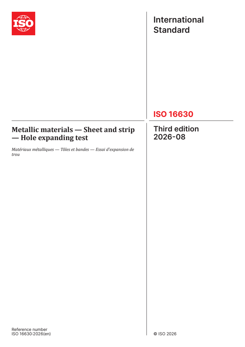
ISO 16630:2026 is an International Standard published by ISO for the hole expanding test on metallic sheets and strips. It specifies how to determine the hole expansion ratio so users can judge whether a product is suitable for forming flanges around punched holes.
What does ISO 16630:2026 specify?
ISO 16630:2026 specifies a test method for measuring the hole expansion ratio in metallic sheets and strips with a thickness from 1.2 mm to 6.0 mm inclusive and a width of at least 90 mm. In practice, it is used on sheet metal to assess formability for flange making around punched holes.
The document is organized into scope, normative references, terms and definitions, symbols and designations, principle, apparatus, test piece, test procedure, calculation of test data, and test report. Annex A is informative and deals with the accuracy of original hole diameters.
What are the key requirements of ISO 16630:2026?
ISO 16630:2026 combines a controlled punching step with a controlled hole expansion step, then calculates the limiting hole expansion ratio from the ruptured hole diameter. The method is designed to make results repeatable, so setup, tool condition, observation and reporting all matter.
Sample preparation and punching
- Clause 7.1 requires three test pieces from the same sample. This gives a small set of repeated results instead of a single value.
- Clause 7.2 sets the geometry of the test piece so the hole is far enough from edges and neighboring holes. That reduces edge effects that could distort the result.
- Clause 7.3 uses a 10 mm punch for the original hole. Clause 7.4 ties the die clearance to thickness, and Table 3 gives example die sizes. In practice, the punching setup must match the sheet thickness.
- Clause 7.5 gives tolerances for the punching tools and notes that wear should be checked. Tool wear can change the hole shape and affect the measured expansion ratio.
- Clause 7.6 requires the punch to stay concentric and perpendicular during punching. That helps keep the hole uniform.
Test apparatus and test conditions
- Clause 6 requires a testing machine that can clamp the piece and stop the expanding tool as soon as a crack appears. The machine also has to control displacement rate.
- Clause 6.2 specifies the tool geometry: a conical expanding tool with a 60° ± 1° tip angle, a clamping die with a suitable inside diameter, and a shoulder radius between 2 mm and 20 mm. The tool hardness must be at least 55 HRC.
- Clause 8.1 gives the test temperature range, and controlled-condition tests are made at (23 ± 5) °C. Clause 8.2 says three tests are normal, with more by agreement.
- Clause 8.4 requires clamping force high enough to prevent draw-in from the clamping area. If draw-in occurs, the result is rejected and the test is repeated.
- Clause 8.5 limits the punch speed to not more than 1 mm/s, and Clause 8.6 requires continuous observation of the hole edge so the test can be slowed when a microcrack appears.
Crack detection, measurement and calculation
- Clause 8.7 says to stop when a through-thickness crack first appears, then measure the ruptured hole diameter in two perpendicular directions. The average of those measurements is used in the calculation.
- Clause 8.7 also allows automated optical crack detection and diameter measurement by agreement, and that choice must be recorded.
- Clause 9 defines the limiting hole expansion ratio, then rounds the average value in line with ISO 80000-1. For buyers and labs, this means the reported result is a rounded percentage based on the expanded hole size, not just the crack occurrence.
- Clause 10 lists what the test report must include, including the standard reference, test piece identification, thickness, average result, number of tests if more than three, optional range, and any agreed variation from the document.
What terms does ISO 16630:2026 define?
- Limiting hole expansion ratio - the ratio of hole expansion in a circular punched hole to the original hole diameter, measured when a crack extends through the thickness.
- Clearance - the gap between the die and punch during hole punching, expressed as a percentage of test piece thickness.
- Through-thickness crack - a crack that has extended through the full thickness of the test piece.
- Microcrack - a crack that has not extended through the full thickness of the test piece.
Who uses ISO 16630:2026?
ISO 16630:2026 is used by metal producers, automotive parts manufacturers, test laboratories, quality managers and buyers who need a formability check for flanging around punched holes. It is especially relevant when a product will be formed after punching and the risk of edge cracking has to be compared between materials or process routes.
What changed in ISO 16630:2026 from the previous edition?
ISO 16630:2026 cancels and replaces ISO 16630:2017. The third edition corrects the definition of the limiting hole expansion ratio, adds visual inspection of the die and punch surfaces, adds observation of the test piece working surface to check for draw-in, changes the crack-detection method and the stopping condition for punch movement, adds an automated optical crack detection and diameter measurement method, and adds Annex A on the accuracy of original hole diameters.
Which standards are used with ISO 16630:2026?
ISO 80000-1 is named as a normative reference. It supports the units and rounding practice used when reporting the limiting hole expansion ratio.
What does the ISO 16630:2026 document contain?
ISO 16630:2026 contains the test principle, apparatus requirements, specimen preparation, test procedure, calculation formulas and reporting items for the hole expanding test. It includes Table 1 for symbols and designations, Table 2 for clearance, Table 3 with example die diameters, Table 4 for punching tool tolerances, and Figures 1 to 3 showing the punching and hole-expanding setup. Formulas are given for clearance and for calculating the limiting hole expansion ratio. Annex A provides an informative example showing how small the variation in original hole diameter can be when the punching conditions are controlled.
Relations
- Effective Date
- 28-Oct-2023
Get Certified
Connect with accredited certification bodies for this standard

Element Materials Technology
Materials testing and product certification.

Inštitut za kovinske materiale in tehnologije
Institute of Metals and Technology. Materials testing, metallurgical analysis, NDT.
Sponsored listings
Frequently Asked Questions
ISO 16630:2026 is a standard published by the International Organization for Standardization (ISO). Its full title is "Metallic materials — Sheet and strip — Hole expanding test". This standard covers: This document describes a method of determining the hole expansion ratio in metallic sheets and strips with a thickness range of 1,2 mm to 6,0 mm inclusive and a width of at least 90 mm. NOTE This test is normally applicable to sheet metal and is used to assess the suitability of the product for forming flanges.
This document describes a method of determining the hole expansion ratio in metallic sheets and strips with a thickness range of 1,2 mm to 6,0 mm inclusive and a width of at least 90 mm. NOTE This test is normally applicable to sheet metal and is used to assess the suitability of the product for forming flanges.
ISO 16630:2026 is classified under the following ICS (International Classification for Standards) categories: 77.040.10 - Mechanical testing of metals. The ICS classification helps identify the subject area and facilitates finding related standards.
ISO 16630:2026 has the following relationships with other standards: It is inter standard links to ISO 16630:2017. Understanding these relationships helps ensure you are using the most current and applicable version of the standard.
ISO 16630:2026 is available in PDF format for immediate download after purchase. The document can be added to your cart and obtained through the secure checkout process. Digital delivery ensures instant access to the complete standard document.
Standards Content (Sample)
International
Standard
ISO 16630
Third edition
Metallic materials — Sheet and strip
2026-08
— Hole expanding test
Matériaux métalliques — Tôles et bandes — Essai d'expansion de
trou
Reference number
© ISO 2026
All rights reserved. Unless otherwise specified, or required in the context of its implementation, no part of this publication may
be reproduced or utilized otherwise in any form or by any means, electronic or mechanical, including photocopying, or posting on
the internet or an intranet, without prior written permission. Permission can be requested from either ISO at the address below
or ISO’s member body in the country of the requester.
ISO copyright office
CP 401 • Ch. de Blandonnet 8
CH-1214 Vernier, Geneva
Phone: +41 22 749 01 11
Email: copyright@iso.org
Website: www.iso.org
Published in Switzerland
ii
Contents Page
Foreword .iv
Introduction .v
1 Scope . 1
2 Normative references . 1
3 Terms and definitions . 1
4 Symbols and designations . 1
5 Principle . 2
6 Apparatus . 3
7 Test piece . 3
8 Test procedure . 5
9 Calculation of test data . 6
10 Test report . 7
Annex A (informative) Accuracy of original hole diameters . 8
iii
Foreword
ISO (the International Organization for Standardization) is a worldwide federation of national standards
bodies (ISO member bodies). The work of preparing International Standards is normally carried out through
ISO technical committees. Each member body interested in a subject for which a technical committee
has been established has the right to be represented on that committee. International organizations,
governmental and non-governmental, in liaison with ISO, also take part in the work. ISO collaborates closely
with the International Electrotechnical Commission (IEC) on all matters of electrotechnical standardization.
The procedures used to develop this document and those intended for its further maintenance are described
in the ISO/IEC Directives, Part 1. In particular, the different approval criteria needed for the different types
of ISO document should be noted. This document was drafted in accordance with the editorial rules of the
ISO/IEC Directives, Part 2 (see www.iso.org/directives).
ISO draws attention to the possibility that the implementation of this document may involve the use of (a)
patent(s). ISO takes no position concerning the evidence, validity or applicability of any claimed patent
rights in respect thereof. As of the date of publication of this document, ISO had not received notice of (a)
patent(s) which may be required to implement this document. However, implementers are cautioned that
this may not represent the latest information, which may be obtained from the patent database available at
www.iso.org/patents. ISO shall not be held responsible for identifying any or all such patent rights.
Any trade name used in this document is information given for the convenience of users and does not
constitute an endorsement.
For an explanation of the voluntary nature of standards, the meaning of ISO specific terms and expressions
related to conformity assessment, as well as information about ISO's adherence to the World Trade
Organization (WTO) principles in the Technical Barriers to Trade (TBT), see www.iso.org/iso/foreword.html.
This document was prepared by Technical Committee ISO/TC 164, Mechanical testing of metals,Subcommittee
SC 2, Ductility testing.
This third edition cancels and replaces the second edition (ISO 16630:2017), which has been technically
revised.
The main changes are as follows:
— correction of the definition of the limiting hole expansion ratio in 3.1;
— addition of the visual inspection on the surfaces of die and punch in the hole expanding test in 6.2.1;
— addition of the observation on the working surface of test piece to make sure no draw-in occurs in 8.4;
— modification of the observation method to detect the first crack in 8.5;
— modification of the condition on stopping the movement of the punch in 8.7;
— addition of the automated method of optical crack detection and measurement of the diameter in 8.7;
— addition of Annex A on the accuracy of original hole diameters.
Any feedback or questions on this document should be directed to the user’s national standards body. A
complete listing of these bodies can be found at www.iso.org/members.html.
iv
Introduction
In automotive parts manufacturing, sheet metal is primarily processed by shearing, bending and stretch-
drawing operations.
Included with these processes are the bending up (plunging) of flanges (rims) around punched holes, and
this can result in rupture of the material.
Various test methods are available to establish the suitability of the sheet metal for the forming processes
involved. The hole expanding test is one of the best methods for evaluating the suitability of the sheet metal
for forming such “flanges” because it closely resembles the process used under production conditions to
form such flanges (plunged rims) starting with punched holes.
Because of the details given in this document, the relevance of the test will be immediately apparent. By
adhering to the procedures laid down in this document, scatter in the test results is minimized.
v
International Standard ISO 16630:2026(en)
Metallic materials — Sheet and strip — Hole expanding test
1 Scope
This document describes a method of determining the hole expansion ratio in metallic sheets and strips
with a thickness range of 1,2 mm to 6,0 mm inclusive and a width of at least 90 mm.
NOTE This test is normally applicable to sheet metal and is used to assess the suitability of the product for
forming flanges.
2 Normative references
The following documents are referred to in the text in such a way that some or all of their content constitutes
requirements of this document. For dated references, only the edition cited applies. For undated references,
the latest edition of the referenced document (including any amendments) applies.
ISO 80000-1, Quantities and units — Part 1: General
3 Terms and definitions
For the purposes of this document, the following terms and definitions apply.
ISO and IEC maintain terminology databases for use in standardization at the following addresses:
— ISO Online browsing platform: available at https:// www .iso .org/ obp
— IEC Electropedia: available at https:// www .electropedia .org/
3.1
limiting hole expansion ratio
ratio of amount of hole expansion obtained in a circular punched hole to the original hole diameter of a
test piece when a conical expanding tool is forced into the hole until any one crack in the hole edge extends
through the test piece thickness
3.2
clearance
gap between the die and the punch, present when punching a hole in a test piece
Note 1 to entry: Clearance is expressed as the ratio of the gap to the test piece thickness.
3.3
through-thickness crack
crack that has extended through the sample thickness
3.4
microcrack
crack that has not extended through the sample thickness
4 Symbols and designations
The symbols used in this document are given in Table 1.
Table 1 — Symbols and designations
Symbol Designation Unit
c clearance %
d inside diameter of the die used for punching a hole in the test piece mm
d
d diameter of the punch used for punching a hole in the test piece mm
p
D inside diameter of the die of the expanding tool mm
d
D average hole diameter after rupture mm
h
D original hole diamete
...