

ISO 19426-2:2026
(Main)Structures for mine shafts — Part 2: Headframe structures
- Abstract
This document specifies the design loads and the design procedures for the structural design of headframe structures of mine shafts and their components for permanent and sinking operations. The headframe includes all structures and their foundations, that are required at the head of all vertical and decline mine shafts for the purposes of supporting and installing winding and sinking ropes, conveyance guides, rope guides and rubbing ropes, equipment for loading and unloading conveyances, safety devices, as well as ancillary sinking and maintenance equipment. The headframe also includes the bank and sub-bank levels. This document does not cover matters of operational safety or layout of the headframe. This document adopts a limit states design philosophy.
- Status
- Published
- Publication Date
- 14-Sep-2026
- Technical Committee
- ISO/TC 82 - Mining
- Drafting Committee
- ISO/TC 82/WG 4 - Structures for mine shafts
- Current Stage
- 6060 - International Standard published
- Start Date
- 15-Sep-2026
- Due Date
- 15-Sep-2026
- Completion Date
- 15-Sep-2026
ISO 19426-2:2026 is an International Standard from ISO for the structural design of headframe structures used at mine shafts. It specifies design loads and design procedures for headframes and their components in permanent and sinking operations, with a limit states design philosophy.
What does ISO 19426-2:2026 specify?
ISO 19426-2:2026 sets out the load cases and design approach for headframe structures at vertical and decline mine shafts. It covers the headframe itself, its foundations, and the bank and sub-bank levels used for winding, sinking, loading, unloading, guidance and related equipment.
The document is organized into scope, normative references, terms and definitions, symbols, materials, nominal loads, and design procedures, followed by an informative annex on load factors and load combinations. Clause 6 is the main technical core because it groups loads by use case: permanent, imposed, installation, operating, and emergency.
| Annex | What it covers |
|---|---|
| Annex A | Load factors and load combinations for operating and emergency conditions |
What are the key requirements of ISO 19426-2:2026?
ISO 19426-2:2026 gives the load basis for design first, then tells designers how to combine those loads and check stability and serviceability. In practice, this means a headframe design has to be built around the specified load cases, not only around the self-weight of the structure.
Materials and design basis
Clause 5 requires structural steel, concrete or structural timber, with the material specified on the structural drawings. Clauses 7.1 and 7.2 tie the design to ISO 2394, ISO 22111, ISO 19338 and ISO 12122-1, so the headframe is not designed in isolation. This matters because the document expects the designer to use the relevant structural design rules for the chosen material and to document the material choice clearly.
Permanent and imposed loads
Clause 6.1 covers permanent loads, including equipment mounted on the headframe and the static contribution of rope guides and rubbing ropes after installation. Clause 6.2 covers imposed loads such as platform loads, bin and chute material loads, conveyance operating loads, headframe-mounted winder loads, kibble loads, bank door operating loads, abnormal loads, earthquake loads and conveyance drop test loads. This is the part that drives the everyday loading scenarios a structure must safely resist.
Installation and operating rope loads
Clause 6.3 addresses loads during rope handling and conveyance installation or replacement, including winding rope installation, doubling-down, tail rope work, rope guide and rubbing rope installation, and conveyance change-over. Clause 6.4 then covers rope operating loads for winding ropes, stage ropes and rope guides or rubbing ropes. For engineers, this means the design must account for both temporary handling conditions and normal service conditions, not just final installed conditions.
Emergency cases
Clause 6.5 sets out emergency rope loads, emergency dropback loads, crash beam and catch plate loads, emergency arrestor anchor loads, headframe-mounted winder emergency loads, energy release loads following rope break, and dogging system loads. These load cases are important because they govern the extreme events the structure may need to withstand without loss of stability.
Stability and serviceability
Clause 7 requires the structure and its parts to resist overturning and uplift under the critical ultimate load combination. It also sets serviceability limits on deflection, including a horizontal deflection limit for the headframe structure and additional tolerance requirements where headframe-mounted winders are involved. In practice, the headframe must be not only strong enough, but also stiff enough to keep the guiding and winding functions working properly.
Load combinations
Annex A gives the partial load factors and combination factors used to build design load combinations for operating and emergency conditions. It also gives a separate approach for combinations that include rope emergency loads. This helps designers turn the individual load cases from Clause 6 into design actions for calculation and checking.
What terms does ISO 19426-2:2026 define?
ISO 19426-2:2026 uses terms from ISO 19426-1 and defines its symbols in Clause 4. A few key symbols are worth understanding:
- Design load (F) - the combined load effect used for structural design checks.
- Emergency load (E) - a load effect representing emergency conditions such as rope break or related faults.
- Rope-operating loads (R) - the loads acting during normal rope operation, including winding and stage rope actions.
- Additional permanent load (Ga) - the permanent load contribution from rope guides and rubbing ropes after installation.
- Conveyance self-weight (Gc) - the weight of the conveyance itself, used in several installation and operating load cases.
- Partial load factors (γ) - factors used to combine loads at ultimate and serviceability limit states.
- Load combination factors (Ψ) - factors used to reduce accompanying variable loads in combinations.
Who uses ISO 19426-2:2026?
ISO 19426-2:2026 is used by mining companies and engineering companies that design headframes for mine shafts. It is also relevant to structural engineers, project teams, equipment suppliers and reviewers who need to define loads, check stability, or assess whether a proposed headframe arrangement fits the required winding, sinking and maintenance functions.
What changed in ISO 19426-2:2026 from the previous edition?
ISO 19426-2:2026 cancels and replaces ISO 19426-2:2018. The foreword states that the main changes are cross-references for bin and chute material loads to ISO 19426-4, earthquake loads to be evaluated using a risk assessment, and additional clarity on emergency rope loads.
Which standards are used with ISO 19426-2:2026?
ISO 19426-2:2026 normatively refers to ISO 2394 for reliability principles, ISO 3010 for seismic actions, ISO 12122-1 for timber characteristic values, ISO 17607-1 for steel execution requirements, ISO 19338 for concrete-structure performance requirements, ISO 19426-1 for vocabulary, ISO 19426-3 for sinking stage loads, ISO 19426-4 for conveyances and dogging system loads, and ISO 22111 for general structural design requirements. Together, these references supply the structural basis, the vocabulary, and the companion load rules needed to apply Part 2 correctly.
What does the ISO 19426-2:2026 document contain?
ISO 19426-2:2026 contains the load categories and formulas used to design headframe structures for mine shafts. Clause 6 gives detailed cases for permanent, imposed, installation, operating and emergency conditions, including load formulas and guidance on impact factors. Clause 7 gives the design checks for reliability, overall stability and serviceability, including deflection limits and rules for headframe-mounted winders. Annex A provides tables and formulas for load factors and load combinations used in design calculations and structural verification.
Relations
- Effective Date
- 16-Sep-2023
Get Certified
Connect with accredited certification bodies for this standard

Bureau Veritas Chile
Bureau Veritas certification services in Chile.
Bureau Veritas Peru
Bureau Veritas certification services in Peru.
BVQI Peru
Bureau Veritas certification in Peru.
Sponsored listings
Frequently Asked Questions
ISO 19426-2:2026 is a standard published by the International Organization for Standardization (ISO). Its full title is "Structures for mine shafts — Part 2: Headframe structures". This standard covers: This document specifies the design loads and the design procedures for the structural design of headframe structures of mine shafts and their components for permanent and sinking operations. The headframe includes all structures and their foundations, that are required at the head of all vertical and decline mine shafts for the purposes of supporting and installing winding and sinking ropes, conveyance guides, rope guides and rubbing ropes, equipment for loading and unloading conveyances, safety devices, as well as ancillary sinking and maintenance equipment. The headframe also includes the bank and sub-bank levels. This document does not cover matters of operational safety or layout of the headframe. This document adopts a limit states design philosophy.
This document specifies the design loads and the design procedures for the structural design of headframe structures of mine shafts and their components for permanent and sinking operations. The headframe includes all structures and their foundations, that are required at the head of all vertical and decline mine shafts for the purposes of supporting and installing winding and sinking ropes, conveyance guides, rope guides and rubbing ropes, equipment for loading and unloading conveyances, safety devices, as well as ancillary sinking and maintenance equipment. The headframe also includes the bank and sub-bank levels. This document does not cover matters of operational safety or layout of the headframe. This document adopts a limit states design philosophy.
ISO 19426-2:2026 is classified under the following ICS (International Classification for Standards) categories: 73.020 - Mining and quarrying. The ICS classification helps identify the subject area and facilitates finding related standards.
ISO 19426-2:2026 has the following relationships with other standards: It is inter standard links to ISO 19426-2:2018. Understanding these relationships helps ensure you are using the most current and applicable version of the standard.
ISO 19426-2:2026 is available in PDF format for immediate download after purchase. The document can be added to your cart and obtained through the secure checkout process. Digital delivery ensures instant access to the complete standard document.
Standards Content (Sample)
International
Standard
ISO 19426-2
Second edition
Structures for mine shafts —
2026-09
Part 2:
Headframe structures
Structures de puits de mine —
Partie 2: Chevalements
Reference number
© ISO 2026
All rights reserved. Unless otherwise specified, or required in the context of its implementation, no part of this publication may
be reproduced or utilized otherwise in any form or by any means, electronic or mechanical, including photocopying, or posting on
the internet or an intranet, without prior written permission. Permission can be requested from either ISO at the address below
or ISO’s member body in the country of the requester.
ISO copyright office
CP 401 • Ch. de Blandonnet 8
CH-1214 Vernier, Geneva
Phone: +41 22 749 01 11
Email: copyright@iso.org
Website: www.iso.org
Published in Switzerland
ii
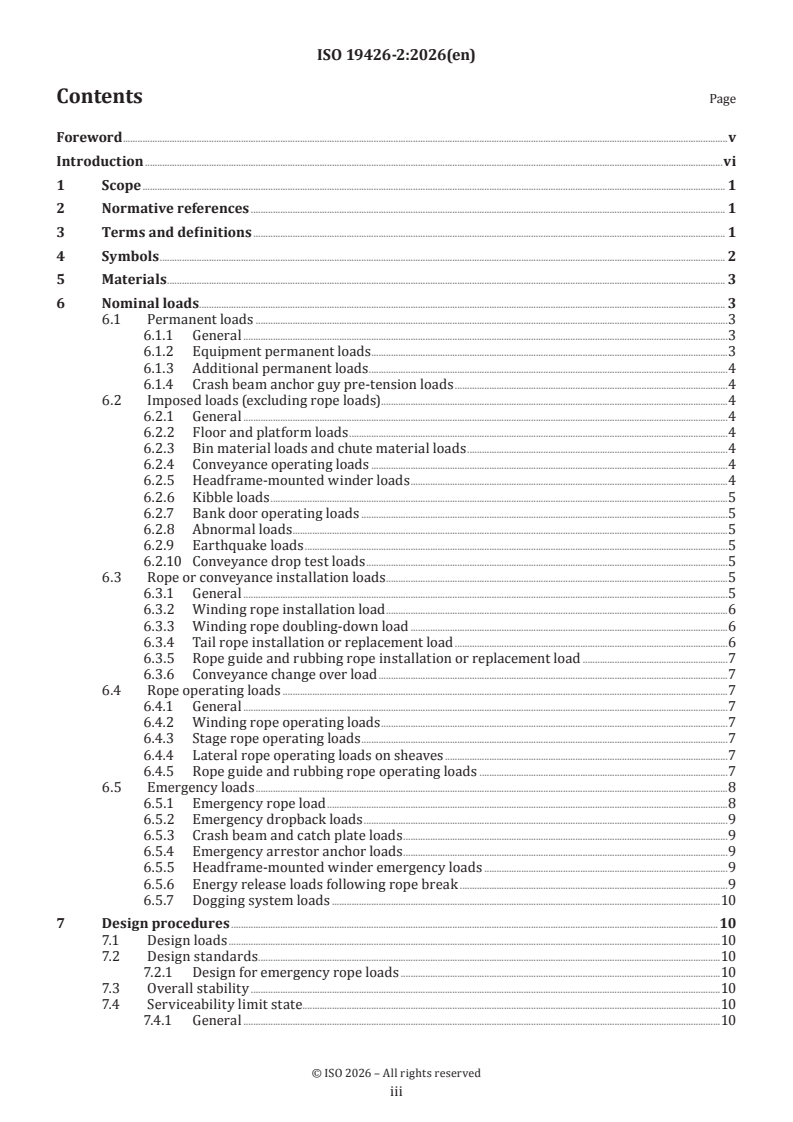
Contents Page
Foreword .v
Introduction .vi
1 Scope . 1
2 Normative references . 1
3 Terms and definitions . 1
4 Symbols . 2
5 Materials . 3
6 Nominal loads . . 3
6.1 Permanent loads .3
6.1.1 General .3
6.1.2 Equipment permanent loads .3
6.1.3 Additional permanent loads .4
6.1.4 Crash beam anchor guy pre-tension loads .4
6.2 Imposed loads (excluding rope loads).4
6.2.1 General .4
6.2.2 Floor and platform loads .4
6.2.3 Bin material loads and chute material loads .4
6.2.4 Conveyance operating loads .4
6.2.5 Headframe-mounted winder loads .4
6.2.6 Kibble loads .5
6.2.7 Bank door operating loads .5
6.2.8 Abnormal loads .5
6.2.9 Earthquake loads .5
6.2.10 Conveyance drop test loads .5
6.3 Rope or conveyance installation loads .5
6.3.1 General .5
6.3.2 Winding rope installation load .6
6.3.3 Winding rope doubling-down load .6
6.3.4 Tail rope installation or replacement load .6
6.3.5 Rope guide and rubbing rope installation or replacement load .7
6.3.6 Conveyance change over load .7
6.4 Rope operating loads .7
6.4.1 General .7
6.4.2 Winding rope operating loads .7
6.4.3 Stage rope operating loads .7
6.4.4 Lateral rope operating loads on sheaves .7
6.4.5 Rope guide and rubbing rope operating loads .7
6.5 Emergency loads .8
6.5.1 Emergency rope load .8
6.5.2 Emergency dropback loads .9
6.5.3 Crash beam and catch plate loads .9
6.5.4 Emergency arrestor anchor loads .9
6.5.5 Headframe-mounted winder emergency loads .9
6.5.6 Energy release loads following rope break .9
6.5.7 Dogging system loads .10
7 Design procedures .10
7.1 Design loads .10
7.2 Design standards .10
7.2.1 Design for emergency rope loads .10
7.3 Overall stability .10
7.4 Serviceability limit state.10
7.4.1 General .10
iii
7.4.2 Deflection limits .10
7.4.3 Headframe-mounted winders .10
Annex A (informative) Load factors and load combinations .11
Bibliography .13
iv
Foreword
ISO (the International Organization for Standardization) is a worldwide federation of national standards
bodies (ISO member bodies). The work of preparing International Standards is normally carried out through
ISO technical committees. Each member body interested in a subject for which a technical committee
has been established has the right to be represented on that committee. International organizations,
governmental and non-governmental, in liaison with ISO, also take part in the work. ISO collaborates closely
with the International Electrotechnical Commission (IEC) on all matters of electrotechnical standardization.
The procedures used to develop this document and those intended for its further maintenance are described
in the ISO/IEC Directives, Part 1. In particular, the different approval criteria needed for the different types
of ISO document should be noted. This document was drafted in accordance with the editorial rules of the
ISO/IEC Directives, Part 2 (see www.iso.org/directives).
ISO draws attention to the possibility that the implementation of this document may involve the use of (a)
patent(s). ISO takes no position concerning the evidence, validity or applicability of any claimed patent
rights in respect thereof. As of the date of publication of this document, ISO had not received notice of (a)
patent(s) which may be required to implement this document. However, implementers are cautioned that
this may not represent the latest information, which may be obtained from the patent database available at
www.iso.org/patents. ISO shall not be held responsible for identifying any or all such patent rights.
Any trade name used in this document is information given for the convenience of users and does not
constitute an endorsement.
For an explanation of the voluntary nature of standards, the meaning of ISO specific terms and expressions
related to conformity assessment, as well as information about ISO's adherence to the World Trade
Organization (WTO) principles in the Technical Barriers to Trade (TBT), see www.iso.org/iso/foreword.html.
This document was prepared by Technical Committee ISO/TC 82, Mining.
This second edition cancels and replaces the first edition (ISO 19426-2:2018), which has been technically
revised.
The main changes are as follows:
— bin and chute material loads cross-referenced to ISO 19426-4;
— earthquake loads to be evaluated using a risk assessment;
— additional clarity on the emergency rope loads.
A list of all parts in the ISO 19426 series can be found on the ISO website.
Any feedback or questions on this document should be directed to the user’s national standards body. A
complete listing of these bodies can be found at www.iso.org/members.html.
v
Introduction
Many mining companies, and many of the engineering companies which provide designs for mines, operate
globally so ISO 19426 series was developed in response to a desire for a unified global approach to the safe
and robust design of structures for mine shafts. The characteristics of ore bodies, such as their depth and
shape, vary in different areas so different design approaches have been developed and proven with use over
time in different countries. Bringing these approaches together in ISO 19426 series will facilitate improved
safety and operational reliability.
The majority of the material in ISO 19426 series deals with the loads to be applied in the design of structures
for mine shafts. Some principles for structural design are given, but for the most part it is assumed that local
standards will be used for the structural design.
vi
International Standard ISO 19426-2:2026(en)
Structures for mine shafts —
Part 2:
Headframe structures
1 Scope
This document specifies the design loads and the design procedures for the structural design of headframe
structures of mine shafts and their components for permanent and sinking operations. The headframe
includes all structures and their foundations, that are required at the head of all vertical and decline mine
shafts for the purposes of supporting and installing winding and sinking ropes, conveyance guides, rope
guides and rubbing ropes, equipment for loading and unloading conveyances, safety devices, as well as
ancillary sinking and maintenance equipment. The headframe also includes the bank and sub-bank levels.
This document does not cover matters of operational safety or layout of the headframe.
This document adopts a limit states design philosophy.
2 Normative references
The following documents are referred to in the text in such a way that some or all of their content constitutes
requirements of this document. For dated references, only the edition cited applies. For undated references,
the latest edition of the referenced document (including any amendments) applies.
ISO 2394, General principles on reliability for structures
ISO 3010, Bases for design of structures — Seismic actions on structures
ISO 12122-1, Timber structures — Determination of characteristic values — Part 1: Basic requirements
ISO 17607-1, Steel structures — Execution of structural steelwork — Part 1: General requirements and terms
and definitions
ISO 19338, Performance requirements for standards on concrete structures
ISO 19426-1, Structures for mine shafts — Part 1: Vocabulary
ISO 19426-3, Structures for mine shafts — Part 3: Sinking stage
ISO 19426-4, Structures for mine shafts — Part 4: Conveyances
ISO 22111, Bases for design of structures — General requirements
3 Terms and definitions
For the purposes of this document, the terms and definitions given in ISO 19426-1 apply.
ISO and IEC maintain terminology databases for use in standardization at the following addresses:
— ISO Online browsing platform: available at https:// www .iso .org/ obp
— IEC Electropedia: available at http:// www .electropedia .org
4 Symbols
D rope or conveyance installation load (N)
D winding rope doubling-down load (N)
dd
D rope guide or rubbing rope installation load (N)
g
D winding rope installation load (N)
h
D tail rope installation or replacement load (N)
t
D conveyance change-over load (N)
v
E emergency load (N)
E rope emergency load (N)
r
E and E tensions in the ropes on each side of the winder drum (N)
r1 r2
E energy release load following rope break (N)
re
E short circuit torque (Nm)
st
E winder brake failure load (Nm)
wb
e base for natural logarithms (mathematical constant)
F design load or load effect (N, Nm)
F pre-tension load of the crash-beam-anchor guy (N)
ag
F kibble load applied to the bank doors (N)
k
g gravity acceleration constant (m/s )
G permanent load or load effect (N, Nm)
G additional permanent load or load effect from rope guides and rubbing ropes (N)
a
G conveyance self-weight (N)
c
G weight of the relevant length of winding rope, rope guide or rubbing rope (N)
r
G weight of the relevant length of tail rope, rope guide or rubbing rope (N)
t
L full length of the rope guide or rubbing rope (m)
m unit mass of the rope guide or rubbing rope (kg/m)
r
n number of winding ropes
P payload used during doubling-down (N)
Q imposed load or load effect (excluding rope load) (N, Nm)
Q dominant imposed load or load effect under consideration (N, Nm)
Q to Q additional independent imposed loads or load effects (N, Nm)
3 n
R varying rope guide or rubbing rope horizontal load under operating conditions (N)
h
R varying rope guide or rubbing rope vertical load under operating conditions (N)
v
R to R rope operating loads (N)
1 n
minimum tension in a rope guide or rubbing rope, or the weight of the suspended tensioning
T
r
block (N)
T short circuit torque (Nm)
st
W weight of kibble and payload (N)
K
α rope or conveyance impact factor
c
α horizontal impact factor
ch
α temperature factor
cv
α short circuit torque impact factor
st
α vertical impact factor
v
μ coefficient of friction between winding rope and winder drum
γ partial load factor for all loads when combined with the rope emergency load (= 1,05)
e
γ partial load factor for permanent load
γ partial load factor for rope-operating load
f1
γ partial loa
...