


ISO/TR 17534-3:2015
(Main)Acoustics — Software for the calculation of sound outdoors — Part 3: Recommendations for quality assured implementation of ISO 9613-2 in software according to ISO 17534-1
Acoustics — Software for the calculation of sound outdoors — Part 3: Recommendations for quality assured implementation of ISO 9613-2 in software according to ISO 17534-1
ISO/TR 17534-3:2015 contains additional recommendations for the calculation method of ISO 9613‑2 that are agreed on to be implemented in software quality ensured test cases with detailed results that allow checking the correct implementation and forms to declare conformity with these requirements by a specified software product.
Acoustique — Logiciels de prévision de bruit dans l'environnement — Partie 3: Recommandations pour l'assurance qualité mise en oeuvre de la norme ISO 9613-2 dans le logiciel selon ISO 17534-1
General Information
- Status
- Published
- Publication Date
- 12-Jan-2015
- Technical Committee
- ISO/TC 43/SC 1 - Noise
- Drafting Committee
- ISO/TC 43/SC 1 - Noise
- Current Stage
- 9092 - International Standard to be revised
- Start Date
- 30-Oct-2024
- Completion Date
- 14-Feb-2026
Overview
ISO/TR 17534-3:2015 is a technical report from ISO that provides recommendations for a quality‑assured implementation of the outdoor sound propagation calculation method given in ISO 9613‑2. Intended as a method‑specific addendum to ISO 17534‑1 (software quality requirements and QA), this report supplies agreed implementation rules, a suite of test cases with detailed step‑by‑step results, and the forms needed for a software Declaration of Conformity (DoC). It helps ensure that acoustic modelling software correctly and consistently implements the ISO 9613‑2 engineering method for outdoor noise prediction.
Key topics and technical requirements
- Scope and normative references: Identifies ISO 9613‑2 and ISO 17534‑1 as essential references and clarifies terms and definitions used.
- Agreed additional recommendations: Minimum, transparent rules to reduce modelling ambiguity when replacing complex wave behaviour by ray paths (screening, diffraction, path selection).
- Specific algorithmic clarifications:
- Screening and ray‑path identification rules
- Calculation of path‑length difference (z) and related geometry handling
- Treatment of diffraction (including barriers on reflecting ground and lateral diffraction limits)
- Limitations on maximal possible barrier attenuation
- Handling of ground effects, elevated ground, and multi‑reflection (higher‑order reflections)
- Comprehensive test suite: A set of test cases (T01–T19 in the report) covering flat and varying ground, reflecting/porous ground, barriers (short/long), buildings of various shapes and receiver heights, and step‑by‑step and final result intervals to verify software results.
- Declaration of Conformity (DoC): Forms and guidance for software vendors to declare conformity of their product implementation with the recommendations.
Practical applications and users
- Acoustic software developers - implement and validate ISO 9613‑2 functionality in modelling tools and ensure traceable QA.
- Acoustic consultants and engineers - rely on validated software for environmental noise assessment, planning, and impact studies.
- Regulators and certification bodies - evaluate and accept software products based on the provided test cases and DoC forms.
- Quality assurance teams - establish automated test workflows using the detailed test suite to detect implementation errors or regressions.
Related standards
- ISO 9613‑2:1996 - Attenuation of sound during propagation outdoors (calculation method).
- ISO 17534‑1 - Acoustics - Software for the calculation of sound outdoors - Part 1: Quality requirements and quality assurance.
- ISO/TR 17534‑2 - General recommendations for test cases and QA interface.
Keywords: ISO TR 17534-3:2015, ISO 9613-2, acoustics, outdoor sound calculation, noise prediction software, software quality assurance, test cases, declaration of conformity.

Get Certified
Connect with accredited certification bodies for this standard

BSMI (Bureau of Standards, Metrology and Inspection)
Taiwan's standards and inspection authority.
Sponsored listings
Frequently Asked Questions
ISO/TR 17534-3:2015 is a technical report published by the International Organization for Standardization (ISO). Its full title is "Acoustics — Software for the calculation of sound outdoors — Part 3: Recommendations for quality assured implementation of ISO 9613-2 in software according to ISO 17534-1". This standard covers: ISO/TR 17534-3:2015 contains additional recommendations for the calculation method of ISO 9613‑2 that are agreed on to be implemented in software quality ensured test cases with detailed results that allow checking the correct implementation and forms to declare conformity with these requirements by a specified software product.
ISO/TR 17534-3:2015 contains additional recommendations for the calculation method of ISO 9613‑2 that are agreed on to be implemented in software quality ensured test cases with detailed results that allow checking the correct implementation and forms to declare conformity with these requirements by a specified software product.
ISO/TR 17534-3:2015 is classified under the following ICS (International Classification for Standards) categories: 17.140.01 - Acoustic measurements and noise abatement in general. The ICS classification helps identify the subject area and facilitates finding related standards.
ISO/TR 17534-3:2015 is available in PDF format for immediate download after purchase. The document can be added to your cart and obtained through the secure checkout process. Digital delivery ensures instant access to the complete standard document.
Standards Content (Sample)
TECHNICAL ISO/TR
REPORT 17534-3
First edition
2015-01-15
Acoustics — Software for the
calculation of sound outdoors —
Part 3:
Recommendations for quality assured
implementation of ISO 9613-2 in
software according to ISO 17534-1
Acoustique — Logiciels de prévision de bruit dans l’environnement —
PartieParte 3: Recommandations pour l’assurance qualité mise en
oeuvre de la norme ISO 9613-2 dans le logiciel selon ISO 17534-1
Reference number
©
ISO 2015
© ISO 2015
All rights reserved. Unless otherwise specified, no part of this publication may be reproduced or utilized otherwise in any form
or by any means, electronic or mechanical, including photocopying, or posting on the internet or an intranet, without prior
written permission. Permission can be requested from either ISO at the address below or ISO’s member body in the country of
the requester.
ISO copyright office
Case postale 56 • CH-1211 Geneva 20
Tel. + 41 22 749 01 11
Fax + 41 22 749 09 47
E-mail copyright@iso.org
Web www.iso.org
Published in Switzerland
ii © ISO 2015 – All rights reserved
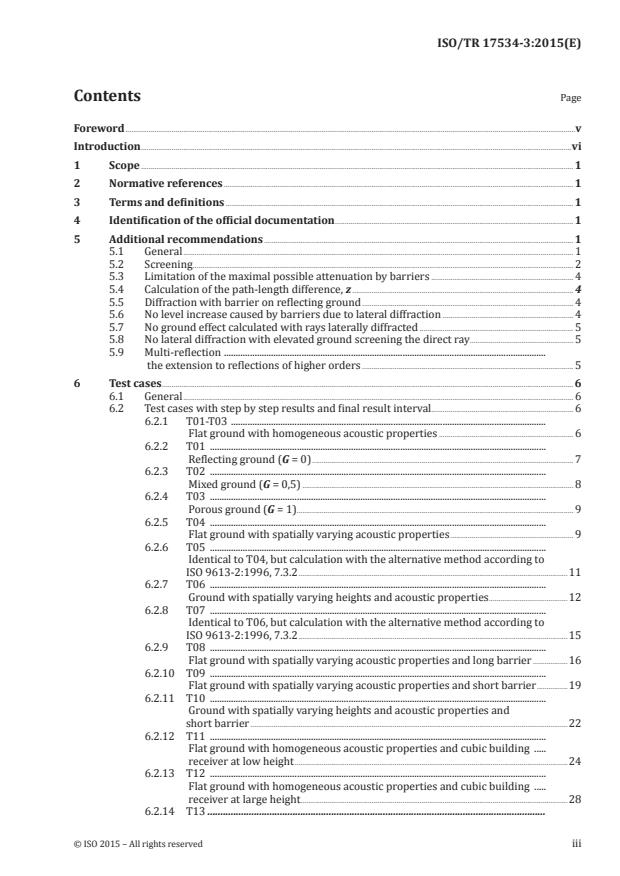
Contents Page
Foreword .v
Introduction .vi
1 Scope . 1
2 Normative references . 1
3 Terms and definitions . 1
4 Identification of the official documentation . 1
5 Additional recommendations . 1
5.1 General . 1
5.2 Screening . 2
5.3 Limitation of the maximal possible attenuation by barriers . 4
5.4 Calculation of the path-length difference, z . 4
5.5 Diffraction with barrier on reflecting ground . 4
5.6 No level increase caused by barriers due to lateral diffraction . 4
5.7 No ground effect calculated with rays laterally diffracted . 5
5.8 No lateral diffraction with elevated ground screening the direct ray. 5
5.9 Multi-reflection .
the extension to reflections of higher orders . 5
6 Test cases . 6
6.1 General . 6
6.2 Test cases with step by step results and final result interval. 6
6.2.1 T01-T03 .
Flat ground with homogeneous acoustic properties . 6
6.2.2 T01 .
Reflecting ground (G = 0) . 7
6.2.3 T02 .
Mixed ground (G = 0,5) . 8
6.2.4 T03 .
Porous ground (G = 1). 9
6.2.5 T04 .
Flat ground with spatially varying acoustic properties . 9
6.2.6 T05 .
Identical to T04, but calculation with the alternative method according to
ISO 9613-2:1996, 7.3.2 .11
6.2.7 T06 .
Ground with spatially varying heights and acoustic properties .12
6.2.8 T07 .
Identical to T06, but calculation with the alternative method according to
ISO 9613-2:1996, 7.3.2 .15
6.2.9 T08 .
Flat ground with spatially varying acoustic properties and long barrier .16
6.2.10 T09 .
Flat ground with spatially varying acoustic properties and short barrier .19
6.2.11 T10 .
Ground with spatially varying heights and acoustic properties and
short barrier .22
6.2.12 T11 .
Flat ground with homogeneous acoustic properties and cubic building .
receiver at low height .24
6.2.13 T12 .
Flat ground with homogeneous acoustic properties and cubic building .
receiver at large height.28
6.2.14 T13 .
Flat ground with homogeneous acoustic properties and polygonal
building .
receiver at low height .31
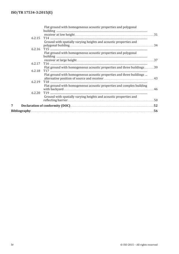
6.2.15 T14 .
Ground with spatially varying heights and acoustic properties and
polygonal building .34
6.2.16 T15 .
Flat ground with homogeneous acoustic properties and polygonal
building .
receiver at large height.37
6.2.17 T16 .
Flat ground with homogeneous acoustic properties and three buildings .39
6.2.18 T17 .
Flat ground with homogeneous acoustic properties and three buildings .
alternative position of source and receiver .43
6.2.19 T18 .
Flat ground with homogeneous acoustic properties and complex building
with backyard .46
6.2.20 T19 .
Ground with spatially varying heights and acoustic properties and
reflecting barrier . . .50
7 Declaration of conformity (DOC) .52
Bibliography .56
iv © ISO 2015 – All rights reserved
Foreword
ISO (the International Organization for Standardization) is a worldwide federation of national standards
bodies (ISO member bodies). The work of preparing International Standards is normally carried out
through ISO technical committees. Each member body interested in a subject for which a technical
committee has been established has the right to be represented on that committee. International
organizations, governmental and non-governmental, in liaison with ISO, also take part in the work.
ISO collaborates closely with the International Electrotechnical Commission (IEC) on all matters of
electrotechnical standardization.
The procedures used to develop this document and those intended for its further maintenance are
described in the ISO/IEC Directives, Part 1. In particular the different approval criteria needed for the
different types of ISO documents should be noted. This document was drafted in accordance with the
editorial rules of the ISO/IEC Directives, Part 2 (see www.iso.org/directives).
Attention is drawn to the possibility that some of the elements of this document may be the subject of
patent rights. ISO shall not be held responsible for identifying any or all such patent rights. Details of
any patent rights identified during the development of the document will be in the Introduction and/or
on the ISO list of patent declarations received (see www.iso.org/patents).
Any trade name used in this document is information given for the convenience of users and does not
constitute an endorsement.
For an explanation on the meaning of ISO specific terms and expressions related to conformity
assessment, as well as information about ISO’s adherence to the WTO principles in the Technical Barriers
to Trade (TBT) see the following URL: Foreword - Supplementary information
The committee responsible for this document is ISO/TC 43, Acoustics, Subcommittee SC 1, Noise.
ISO 17534 consists of the following parts, under the general title Acoustics — Software for the calculation
of sound outdoors:
— Part 1: Quality requirements and quality assurance
— Part 2: General recommendations for test cases and quality assurance interface [Technical report]
— Part 3: Recommendations for quality ensured implementation of ISO 9613-2 in software according to
ISO 17534-1 [Technical report]
Introduction
The general structure of the ISO 17534 series and the various Technical Reports are shown in Figure 1.
The International Standard itself describes the measures necessary to ensure a high quality of calculation
methods implemented in different software products with respect to correctness and precision. The
requirements and specifications included are obviously independent from a specific calculation method,
because they should be applied for all of them.
This Technical Report contains additional recommendations, test cases of both types according to
ISO 17534-1:—, A.2 and A.3, and the forms to declare conformity by software manufacturers related
to the quality ensured implementation of the calculation method ISO 9613-2. The test cases are based
on the set of test cases and input parameters documented in Reference [1]. This Technical Report is
a first step. Contents will be supplemented step by step and or even withdrawn if a standardization
committee responsible for this specific calculation method decides about an alternative formulation
that is in agreement with the requirements of ISO 17534.
ISO 17534 series
ISO 17534-1
ISO/TR 17534-3 ISO/TR 17534-X
ISO/TR 17534-2
Recommendations for quality
Recommendations for quality
General recommendations
. . .
assured implementation
assured implementation
for test cases and
of ISO 9613-2 in software of XXX in software
quality assurance interface
according to ISO 17534-1
according to ISO 17534-1
1) Identi ication of the of icial documentation
2) Additional recommendations
3) Test suite (set of test cases with results)
4) Forms to declare conformity
5) Method - speci ic addendum to QA
Figure 1 — Structure of ISO 17534 series consisting of the main Part 1 and subordinated
Technical Reports
vi © ISO 2015 – All rights reserved
TECHNICAL REPORT ISO/TR 17534-3:2015(E)
Acoustics — Software for the calculation of sound outdoors —
Part 3:
Recommendations for quality assured implementation of
ISO 9613-2 in software according to ISO 17534-1
1 Scope
This Technical Report contains additional recommendations for the calculation method of ISO 9613-2
that are agreed on to be implemented in software quality ensured test cases with detailed results that
allow checking the correct implementation and forms to declare conformity with these requirements
by a specified software product.
2 Normative references
The following documents, in whole or in part, are normatively referenced in this document and are
indispensable for its application. For dated references, only the edition cited applies. For undated
references, the latest edition of the referenced document (including any amendments) applies.
ISO 9613-2:1996, Acoustics — Attenuation of sound during propagation outdoors — Part 2: General method
of calculation
ISO 17534-1:—, Acoustics — Software for the calculation of sound outdoors — Part 1: Quality requirements
and quality assurance
ISO/TR 17534-2, Acoustics — Software for the calculation of sound outdoors — Part 2: General
recommendations for test cases and quality assurance interface
3 Terms and definitions
For the purposes of this document, the terms and definitions given in ISO 9613-2, ISO 17534-1, and
ISO/TR 17534-2 apply.
4 Identification of the official documentation
ISO 9613-2:1996, Acoustics — Attenuation of sound during propagation outdoors — Part 2: General method
of calculation.
NOTE ISO 9613-2 describes a method for calculating the attenuation of sound during propagation outdoors in
order to predict the levels of environmental noise at a distance from a variety of sources. The method predicts the
equivalent continuous A-weighted sound pressure level (as described in ISO 1996) under meteorological conditions.
5 Additional recommendations
5.1 General
The calculation of sound propagation with the engineering method specified in ISO 9613-2 is an
approximation where the sound wave propagating over a structured terrain with any complexity is
replaced by some few ray paths. In many cases, there are more alternatives to define these paths and for
each of these alternatives examples can be constructed where the method fails. It is important to keep
the method as transparent as possible to be able to avoid the resulting traps in modelling. Therefore, the
additional rules defined herein are kept to a minimum, to ensure a common interpretation of ISO 9613-2
to reduce uncertainty in the calculations. These rules are based on experience with various software
implementations, and have been agreed upon to maintain consistency in results.
The obviousness of additional recommendations is explained in the following by introductory notes in
5.2 up to 5.9. Furthermore, each of these additional recommendations is classified.
— A: Agreed solution for a problem incompletely or even not addressed in ISO 9613-2:1996
— B: Better and consistent solution for a problem inconsistently or unsatisfactorily treated in
ISO 9613-2:1996
— C: Common interpretation of an unclear content of ISO 9613-2:1996.
5.2 Screening
NOTE The calculation of screening (A ), as described in ISO 9613-2, takes into account diffraction over the
bar
top edge(s) and lateral diffraction around the vertical edge(s). The calculation is based on the difference of the
path length of the ray over or around the barrier edges and the shortest distance source–receiver neglecting the
blocking objects (direct ray).
The ray over the upper edge can be constructed as the shortest possible polygon line source – edge – receiver in
a vertical plane containing source and receiver similar to a rubber band connecting these two points. In the same
way, the rays around the two vertical edges can be constructed as the shortest polygon lines around these edges
in a further plane perpendicular to the vertical plane and also containing source and receiver positions.
This construction of the relevant ray paths in two perpendicular planes is equivalent to Formula (16) in ISO 9613-2,
in the case of a right angle between the line source – receiver and the screen.
However, according to ISO 9613-2:1996, the calculation of the path-length difference z over the upper edge(s)
shall generally and with any orientation of the line source – receiver relative to the screen be performed with
ISO 9613-2:1996, Formula (16) for single diffraction and ISO 9613-2:1996, Formula (17) for double diffraction,
where a component distance “a” parallel to the barrier edge between source and receiver is one of the input
parameters. But with double diffraction, the method fails and is even not applicable in general cases where the
two diffracting edges are not parallel, because a single component distance parallel to the barrier edge between
source and receiver cannot be defined. For more diffracting edges, the two most effective barriers are taken to
reduce the problem to the case of double diffraction; therefore, the general case of more than two diffractions is
also not applicable.
However, the described rubber band construction of the relevant ray paths in two planes identical with the
method of ISO 9613-2, in case of a single diffraction and with a right angle between the line source - receiver and
the screen, can consistently be extended to the most general case of any number and orientation of diffracting
edges. This is the recommended alternative method to overcome the described problem as long as it is not solved
generally in a revised version of ISO 9613-2.
Lateral diffraction for more than one screening object blocking the direct ray source – receiver is
not explicitly mentioned in ISO 9613-2. The recommended method to solve this frequently occurring
problem is a consistent extension of the lateral diffraction with one barrier as long as it is not solved
generally in a revised version of ISO 9613-2.
If acoustically impervious objects like barriers or buildings are blocking the direct straight line from
source to receiver, three contributing ray paths should be taken into account in the most general case;
one over top and two laterally diffracted around the objects. The ray over top is constructed in a vertical
plane EV, the lateral diffracted rays in a plane EL. Both planes contain source and receiver, plane EV is
perpendicular to the reference plane x-y and plane EL is perpendicular to plane EV.
The ray path in plane EV connects source and receiver like a ribbon enveloping the diffracting edges as
shown in Figure 2.
It is obvious that in plane EL, the two ray paths transmitting most sound energy to the receiver should
be taken into account. In many cases, these are the shortest possible ray paths left and right from the
direct path S-R. Figure 3 shows such a clear example without ambiguity. However, it should be mentioned
2 © ISO 2015 – All rights reserved
that there are more complex cases where the shortest paths form a zig-zag-line or even where not the
shortest paths are the most important ones. A common strategy will be developed and included in
further revisions.
Lateral diffraction paths are neglected if the maximal distance of one or more diffracting edges
contributing to the ribbon from the straight line source – receiver exceeds this maximal distance in the
plane EV by a factor more than 8.
The path length difference, z, of each of these relevant contributions is the difference in length of the
ribbon and the straight direct line from source to receiver. The length of the polygon-segments between
the first and the last diffracting edge is the parameter e needed in ISO 9613-2:1996, Formula (15).
e2
e3
e1
dsr
dss
+
Key
dss polygon-segment from source to the first active diffraction edge
dsr polygon-segment from the last active diffraction edge to the receiver
e1…en polygon-segment between two following active diffraction edges
Figure 2 — The calculation ray in plane EV
R
+ S
Key
R receiver
S source
Figure 3 — The two calculation rays in plane EL
Classification of this additional recommendation: A, B.
5.3 Limitation of the maximal possible attenuation by barriers
According to ISO 9613-2:1996 “the barrier attenuation D , in any octave band, should not be taken
z
to be greater than 20 dB in the case of single diffraction and 25 dB in the case of double diffraction”.
The reason for this limitation is that the level behind screens and other objects can be determined by
other ray paths caused for instance by reflections. However, it was obviously overseen that D is not
z
only calculated for the diffraction over the upper edge, but also for the lateral diffraction around the
vertical edges. A limitation of all three contributions will result in an effective limitation of the barrier
attenuation of 15 dB with a single screen. On the other side, the contribution of a lateral diffraction
should vanish if an object like a barrier is long and the vertical edges are far away from the receiver.
Therefore, it should be the recommended interpretation of ISO 9613-2 to apply this limitation of D only
z
for the diffraction over the top edge.
The restriction of D , not to be taken greater than 20 dB in the case of single diffraction and 25 dB in the
z
case of double diffraction in any octave band, should only be applied for diffraction over the upper edges.
Classification of this additional recommendation: C.
5.4 Calculation of the path-length difference, z
NOTE D is calculated in ISO 9613-2:1996, Formula (14) as 10 times the logarithm of an expression that depends
z
on the path-length difference z, where z is given a negative sign if the ray source – receiver passes above the top
edge. Therefore, increasing the height of source and/or receiver will result in a reduced barrier attenuation and
with a certain height of the ray above the top edge this barrier, attenuation will be 0. Increasing the height more
will result in an argument of the logarithm that falls even below 1; the resulting D will be negative producing an
z
apparent increase of the level behind a barrier over the value without the barrier. As this was obviously overseen
when this equation was designed and due to the very simple improvement solving this problem, the calculation of
D according to ISO 9613-2:1996, Formula (14) is recommended in two steps.
z
Formula (14) of ISO 9613-2:1996 should be applied stepwise.
−2λ
a) z =
min
CC K
()
23 met
for zz>
C
min
10 lg 3+ CzK
met
b) D = dB
λ
z
for zz≤
minn
Classification of this additional recommendation: B.
5.5 Diffraction with barrier on reflecting ground
The diffraction over the top edge is calculated with ISO 9613-2:1996, Formula (12) with A = D – A > 0.
bar z gr
The method should take into account that the height of the effective ray path will be increased by the
barrier and therefore the influence of the ground will be reduced. But with reflecting ground A is
gr
negative (−3 dB) and therefore the installation of a barrier with even very low height will remove the
ground effect and dupe a barrier attenuation of 3 dB.
Formula (12) of ISO 9613-2:1996 should not be applied with A < 0.
gr
Classification of this additional recommendation: B.
5.6 No level increase caused by barriers due to lateral diffraction
NOTE In software realizations, the combination of ground simulated by contour lines or grids of height points
with objects can, in rare cases, cause a level increase behind elevated ground if a screening object is inserted due
to lateral diffraction. This can easily be avoided by a simple strategy.
4 © ISO 2015 – All rights reserved
If the direct ray is screened, the three barrier attenuations A , A , and A and an
bar,top bar,side1 bar,side2
effective value
-0,1 AAbar,top -0,1 -0,1 A
bar,side1bar,side22
A =-10lg(10 +10 +10 )dB
bar
should be calculated. If the result of this equation is negative, the effective A is 0.
bar
Classification of this additional recommendation: B.
5.7 No ground effect calculated with rays laterally diffracted
NOTE In ISO 9613-2, the determination of the ground effect A and of the barrier attenuation A are
gr bar
independent parts carried out consecutively. The lateral diffraction is not equivalent to the calculation of
additional contributions with their own ground influence, but produces a modification of the barrier attenuation
between source and receiver. This is not unambiguously expressed in ISO 9613-2 and can, therefore, in some
cases, cause different interpretations. This can be avoided by a simple clarification.
The ground effect A in ISO 9613-2:1996, 7.3 is determined for each pair of source-receiver from the
gr
path in the vertical plane EV; the paths of lateral diffracted sound in plane EL are not considered.
Classification of this additional recommendation: C.
5.8 No lateral diffraction with elevated ground screening the direct ray
The screening by elevated ground is not explicitly mentioned in ISO 9613-2 but can be solved by treating
a contour line or a triangulation line forming the ground surface like the top edge of a barrier. However,
lateral diffraction around hills or other elevated parts of the ground is not covered by the method
described for barriers. Taking into account that the profile of such formations is generally not bounded
by vertical edges, lateral diffraction should not be taken into account in such cases. This should be
clarified unambiguously to avoid different interpretations.
If at least one contour line of the ground is relevant for the screening and influences the shape of the
rubber band from source to receiver, lateral diffraction is not calculated.
Classification of this additional recommendation: C.
5.9 Multi-reflection – the extension to reflections of higher orders
ISO 9613-2 describes the calculation of specular reflections based on the method of mirror image
sources. The application of the method to calculate the contribution of even higher order reflections is
not explicitly mentioned, but a trivial extension by repeating the procedure with these mirror images.
Taking into account the broad application of ISO 9613-2 with industrial noise and in other fields of noise
prediction, this extension should be integrated explicitly.
th
The n order image source Scn is the image of the image source Scn-1. The construction of the real ray
path of a second order reflection is shown in Figure 4.
Figure 4 — Example to explain the construction of a 2nd order reflection
with image sources Sc1 and Sc2
Classification of this additional recommendation: A.
6 Test cases
6.1 General
The test cases are complete in the sense that all data necessary to perform the calculation are given.
For the precisely defined test cases, the step-by-step results are shown with precision 2 according to
ISO 17534-1:—, A.2.
Test cases T01 up to T07 can be solved by applying ISO 9613-2 exclusively. Test cases T08 up to T19 are
based on ISO 9613-2 and the application of additional recommendations according to 5.2 up to 5.9.
6.2 Test cases with step by step results and final result interval
6.2.1 T01-T03 – Flat ground with homogeneous acoustic properties
Key
S source
R receiver
Figure 5 — Test case to check free sound propagation with different conditions
Input data:
Table 1 — Coordinates of source, S, and receiver, R
x y z
in m in m in m
S 10 10 1
R 200 50 4
6 © ISO 2015 – All rights reserved
Table 2 — Octave-band sound power levels (linear) of the source
Quantity Unit Values
f Hz 63 125 250 500 1 000 2 000 4 000 8 000
L dB 93 93 93 93 93 93 93 93
W
The band levels and the A-weighted sound pressure level at the receiver should be calculated for T = 20°C
and F = 70 %.
6.2.2 T01 – Reflecting ground (G = 0)
Step by step results:
0 d
p
sm r
Key
s source region
m middle region
r receiver region
d 2-dimensional distance
p
Figure 6 — Regions according to Figure 1 in ISO 9613-2
Table 3 — Single number step by step results
Quantity Unit Values
d (2-dimensional distance) m 194,16
p
d (3-dimensional distance) m 194,19
A dB 56,76
div
length of s-region m 30,00
length of r-region m 120,00
length of m-region m 44,16
q (ISO 9613-2:1996, Table 3 footnote 2) 0,23
Table 4 — Spectral step by step results
Quantity Unit Values
f Hz 63 125 250 500 1 000 2 000 4 000 8 000
L dB 93 93 93 93 93 93 93 93
W
α-atm(20°,70 %) 0,1 0,3 1,1 2,8 5,0 9,0 22,9 76,6
A dB 0,02 0,06 0,21 0,54 0,97 1,75 4,45 14,87
atm
A dB −1,50 −1,50 −1,50 −1,50 −1,50 −1,50 −1,50 −1,50
gr_s
A dB −1,50 −1,50 −1,50 −1,50 −1,50 −1,50 −1,50 −1,50
gr_r
A dB −0,68 −0,68 −0,68 −0,68 −0,68 −0,68 −0,68 −0,68
gr_m
A dB −3,68 −3,68 −3,68 −3,68 −3,68 −3,68 −3,68 −3,68
gr
A dB 56,76 56,76 56,76 56,76 56,76 56,76 56,76 56,76 Total
div
L dB 39,90 39,86 39,70 39,37 38,95 38,17 35,47 25,04 47,46
A-weighting dB −26,2 −16,1 −8,6 −3,2 0,0 1,2 1,0 −1,1
a
L dB 13,70 23,76 31,10 36,17 38,95 39,37 36,47 23,94 44,29
A
a
The result values in frequency bands and for the total level are considered to be correct if the deviation does not
exceed ±0,05 dB.
6.2.3 T02 – Mixed ground (G = 0,5)
Input data:
Identical to above, but ground index G = 0,5.
Step by step results:
Single number step by step results see Table 3.
Table 5 — Spectral step by step results
Quantity Unit Values
f Hz 63 125 250 500 1 000 2 000 4 000 8 000
L dB 93 93 93 93 93 93 93 93
W
α-atm (20°,70 %) 0,1 0,3 1,1 2,8 5,0 9,0 22,9 76,6
A dB 0,02 0,06 0,21 0,54 0,97 1,75 4,45 14,87
atm
A dB −1,50 −0,27 3,10 3,58 0,25 −0,75 −0,75 −0,75
gr_s
A dB −1,50 0,62 0,25 −0,75 −0,75 −0,75 −0,75 −0,75
gr_r
A dB −0,68 −0,34 −0,34 −0,34 −0,34 −0,34 −0,34 −0,34
gr_m
A dB −3,68 0,01 3,01 2,49 −0,85 −1,84 −1,84 −1,84
gr
A dB 56,76 56,76 56,76 56,76 56,76 56,76 56,76 56,76 Total
div
L dB 39,90 36,17 33,02 33,20 36,11 36,33 33,63 23,20 44,61
A-weighting dB −26,2 −16,1 −8,6 −3,2 0,0 1,2 1,0 −1,1
a
L dB 13,70 20,07 24,42 30,00 36,11 37,53 34,63 22,10 41,53
A
a
The result values in frequency bands and for the total level are considered to be correct if the deviation does not
exceed ±0,05 dB.
8 © ISO 2015 – All rights reserved
6.2.4 T03 – Porous ground (G = 1)
Input data:
Identical to above, but ground index G = 1.
Step by step results:
Single number step by step results see Table 3.
Table 6 — Spectral step by step results
Quantity Unit Values
f Hz 63 125 250 500 1 000 2 000 4 000 8 000
L dB 93 93 93 93 93 93 93 93
W
α-atm (20°,70 %) 0,1 0,3 1,1 2,8 5,0 9,0 22,9 76,6
A dB 0,02 0,06 0,21 0,54 0,97 1,75 4,45 14,87
atm
A dB −1,50 0,95 7,70 8,66 1,99 0,00 0,00 0,00
gr_s
A dB −1,50 2,74 2,00 0,01 0,00 0,00 0,00 0,00
gr_r
A dB −0,68 0,00 0,00 0,00 0,00 0,00 0,00 0,00
gr_m
A dB −3,68 3,69 9,69 8,66 1,99 0,00 0,00 0,00
gr
A dB 56,76 56,76 56,76 56,76 56,76 56,76 56,76 56,76 Total
div
L dB 39,90 32,48 26,33 27,03 33,27 34,49 31,79 21,36 42,80
A-weighting dB −26,2 −16,1 −8,6 −3,2 0,0 1,2 1,0 −1,1
a
L dB 13,70 16,38 17,73 23,83 33,27 35,69 32,79 20,26 39,14
A
a
The result values in frequency bands and for the total level are considered to be correct if the deviation does not
exceed ±0,05 dB.
6.2.5 T04 – Flat ground with spatially varying acoustic properties
A1 A2 A3
R
S
y +
x
Key
S source
R receiver
A1 area with G = 0,2
A2 area with G = 0,5
A3 area with G = 0,9
Figure 7 — Flat ground with different ground factors G
Input data:
Identical to above, but ground factors G as shown in Table 7.
Table 7 — Areas with different ground factors G
Area G Coordinates of areas
x y x y x y x y
1 1 2 2 3 3 4 4
in m in m in m in m in m in m in m in m
A1 0,2 0 60 50 60 50 −10 0 −10
A2 0,5 50 60 150 60 150 −10 50 −10
A3 0,9 150 60 210 60 210 −10 150 −10
Step by step results:
0 d
p
G G G
1 2 3
d
d d
p2
p1 p3
Figure 8 — Segments (ground projection) of propagation path with different ground indices G
Table 8 — Single number step by step results
Quantity Unit Value
d (2-dimensional distance) m 194,16
p
d (3-dimensional distance) m 194,19
A dB 56,76
div
length of s-region m 30,00
length of r-region m 120,00
length of m-region m 44,16
q (ISO 9613-2:1996, Table 3 footnote 2) 0,23
d (2d-length of path above ground with G1) m 40,88
p1
d (2d-length of path above ground with G2) m 102,19
p2
d (2d-length of path above ground with G3) m 51,10
p3
G 0,20
s
G 0,67
r
G 0,43
m
10 © ISO 2015 – All rights reserved
Table 9 — Spectral step by step results
Quantity Unit Value
f Hz 63 125 250 500 1 000 2 000 4 000 8 000
L dB 93 93 93 93 93 93 93 93
W
α-atm(20°,70 %) 0,1 0,3 1,1 2,8 5,0 9,0 22,9 76,6
A dB 0,02 0,06 0,21 0,54 0,97 1,75 4,45 14,87
atm
A dB −1,50 −1,01 0,34 0,53 −0,80 −1,20 −1,20 −1,20
gr_s
A dB −1,50 1,34 0,84 −0,49 −0,49 −0,49 −0,49 −0,49
gr_r
A dB −0,68 −0,39 −0,39 −0,39 −0,39 −0,39 −0,39 −0,39
gr_m
A dB −3,68 −0,06 0,79 −0,35 −1,69 −2,09 −2,09 −2,09
gr
A dB 56,76 56,76 56,76 56,76 56,76 56,76 56,76 56,76 Total
div
L dB 39,90 36,24 35,23 36,04 36,95 36,57 33,87 23,45 45,25
A-weighting dB −26,2 −16,1 −8,6 −3,2 0,0 1,2 1,0 −1,1
a
L dB 13,70 20,14 26,63 32,84 36,95 37,77 34,87 22,35 42,23
A
a
The result values in frequency bands and for the total level are considered to be correct if the deviation does not
exceed ±0,05 dB.
6.2.6 T05 – Identical to T04, but calculation with the alternative method according to
ISO 9613-2:1996, 7.3.2
Input data:
Identical to T04.
Step by step results:
Table 10 — Spectral step by step results
Quantity Unit Value
f Hz 63 125 250 500 1 000 2 000 4 000 8 000
L dB 93 93 93 93 93 93 93 93
W
α-atm(20°,70 %) 0,1 0,3 1,1 2,8 5,0 9,0 22,9 76,6
A dB 0,02 0,06 0,21 0,54 0,97 1,75 4,45 14,87
atm
A dB 4,32 4,32 4,32 4,32 4,32 4,32 4,32 4,32
gr
D dB 3,01 3,01 3,01 3,01 3,01 3,01 3,01 3,01
Ω
A dB 56,76 56,76 56,76 56,76 56,76 56,76 56,76 56,76 Total
div
L dB 34,90 34,86 34,71 34,38 33,95 33,17 30,48 20,05 42,46
A-weighting dB −26,2 −16,1 −8,6 −3,2 0,0 1,2 1,0 −1,1
a
L dB 8,70 18,76 26,11 31,18 33,95 34,37 31,48 18,95 39,30
A
a
The result values in frequency bands and for the total level are considered to be correct if the deviation does not
exceed ±0,05 dB.
6.2.7 T06 – Ground with spatially varying heights and acoustic properties
A1 A2 A3
z
+
x
P2
R
P1
S
y +
h=10
x
Key
S source
R receiver
P1 relevant point 1
P2 relevant point 2
A1 area with G = 0,9
A2 area with G = 0,5
A3 area with G = 0,2
Figure 9 — Ground with spatially varying heights and acoustic properties
Figure 10 — 3D-presentation of scenario T06
Input data:
For source and receiver positions and emission spectrum see previous cases. Coordinates z for source
and receiver are relative heights (height above ground).
12 © ISO 2015 – All rights reserved
Table 11 — Areas with different ground factors G
Area Ground Coordinates of areas
x y x y x y x y
1 1 2 2 3 3 4 4
in m in m in m in m in m in m in m in m
A1 0,9 0 60 50 60 50 −10 0 −10
A2 0,5 50 60 150 60 150 −10 50 −10
A3 0,2 150 60 210 60 210 −10 150 −10
Table 12 — Contour lines (rectangular areas)
z x y
in m in m in m
min max min max
0 0 120 −10 60
0 120 210 −10 60
10 185 205 −5 55
The band levels and the A-weighted sound pressure level at the receiver are calculated for T = 20 °C
and F = 70 %.
Step by step results:
Table 13 — Geometry of the ray path
x y z z
abs rel
Point
in m in m in m in m
S 10,00 10,00 1,00 1,00
P1 120,00 33,16 8,53 8,53
P2 185,00 46,84 12,97 2,97
R 200,00 50,00 14,00 4,00
Table 14 — Single number step by step results
Quantity Unit Value
d (2-dimensional distance) m 194,16
p
d (3-dimensional distance) m 194,60
length of s-region m 30,00
length of r-region m 120,00
length of m-region m 44,16
q (ISO 9613-2:1996, Table 3, footnote 2) 0,23
d (2d-length of path above ground with G1) m 40,88
p1
d (2d-length of path above ground with G2) m 102,19
p2
d (2d-length of path above ground with G3) m 51,10
p3
G 0,90
s
G 0,37
r
G 0,60
m
Table 15 — Spectral step by step results
Quantity Unit Value
f Hz 63 125 250 500 1 000 2 000 4 000 8 000
L dB 93 93 93 93 93 93 93 93
W
α-atm(20°,70 %) 0,1 0,3 1,1 2,8 5,0 9,0 22,9 76,6
A dB 0,02 0,06 0,21 0,54 0,97 1,75 4,46 14,91
atm
a’, b’, c’, d’ for s — 2,45 9,20 10,16 3,49 — — —
A dB −1,50 0,71 6,78 7,64 1,64 −0,15 −0,15 −0,15
gr_s
a’, b’, c’, d’ for r — 4,24 3,50 1,51 1,50 — — —
A dB −1,50 0,08 −0,20 −0,94 −0,94 −0,94 −0,94 −0,94
gr_r
A dB −0,68 −0,27 −0,27 −0,27 −0,27 −0,27 −0,27 −0,27
gr_m
A dB −3,68 0,51 6,31 6,43 0,43 −1,37 −1,37 −1,37
gr
A dB 56,78 56,78 56,78 56,78 56,78 56,78 56,78 56,78 Total
div
L dB 39,88 35,65 29,70 29,24 34,82 35,83 33,13 22,68 43,85
A-weighting dB −26,2 −16,1 −8,6 −3,2 0,0 1,2 1,0 −1,1
a
L dB 13,68 19,55 21,10 26,04 34,82 37,03 34,13 21,58 40,59
A
NOTE Where a cell’s value is not relevant, the input in the cell is “—”.
a
The result values in frequency bands and for the total level are considered to be correct if the deviation does not
exceed ±0,05 dB.
14 © ISO 2015 – All rights reserved
6.2.8 T07 – Identical to T06, but calculation with the alternative method according to
ISO 9613-2:1996, 7.3.2
Table 16 — Geometry of the ray path
x y z z
abs rel
Point
in m in m in m in m
S 10,00 10,00 1,00 1,00
P1 120,00 33,16 8,53 8,53
P2 185,00 46,84 12,97 2,97
R 200,00 50,00 14,00 4,00
Table 17 — Single number results
Quantity Unit Value
d m 194,60
h m 4,99
m
Table 18 — Spectral step by step results
Quantity Unit Values
f Hz 63 125 250 500 1 000 2 000 4 000 8 000
L dB 93 93 93 93 93 93 93 93
W
α-atm(20°,70 %) 0,1 0,3 1,1 2,8 5,0 9,0 22,9 76,6
A dB 0,02 0,06 0,21 0,54 0,97 1,75 4,46 14,91
atm
A dB 3,85 3,85 3,85 3,85 3,85 3,85 3,85 3,85
gr
D dB 3,01 3,01 3,01 3,01 3,01 3,01 3,01 3,01
Ω
A dB 56,78 56,78 56,78 56,78 56,78 56,78 56,78 56,78 Total
div
L dB 35,36 35,32 35,16 34,83 34,40 33,62 30,92 20,47 42,91
A-weighting dB −26,2 −16,1 −8,6 −3,2 0,0 1,2 1,0 −1,1
a
L dB 9,16 19,22 26,56 31,63 34,40 34,82 31,92 19,37 39,75
A
a
The result values in frequency bands and for the total level are considered to be correct if the deviation does not
exceed ±0,05 dB.
6.2.9 T08 – Flat ground with spatially varying acoustic properties and long barrier
A1 A2 A3
R
B
S
+
Key
S source
R receiver
B barrier
A1 area with G = 0,9
A2 area with G = 0,5
A3 area with G = 0,2
Figure 11 — Areas with different ground factors and long barrier
z
x
y
Figure 12 — 3D-presentation of scena
...
Questions, Comments and Discussion
Ask us and Technical Secretary will try to provide an answer. You can facilitate discussion about the standard in here.
Loading comments...