


ASTM D6973-14(2019)
(Test Method)Standard Test Method for Indicating Wear Characteristics of Petroleum Hydraulic Fluids in a High Pressure Constant Volume Vane Pump
Standard Test Method for Indicating Wear Characteristics of Petroleum Hydraulic Fluids in a High Pressure Constant Volume Vane Pump
SIGNIFICANCE AND USE
5.1 This test method is an indicator of the wear characteristics of petroleum hydraulic fluids operating in a constant volume vane pump. Excessive wear in vane pumps could lead to malfunction of hydraulic systems in critical industrial or mobile hydraulic applications.
SCOPE
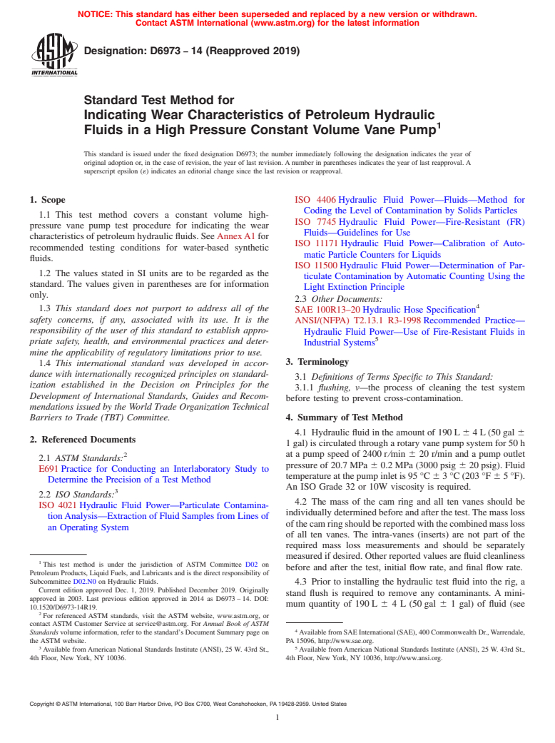
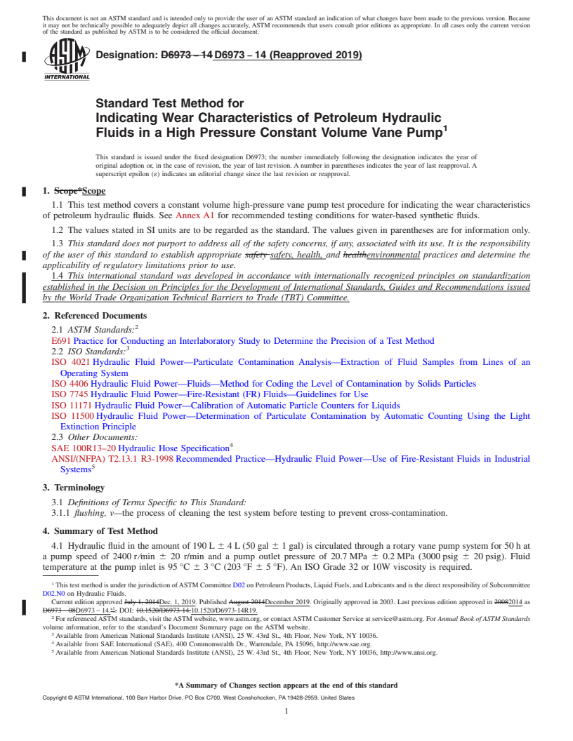
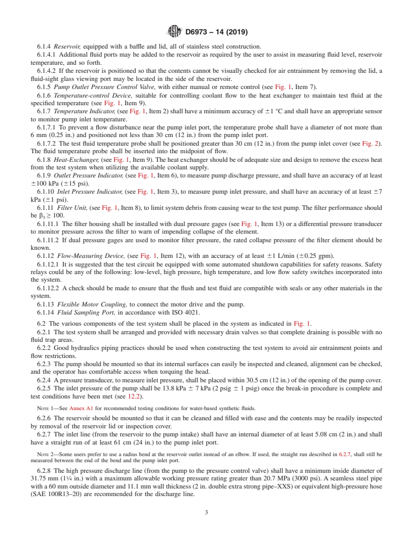
1.1 This test method covers a constant volume high-pressure vane pump test procedure for indicating the wear characteristics of petroleum hydraulic fluids. See Annex A1 for recommended testing conditions for water-based synthetic fluids.
1.2 The values stated in SI units are to be regarded as the standard. The values given in parentheses are for information only.
1.3 This standard does not purport to address all of the safety concerns, if any, associated with its use. It is the responsibility of the user of this standard to establish appropriate safety, health, and environmental practices and determine the applicability of regulatory limitations prior to use.
1.4 This international standard was developed in accordance with internationally recognized principles on standardization established in the Decision on Principles for the Development of International Standards, Guides and Recommendations issued by the World Trade Organization Technical Barriers to Trade (TBT) Committee.
General Information
Buy Standard
Standards Content (Sample)
NOTICE: This standard has either been superseded and replaced by a new version or withdrawn.
Contact ASTM International (www.astm.org) for the latest information
Designation: D6973 − 14 (Reapproved 2019)
Standard Test Method for
Indicating Wear Characteristics of Petroleum Hydraulic
Fluids in a High Pressure Constant Volume Vane Pump
This standard is issued under the fixed designation D6973; the number immediately following the designation indicates the year of
original adoption or, in the case of revision, the year of last revision. A number in parentheses indicates the year of last reapproval. A
superscript epsilon (´) indicates an editorial change since the last revision or reapproval.
1. Scope ISO 4406 Hydraulic Fluid Power—Fluids—Method for
Coding the Level of Contamination by Solids Particles
1.1 This test method covers a constant volume high-
ISO 7745 Hydraulic Fluid Power—Fire-Resistant (FR)
pressure vane pump test procedure for indicating the wear
Fluids—Guidelines for Use
characteristicsofpetroleumhydraulicfluids.SeeAnnexA1for
ISO 11171 Hydraulic Fluid Power—Calibration of Auto-
recommended testing conditions for water-based synthetic
matic Particle Counters for Liquids
fluids.
ISO 11500 Hydraulic Fluid Power—Determination of Par-
1.2 The values stated in SI units are to be regarded as the
ticulate Contamination by Automatic Counting Using the
standard. The values given in parentheses are for information
Light Extinction Principle
only.
2.3 Other Documents:
1.3 This standard does not purport to address all of the
SAE 100R13–20 Hydraulic Hose Specification
safety concerns, if any, associated with its use. It is the
ANSI/(NFPA) T2.13.1 R3-1998 Recommended Practice—
responsibility of the user of this standard to establish appro-
Hydraulic Fluid Power—Use of Fire-Resistant Fluids in
priate safety, health, and environmental practices and deter-
Industrial Systems
mine the applicability of regulatory limitations prior to use.
3. Terminology
1.4 This international standard was developed in accor-
dance with internationally recognized principles on standard-
3.1 Definitions of Terms Specific to This Standard:
ization established in the Decision on Principles for the
3.1.1 flushing, v—the process of cleaning the test system
Development of International Standards, Guides and Recom-
before testing to prevent cross-contamination.
mendations issued by the World Trade Organization Technical
Barriers to Trade (TBT) Committee. 4. Summary of Test Method
4.1 Hydraulic fluid in the amount of 190 L 6 4 L(50 gal 6
2. Referenced Documents
1 gal) is circulated through a rotary vane pump system for 50 h
2 at a pump speed of 2400 r⁄min 6 20 r/min and a pump outlet
2.1 ASTM Standards:
pressure of 20.7 MPa 6 0.2 MPa (3000 psig 6 20 psig). Fluid
E691 Practice for Conducting an Interlaboratory Study to
temperatureatthepumpinletis95 °C 63 °C(203 °F 65 °F).
Determine the Precision of a Test Method
An ISO Grade 32 or 10W viscosity is required.
2.2 ISO Standards:
4.2 The mass of the cam ring and all ten vanes should be
ISO 4021 Hydraulic Fluid Power—Particulate Contamina-
individuallydeterminedbeforeandafterthetest.Themassloss
tionAnalysis—Extraction of Fluid Samples from Lines of
ofthecamringshouldbereportedwiththecombinedmassloss
an Operating System
of all ten vanes. The intra-vanes (inserts) are not part of the
required mass loss measurements and should be separately
measured if desired. Other reported values are fluid cleanliness
This test method is under the jurisdiction of ASTM Committee D02 on
before and after the test, initial flow rate, and final flow rate.
Petroleum Products, Liquid Fuels, and Lubricants and is the direct responsibility of
Subcommittee D02.N0 on Hydraulic Fluids.
4.3 Prior to installing the hydraulic test fluid into the rig, a
Current edition approved Dec. 1, 2019. Published December 2019. Originally
stand flush is required to remove any contaminants. A mini-
approved in 2003. Last previous edition approved in 2014 as D6973 – 14. DOI:
mum quantity of 190 L 6 4 L (50 gal 6 1 gal) of fluid (see
10.1520/D6973-14R19.
For referenced ASTM standards, visit the ASTM website, www.astm.org, or
contact ASTM Customer Service at service@astm.org. For Annual Book of ASTM
Standards volume information, refer to the standard’s Document Summary page on Available from SAE International (SAE), 400 Commonwealth Dr.,Warrendale,
the ASTM website. PA 15096, http://www.sae.org.
3 5
Available fromAmerican National Standards Institute (ANSI), 25 W. 43rd St., Available fromAmerican National Standards Institute (ANSI), 25 W. 43rd St.,
4th Floor, New York, NY 10036. 4th Floor, New York, NY 10036, http://www.ansi.org.
Copyright © ASTM International, 100 Barr Harbor Drive, PO Box C700, West Conshohocken, PA 19428-2959. United States
D6973 − 14 (2019)
Description of Components:
1 Reservoir, 190 L (50 gal) of oil; elevated above pump centerline to provide gravity feed
2 Temperature gage or thermocouple
3 Inlet pressure gage
4 Pump: 35VQ25A-11*20 (Cartridge kit P/N 4998040–002)
5 Electric motor, 93 kW (125 hp)
6 Outlet pressure gage
7 Pressure relief valve
8 Filter
9 Cooler
10 Flowmeter
NOTE 1—See Eaton Overhaul Manual I-3144–S (Appendix B) (available from any Eaton distributor).
FIG. 1 System Schematic
6,7
Note 1) made of the same chemical formulation as the test 6.1.3 Rotary Intra-Vane Pump,replaceablecartridgetype,
fluid,isrequiredforthestandflush.Thereforethetotalquantity Vickers 35VQ25A-11*20 (Cartridge Kit P/N 4998040-002)
3 3
of oil required for the test is 380 L (100 gal). rated at 81 cm /rev (4.98 in. /rev) flow at 1200 r/min. A
protective shield around the pump is recommended.
5. Significance and Use
6.1.3.1 There are to be no modifications to the pump
housing.
5.1 This test method is an indicator of the wear character-
istics of petroleum hydraulic fluids operating in a constant
volume vane pump. Excessive wear in vane pumps could lead
The replaceable cartridge consists of the inlet support plate, outlet support
to malfunction of hydraulic systems in critical industrial or
plate, flex side plates, seal pack, rotor, cam ring, intra-vane, and vanes.
mobile hydraulic applications.
The individual cartridge parts can be purchased separately, if desired. The
Eaton part numbers for these items are cartridge screws: P/N 410609, alignment
6. Apparatus
pins:P/N418108,inletsupportplate:P/N430806,outletsupportplate:P/N412003,
flexsideplatekit:P/N923953,sealpack:P/N433766,rotor:P/N262154,camring:
6.1 The basic system consists of the following (see Fig. 1):
P/N 4999594-001, vane kit (includes ten intra-vanes and ten vanes): 922700.
6.1.1 Electric Motor, or other suitable drive, capable of a
Available from any Eaton distributor.
The sole source of supply of the apparatus known to the committee at this time
rotational speed of 2400 r/min with 93 kW (125 hp) as
is Eaton, 14615 Lone Oak Rd., Eden Prairie, MN 55344, http://www.eaton.com. If
suggested minimum power requirement (see Fig. 1, Item 5).
you are aware of alternative suppliers, please provide this information to ASTM
6.1.2 Test Stand Base, with appropriate, rigid mounting for
International Headquarters. Your comments will receive careful consideration at a
the motor, pump, reservoir, and other components. meeting of the responsible technical committee, which you may attend.
D6973 − 14 (2019)
NOTE 1—See Eaton Overhaul Manual I-3144–S (Appendix C) (available from any Eaton distributor).
FIG. 2 Pump Components
6.1.4 Reservoir, equipped with a baffle and lid, all of 6.1.6 Temperature-control Device, suitable for controlling
stainless steel construction.
coolant flow to the heat exchanger to maintain test fluid at the
6.1.4.1 Additional fluid ports may be added to the reservoir
specified temperature (see Fig. 1, Item 9).
as required by the user to assist in measuring fluid level,
6.1.7 Temperature Indicator, (see Fig. 1, Item 2) shall have
reservoir temperature, and so forth.
a minimum accuracy of 61 °C and shall have an appropriate
6.1.4.2 If the reservoir is positioned so that the contents
sensor to monitor pump inlet temperature.
cannotbevisuallycheckedforairentrainmentbyremovingthe
6.1.7.1 To prevent a flow disturbance near the pump inlet
lid, a fluid-sight glass viewing port may be located in the side
port, the temperature probe shall have a diameter of not more
of the reservoir.
than6mm(0.25in.)andpositionednotlessthan30cm(12in.)
6.1.5 Pump Outlet Pressure Control Valve, with either
from the pump inlet port.
manual or remote control (see Fig. 1, Item 7).
D6973 − 14 (2019)
6.1.7.2 The test fluid temperature probe shall be positioned 6.2.6 The reservoir should be mounted so that it can be
greater than 30 cm (12 in.) from the pump inlet cover (see Fig. cleaned and filled with ease and the contents may be readily
2). The fluid temperature probe shall be inserted into the inspected by removal of the reservoir lid or inspection cover.
midpoint of flow. 6.2.7 The inlet line (from the reservoir to the pump intake)
shall have an internal diameter of at least 5.08 cm (2 in.) and
6.1.8 Heat-Exchanger, (see Fig. 1, Item 9). The heat ex-
shall have a straight run of at least 61 cm (24 in.) to the pump
changer should be of adequate size and design to remove the
inlet port.
excess heat from the test system when utilizing the available
coolant supply.
NOTE 2—Some users prefer to use a radius bend at the reservoir outlet
6.1.9 Outlet Pressure Indicator, (see Fig. 1, Item 6), to
instead of an elbow. If used, the straight run described in 6.2.7, shall still
measure pump discharge pressure, and shall have an accuracy be measured between the end of the bend and the pump inlet port.
of at least 6100 kPa (615 psi).
6.2.8 Thehighpressuredischargeline(fromthepumptothe
6.1.10 Inlet Pressure Indicator, (see Fig. 1, Item 3), to
pressure control valve) shall have a minimum inside diameter
measure pump inlet pressure, and shall have an accuracy of at
of 31.75 mm (1 ⁄4 in.) with a maximum allowable working
least 67 kPa (61 psi).
pressure rating greater than 20.7 MPa (3000 psi). A seamless
6.1.11 FilterUnit,(seeFig.1,Item8),tolimitsystemdebris
steel pipe with a 60 mm outside diameter and 11.1 mm wall
from causing wear to the test pump. The filter performance thickness (2 in. double extra strong pipe–XXS) or equivalent
should be β ≥ 100.
high-pressure hose (SAE 100R13–20) are recommended for
6.1.11.1 The filter housing shall be installed with dual the discharge line.
pressure gages (see Fig. 1, Item 13) or a differential pressure 6.2.9 The fluid return line and fittings (from the pressure
transducer to monitor pressure across the filter to warn of control valve to the filter, flowmeter, heat exchanger, and
impending collapse of the element. reservoir) should have a minimum inside diameter of 2.54 cm
(1 in.).Aseamless steel pipe with 33 mm outside diameter and
6.1.11.2 If dual pressure gages are used to monitor filter
3.4 mm wall thickness (1 in. Schedule 40) is recommended for
pressure,theratedcollapsepressureofthefilterelementshould
the fluid return line.
be known.
6.2.10 A shut-off valve may be located in the plumbing
6.1.12 Flow-Measuring Device, (see Fig. 1, Item 12), with
between the reservoir and the inlet to the pump. The full flow
an accuracy of at least 61 L/min (60.25 gpm).
valve shall have a minimum orifice diameter of 5.08 cm (2 in.)
6.1.12.1 It is suggested that the test circuit be equipped with
and shall be positioned no closer than 30 cm (12 in.) from the
some automated shutdown capabilities for safety reasons.
pump inlet port.
Safety relays could be any of the following: low-level, high
pressure, high temperature, and low flow safety switches
NOTE 3—Some users find the addition of a shut-off valve on the return
incorporated into the system.
line to be a useful addition to the piping since it allows filter changes and
other system maintenance to be performed without draining the reservoir.
6.1.12.2 Acheckshouldbemadetoensurethattheflushand
(Warning—If a shut-off valve is installed in the fluid return line, the user
testfluidarecompatiblewithsealsoranyothermaterialsinthe
shalltakeproceduralstepstoensurethatthisvalvehasbeenopenedbefore
system.
the pump is started. If the valve is not opened, low pressure system
6.1.13 Flexible Motor Coupling, to connect the motor drive
components may rupture.)
and the pump.
6.1.14 Fluid Sampling Port, in accordance with ISO 4021. 7. Reagents and Materials
7.1 (Warning—Use adequate safety provisions with all
6.2 The various components of the test system shall be
solvents.)
placed in the system as indicated in Fig. 1.
6.2.1 The test system shall be arranged and provided with
7.2 Aliphatic Naphtha, Stoddard solvent or equivalent is
necessary drain valves so that complete draining is possible
satisfactory. (Warning—Combustible. Vapor harmful.)
with no fluid trap areas.
7.3 Precipitation Naphtha. (Warning—Extremely flam-
6.2.2 Goodhydraulicspipingpracticesshouldbeusedwhen
mable. Harmful if inhaled. Vapors can cause flash fire.)
constructingthetestsystemtoavoidairentrainmentpointsand
7.4 Isopropanol. (Warning—Flammable, vapor harmful in
flow restrictions.
large amounts, eye irritant, extremely combustible when hot.)
6.2.3 The pump should be mounted so that its internal
(Warning—In instances when the solvents listed in Section 7
surfaces can easily be inspected and cleaned, alignment can be
are not effective, alternative solvents may be used. It is the
checked, and the operator has comfortable access when torqu-
responsibility of the user to determine the suitability of
ing the head.
alternative solvents and any hazards associated with their use.)
6.2.4 Apressure transducer, to measure inlet pressure, shall
be placed within 30.5 cm (12 in.) of the opening of the pump
8. Test Stand Maintenance
cover.
8.1 Temperature, pressure, flow sensors and shut-off
6.2.5 The inlet pressure of the pump shall be 13.8 kPa 6
switches shall be checked periodically for proper calibration
7 kPa (2 psig 6 1 psig) once the break-in procedure is
and operation in accordance with good engineering practice, as
complete and test conditions have been met (see 12.2).
determined by the user.
NOTE 1—See Annex A1 for recommended testing conditions for
water-based synthetic fluids. NOTE 4—If an axial turbine flowmeter is used, calibrate with 0.876
D6973 − 14 (2019)
specific gravity, ISO Grade 32 hydraulic oil. Perform a 10-point calibra-
new filter, flush cartridge (any new or used pump cartridge)
tion over a ranges of 0 L⁄min to 227 L⁄min (0 gpm to 50 gpm). This
with 190 L 6 4 L (50 gal 6 1 gal) of the test fluid (ISO VG
calibration shall be performed by the flowmeter manufacturer or other
32).
qualified personnel.
10.2.3 Allow the system to flush for a minimum of 30 min
8.2 It is recommended that the pump shaft (P\N
...
This document is not an ASTM standard and is intended only to provide the user of an ASTM standard an indication of what changes have been made to the previous version. Because
it may not be technically possible to adequately depict all changes accurately, ASTM recommends that users consult prior editions as appropriate. In all cases only the current version
of the standard as published by ASTM is to be considered the official document.
Designation: D6973 − 14 D6973 − 14 (Reapproved 2019)
Standard Test Method for
Indicating Wear Characteristics of Petroleum Hydraulic
Fluids in a High Pressure Constant Volume Vane Pump
This standard is issued under the fixed designation D6973; the number immediately following the designation indicates the year of
original adoption or, in the case of revision, the year of last revision. A number in parentheses indicates the year of last reapproval. A
superscript epsilon (´) indicates an editorial change since the last revision or reapproval.
1. Scope*Scope
1.1 This test method covers a constant volume high-pressure vane pump test procedure for indicating the wear characteristics
of petroleum hydraulic fluids. See Annex A1 for recommended testing conditions for water-based synthetic fluids.
1.2 The values stated in SI units are to be regarded as the standard. The values given in parentheses are for information only.
1.3 This standard does not purport to address all of the safety concerns, if any, associated with its use. It is the responsibility
of the user of this standard to establish appropriate safety safety, health, and healthenvironmental practices and determine the
applicability of regulatory limitations prior to use.
1.4 This international standard was developed in accordance with internationally recognized principles on standardization
established in the Decision on Principles for the Development of International Standards, Guides and Recommendations issued
by the World Trade Organization Technical Barriers to Trade (TBT) Committee.
2. Referenced Documents
2.1 ASTM Standards:
E691 Practice for Conducting an Interlaboratory Study to Determine the Precision of a Test Method
2.2 ISO Standards:
ISO 4021 Hydraulic Fluid Power—Particulate Contamination Analysis—Extraction of Fluid Samples from Lines of an
Operating System
ISO 4406 Hydraulic Fluid Power—Fluids—Method for Coding the Level of Contamination by Solids Particles
ISO 7745 Hydraulic Fluid Power—Fire-Resistant (FR) Fluids—Guidelines for Use
ISO 11171 Hydraulic Fluid Power—Calibration of Automatic Particle Counters for Liquids
ISO 11500 Hydraulic Fluid Power—Determination of Particulate Contamination by Automatic Counting Using the Light
Extinction Principle
2.3 Other Documents:
SAE 100R13–20 Hydraulic Hose Specification
ANSI/(NFPA) T2.13.1 R3-1998 Recommended Practice—Hydraulic Fluid Power—Use of Fire-Resistant Fluids in Industrial
Systems
3. Terminology
3.1 Definitions of Terms Specific to This Standard:
3.1.1 flushing, v—the process of cleaning the test system before testing to prevent cross-contamination.
4. Summary of Test Method
4.1 Hydraulic fluid in the amount of 190 L 6 4 L (50 gal 6 1 gal) is circulated through a rotary vane pump system for 50 h at
a pump speed of 2400 r ⁄min 6 20 r/min and a pump outlet pressure of 20.7 MPa 6 0.2 MPa (3000 psig 6 20 psig). Fluid
temperature at the pump inlet is 95 °C 6 3 °C (203 °F 6 5 °F). An ISO Grade 32 or 10W viscosity is required.
This test method is under the jurisdiction of ASTM Committee D02 on Petroleum Products, Liquid Fuels, and Lubricants and is the direct responsibility of Subcommittee
D02.N0 on Hydraulic Fluids.
Current edition approved July 1, 2014Dec. 1, 2019. Published August 2014December 2019. Originally approved in 2003. Last previous edition approved in 20082014 as
ε1
D6973 – 08D6973 – 14. . DOI: 10.1520/D6973-14.10.1520/D6973-14R19.
For referenced ASTM standards, visit the ASTM website, www.astm.org, or contact ASTM Customer Service at service@astm.org. For Annual Book of ASTM Standards
volume information, refer to the standard’s Document Summary page on the ASTM website.
Available from American National Standards Institute (ANSI), 25 W. 43rd St., 4th Floor, New York, NY 10036.
Available from SAE International (SAE), 400 Commonwealth Dr., Warrendale, PA 15096, http://www.sae.org.
Available from American National Standards Institute (ANSI), 25 W. 43rd St., 4th Floor, New York, NY 10036, http://www.ansi.org.
*A Summary of Changes section appears at the end of this standard
Copyright © ASTM International, 100 Barr Harbor Drive, PO Box C700, West Conshohocken, PA 19428-2959. United States
D6973 − 14 (2019)
Description of Components:
1 Reservoir, 190 L (50 gal) of oil; elevated above pump centerline to provide gravity feed
2 Temperature gage or thermocouple
3 Inlet pressure gage
4 Pump: 35VQ25A-11*20 (Cartridge kit P/N 4998040–002)
5 Electric motor, 93 kW (125 hp)
6 Outlet pressure gage
7 Pressure relief valve
8 Filter
9 Cooler
10 Flowmeter
NOTE 1—See Eaton Overhaul Manual I-3144–S (Appendix B) (available from any Eaton distributor).
FIG. 1 System Schematic
4.2 The mass of the cam ring and all ten vanes should be individually determined before and after the test. The mass loss of
the cam ring should be reported with the combined mass loss of all ten vanes. The intra-vanes (inserts) are not part of the required
mass loss measurements and should be separately measured if desired. Other reported values are fluid cleanliness before and after
the test, initial flow rate, and final flow rate.
4.3 Prior to installing the hydraulic test fluid into the rig, a stand flush is required to remove any contaminants. A minimum
quantity of 190 L 6 4 L (50 gal 6 1 gal) of fluid (see Note 1) made of the same chemical formulation as the test fluid, is required
for the stand flush. Therefore the total quantity of oil required for the test is 380 L (100 gal).
5. Significance and Use
5.1 This test method is an indicator of the wear characteristics of petroleum hydraulic fluids operating in a constant volume vane
pump. Excessive wear in vane pumps could lead to malfunction of hydraulic systems in critical industrial or mobile hydraulic
applications.
6. Apparatus
6.1 The basic system consists of the following (see Fig. 1):
6.1.1 Electric Motor, or other suitable drive, capable of a rotational speed of 2400 r/min with 93 kW (125 hp) as suggested
minimum power requirement (see Fig. 1, Item 5).
6.1.2 Test Stand Base, with appropriate, rigid mounting for the motor, pump, reservoir, and other components.
6,7 8
6.1.3 Rotary Intra-Vane Pump, replaceable cartridge type, Vickers 35VQ25A-11*20 (Cartridge Kit P/N 4998040-002) rated
3 3
at 81 cm /rev (4.98 in. /rev) flow at 1200 r/min. A protective shield around the pump is recommended.
6.1.3.1 There are to be no modifications to the pump housing.
The replaceable cartridge consists of the inlet support plate, outlet support plate, flex side plates, seal pack, rotor, cam ring, intra-vane, and vanes.
The individual cartridge parts can be purchased separately, if desired. The Eaton part numbers for these items are cartridge screws: P/N 410609, alignment pins: P/N
418108, inlet support plate: P/N 430806, outlet support plate: P/N 412003, flex side plate kit: P/N 923953, seal pack: P/N 433766, rotor: P/N 262154, cam ring: P/N
4999594-001, vane kit (includes ten intra-vanes and ten vanes): 922700.
Available from any Eaton distributor.
The sole source of supply of the apparatus known to the committee at this time is Eaton, 14615 Lone Oak Rd., Eden Prairie, MN 55344, http://www.eaton.com. If you
are aware of alternative suppliers, please provide this information to ASTM International Headquarters. Your comments will receive careful consideration at a meeting of
the responsible technical committee, which you may attend.
D6973 − 14 (2019)
6.1.4 Reservoir, equipped with a baffle and lid, all of stainless steel construction.
6.1.4.1 Additional fluid ports may be added to the reservoir as required by the user to assist in measuring fluid level, reservoir
temperature, and so forth.
6.1.4.2 If the reservoir is positioned so that the contents cannot be visually checked for air entrainment by removing the lid, a
fluid-sight glass viewing port may be located in the side of the reservoir.
6.1.5 Pump Outlet Pressure Control Valve, with either manual or remote control (see Fig. 1, Item 7).
6.1.6 Temperature-control Device, suitable for controlling coolant flow to the heat exchanger to maintain test fluid at the
specified temperature (see Fig. 1, Item 9).
6.1.7 Temperature Indicator, (see Fig. 1, Item 2) shall have a minimum accuracy of 61 °C and shall have an appropriate sensor
to monitor pump inlet temperature.
6.1.7.1 To prevent a flow disturbance near the pump inlet port, the temperature probe shall have a diameter of not more than
6 mm (0.25 in.) and positioned not less than 30 cm (12 in.) from the pump inlet port.
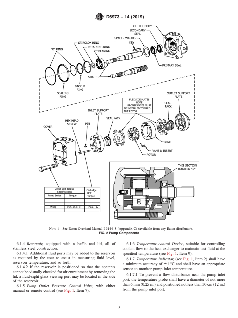
6.1.7.2 The test fluid temperature probe shall be positioned greater than 30 cm (12 in.) from the pump inlet cover (see Fig. 2).
The fluid temperature probe shall be inserted into the midpoint of flow.
6.1.8 Heat-Exchanger, (see Fig. 1, Item 9). The heat exchanger should be of adequate size and design to remove the excess heat
from the test system when utilizing the available coolant supply.
6.1.9 Outlet Pressure Indicator, (see Fig. 1, Item 6), to measure pump discharge pressure, and shall have an accuracy of at least
6100 kPa (615 psi).
6.1.10 Inlet Pressure Indicator, (see Fig. 1, Item 3), to measure pump inlet pressure, and shall have an accuracy of at least 67
kPa (61 psi).
6.1.11 Filter Unit, (see Fig. 1, Item 8), to limit system debris from causing wear to the test pump. The filter performance should
be β ≥ 100.
6.1.11.1 The filter housing shall be installed with dual pressure gages (see Fig. 1, Item 13) or a differential pressure transducer
to monitor pressure across the filter to warn of impending collapse of the element.
6.1.11.2 If dual pressure gages are used to monitor filter pressure, the rated collapse pressure of the filter element should be
known.
6.1.12 Flow-Measuring Device, (see Fig. 1, Item 12), with an accuracy of at least 61 L/min (60.25 gpm).
6.1.12.1 It is suggested that the test circuit be equipped with some automated shutdown capabilities for safety reasons. Safety
relays could be any of the following: low-level, high pressure, high temperature, and low flow safety switches incorporated into
the system.
6.1.12.2 A check should be made to ensure that the flush and test fluid are compatible with seals or any other materials in the
system.
6.1.13 Flexible Motor Coupling, to connect the motor drive and the pump.
6.1.14 Fluid Sampling Port, in accordance with ISO 4021.
6.2 The various components of the test system shall be placed in the system as indicated in Fig. 1.
6.2.1 The test system shall be arranged and provided with necessary drain valves so that complete draining is possible with no
fluid trap areas.
6.2.2 Good hydraulics piping practices should be used when constructing the test system to avoid air entrainment points and
flow restrictions.
6.2.3 The pump should be mounted so that its internal surfaces can easily be inspected and cleaned, alignment can be checked,
and the operator has comfortable access when torquing the head.
6.2.4 A pressure transducer, to measure inlet pressure, shall be placed within 30.5 cm (12 in.) of the opening of the pump cover.
6.2.5 The inlet pressure of the pump shall be 13.8 kPa 6 7 kPa (2 psig 6 1 psig) once the break-in procedure is complete and
test conditions have been met (see 12.2).
NOTE 1—See Annex A1 for recommended testing conditions for water-based synthetic fluids.
6.2.6 The reservoir should be mounted so that it can be cleaned and filled with ease and the contents may be readily inspected
by removal of the reservoir lid or inspection cover.
6.2.7 The inlet line (from the reservoir to the pump intake) shall have an internal diameter of at least 5.08 cm (2 in.) and shall
have a straight run of at least 61 cm (24 in.) to the pump inlet port.
NOTE 2—Some users prefer to use a radius bend at the reservoir outlet instead of an elbow. If used, the straight run described in 6.2.7, shall still be
measured between the end of the bend and the pump inlet port.
6.2.8 The high pressure discharge line (from the pump to the pressure control valve) shall have a minimum inside diameter of
31.75 mm (1 ⁄4 in.) with a maximum allowable working pressure rating greater than 20.7 MPa (3000 psi). A seamless steel pipe
with a 60 mm outside diameter and 11.1 mm wall thickness (2 in. double extra strong pipe–XXS) or equivalent high-pressure hose
(SAE 100R13–20) are recommended for the discharge line.
D6973 − 14 (2019)
NOTE 1—See Eaton Overhaul Manual I-3144–S (Appendix C) (available from any Eaton distributor).
FIG. 2 Pump Components
6.2.9 The fluid return line and fittings (from the pressure control valve to the filter, flowmeter, heat exchanger, and reservoir)
should have a minimum inside diameter of 2.54 cm (1 in.). A seamless steel pipe with 33 mm outside diameter and 3.4 mm wall
thickness (1 in. Schedule 40) is recommended for the fluid return line.
6.2.10 A shut-off valve may be located in the plumbing between the reservoir and the inlet to the pump. The full flow valve
shall have a minimum orifice diameter of 5.08 cm (2 in.) and shall be positioned no closer than 30 cm (12 in.) from the pump inlet
port.
NOTE 3—Some users find the addition of a shut-off valve on the return line to be a useful addition to the piping since it allows filter changes and other
system maintenance to be performed without draining the reservoir. (Warning—If a shut-off valve is installed in the fluid return line, the user shall take
procedural steps to ensure that this valve has been opened before the pump is started. If the valve is not opened, low pressure system components may
rupture.)
D6973 − 14 (2019)
7. Reagents and Materials
7.1 (Warning—Use adequate safety provisions with all solvents.)
7.2 Aliphatic Naphtha, Stoddard solvent or equivalent is satisfactory. (Warning—Combustible. Vapor harmful.)
7.3 Precipitation Naphtha. (Warning—Extremely flammable. Harmful if inhaled. Vapors can cause flash fire.)
7.4 Isopropanol. (Warning—Flammable, vapor harmful in large amounts, eye irritant, extremely combustible when hot.)
(Warning—In instances when the solvents listed in Section 7 are not effective, alternative solvents may be used. It is the
responsibility of the user to determine the suitability of alternative solvents and any hazards associated with their use.)
8. Test Stand Maintenance
8.1 Temperature, pressure, flow sensors and shut-off switches shall be checked periodically for proper calibration and operation
in
...
Questions, Comments and Discussion
Ask us and Technical Secretary will try to provide an answer. You can facilitate discussion about the standard in here.