


ASTM F2661-07(2015)
(Test Method)Standard Test Method for Determining the Tribological Behavior and the Relative Lifetime of a Fluid Lubricant using the Spiral Orbit Tribometer
Standard Test Method for Determining the Tribological Behavior and the Relative Lifetime of a Fluid Lubricant using the Spiral Orbit Tribometer
SIGNIFICANCE AND USE
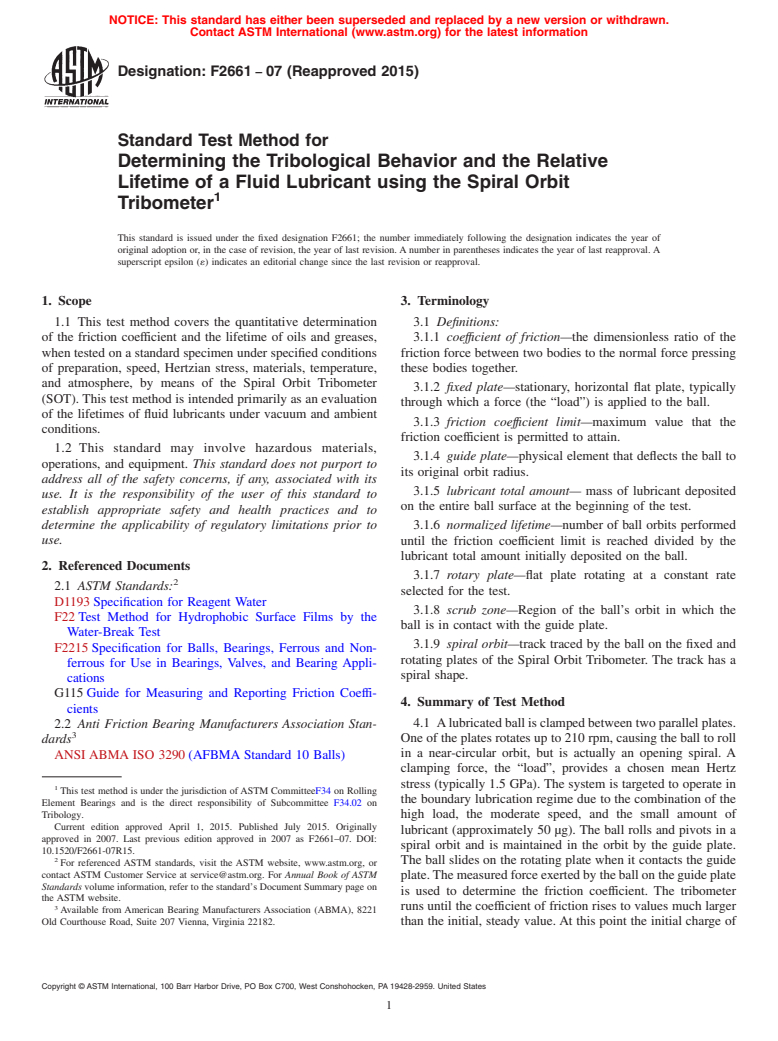
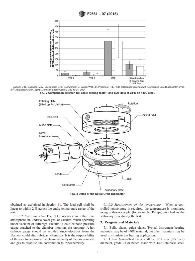
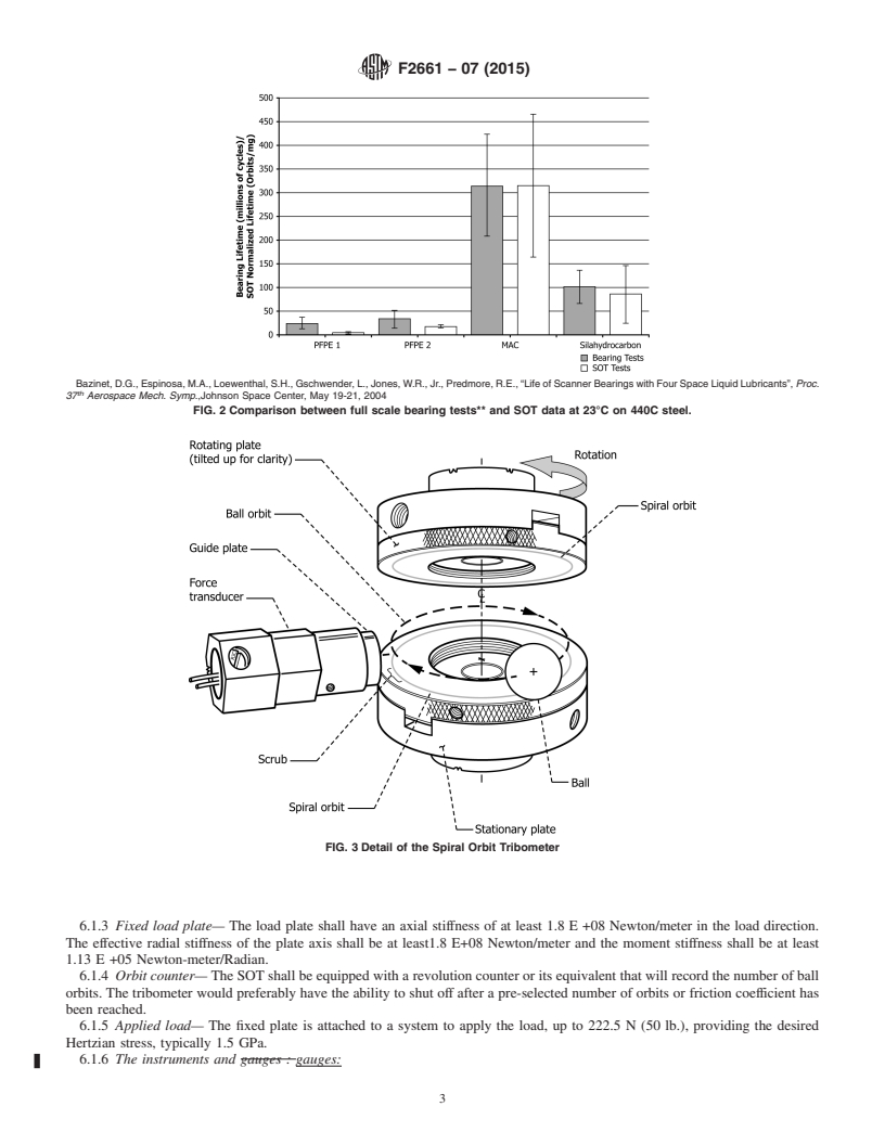
5.1 Relevance of the Spiral Orbit Tribometer (SOT)—The SOT was designed to evaluate the relative degradation rates of liquid lubricants in a contact environment similar to that in an angular contact bearing operating in the boundary lubrication regime. It functions as a screening device to quickly select the lubricants, evaluate the ability of various components of a lubricant (base oil, thickener, or additive) to lubricate a contact in rolling, pivoting, and sliding conditions simultaneously, and study their chemical decomposition if necessary. The SOT provides a means to study the tribological behavior of oils and greases during operation, while they undergo changes as a function of typical parameters encountered in the lubrication field (temperature, environment, materials used, load applied, and speed). Test conclusion is defined to be when a friction coefficient limit (typically an increase of 0.1 above the steady state value) is surpassed. Normalized lubricant lifetime is then defined as the number of orbits completed divided by the initial amount of lubricant used (in μg). The SOT was initially developed to evaluate lubricants for space applications, but is also relevant for conventional environments. Some results in vacuum are presented (Fig. 1). At this time, no data for tests in ambient conditions have been published (see Fig. 2). The user of this test method should determine to their own satisfaction whether results of this test procedure correlate with field performance or other bench test procedures.
Bazinet, D.G., Espinosa, M.A., Loewenthal, S.H., Gschwender, L., Jones, W.R., Jr., Predmore, R.E., “Life of Scanner Bearings with Four Space Liquid Lubricants”, Proc. 37th Aerospace Mech. Symp., Johnson Space Center, May 19-21, 2004
SCOPE
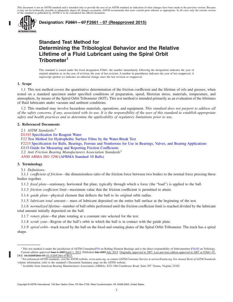
1.1 This test method covers the quantitative determination of the friction coefficient and the lifetime of oils and greases, when tested on a standard specimen under specified conditions of preparation, speed, Hertzian stress, materials, temperature, and atmosphere, by means of the Spiral Orbit Tribometer (SOT). This test method is intended primarily as an evaluation of the lifetimes of fluid lubricants under vacuum and ambient conditions.
1.2 This standard may involve hazardous materials, operations, and equipment. This standard does not purport to address all of the safety concerns, if any, associated with its use. It is the responsibility of the user of this standard to establish appropriate safety and health practices and to determine the applicability of regulatory limitations prior to use.
General Information
Buy Standard
Standards Content (Sample)
NOTICE: This standard has either been superseded and replaced by a new version or withdrawn.
Contact ASTM International (www.astm.org) for the latest information
Designation: F2661 − 07 (Reapproved 2015)
Standard Test Method for
Determining the Tribological Behavior and the Relative
Lifetime of a Fluid Lubricant using the Spiral Orbit
Tribometer
This standard is issued under the fixed designation F2661; the number immediately following the designation indicates the year of
original adoption or, in the case of revision, the year of last revision.Anumber in parentheses indicates the year of last reapproval.A
superscript epsilon (´) indicates an editorial change since the last revision or reapproval.
1. Scope 3. Terminology
1.1 This test method covers the quantitative determination 3.1 Definitions:
of the friction coefficient and the lifetime of oils and greases, 3.1.1 coeffıcient of friction—the dimensionless ratio of the
when tested on a standard specimen under specified conditions friction force between two bodies to the normal force pressing
of preparation, speed, Hertzian stress, materials, temperature, these bodies together.
and atmosphere, by means of the Spiral Orbit Tribometer
3.1.2 fixed plate—stationary, horizontal flat plate, typically
(SOT).This test method is intended primarily as an evaluation
through which a force (the “load”) is applied to the ball.
of the lifetimes of fluid lubricants under vacuum and ambient
3.1.3 friction coeffıcient limit—maximum value that the
conditions.
friction coefficient is permitted to attain.
1.2 This standard may involve hazardous materials,
3.1.4 guide plate—physical element that deflects the ball to
operations, and equipment. This standard does not purport to
its original orbit radius.
address all of the safety concerns, if any, associated with its
3.1.5 lubricant total amount— mass of lubricant deposited
use. It is the responsibility of the user of this standard to
on the entire ball surface at the beginning of the test.
establish appropriate safety and health practices and to
determine the applicability of regulatory limitations prior to 3.1.6 normalized lifetime—number of ball orbits performed
use.
until the friction coefficient limit is reached divided by the
lubricant total amount initially deposited on the ball.
2. Referenced Documents
3.1.7 rotary plate—flat plate rotating at a constant rate
2.1 ASTM Standards:
selected for the test.
D1193Specification for Reagent Water
3.1.8 scrub zone—Region of the ball’s orbit in which the
F22Test Method for Hydrophobic Surface Films by the
ball is in contact with the guide plate.
Water-Break Test
3.1.9 spiral orbit—track traced by the ball on the fixed and
F2215Specification for Balls, Bearings, Ferrous and Non-
rotating plates of the Spiral Orbit Tribometer. The track has a
ferrous for Use in Bearings, Valves, and Bearing Appli-
spiral shape.
cations
G115Guide for Measuring and Reporting Friction Coeffi-
4. Summary of Test Method
cients
4.1 Alubricatedballisclampedbetweentwoparallelplates.
2.2 Anti Friction Bearing Manufacturers Association Stan-
One of the plates rotates up to 210 rpm, causing the ball to roll
dards
in a near-circular orbit, but is actually an opening spiral. A
ANSI ABMA ISO 3290(AFBMA Standard 10 Balls)
clamping force, the “load”, provides a chosen mean Hertz
stress (typically 1.5 GPa). The system is targeted to operate in
This test method is under the jurisdiction ofASTM CommitteeF34 on Rolling
the boundary lubrication regime due to the combination of the
Element Bearings and is the direct responsibility of Subcommittee F34.02 on
Tribology.
high load, the moderate speed, and the small amount of
Current edition approved April 1, 2015. Published July 2015. Originally
lubricant (approximately 50 µg). The ball rolls and pivots in a
approved in 2007. Last previous edition approved in 2007 as F2661–07. DOI:
spiral orbit and is maintained in the orbit by the guide plate.
10.1520/F2661-07R15.
The ball slides on the rotating plate when it contacts the guide
For referenced ASTM standards, visit the ASTM website, www.astm.org, or
contact ASTM Customer Service at service@astm.org. For Annual Book of ASTM
plate.Themeasuredforceexertedbytheballontheguideplate
Standards volume information, refer to the standard’s Document Summary page on
is used to determine the friction coefficient. The tribometer
the ASTM website.
3 runs until the coefficient of friction rises to values much larger
Available from American Bearing Manufacturers Association (ABMA), 8221
Old Courthouse Road, Suite 207 Vienna, Virginia 22182. than the initial, steady value.At this point the initial charge of
Copyright © ASTM International, 100 Barr Harbor Drive, PO Box C700, West Conshohocken, PA 19428-2959. United States
F2661 − 07 (2015)
lubricanthasbeendepletedbytribodegradationandthesystem 6.1.1 General description—Fig. 3 shows a schematic draw-
is running virtually unlubricated. The normalized lifetime is ing of a typical SOT. The system consists of a lubricated ball
obtained from the number of spiral orbits completed before rolling and pivoting between a fixed plate and a rotary plate.
reaching the chosen friction coefficient limit divided by the Theloadisappliedthroughthefixedplate.Thetrackisaspiral
total lubricant mass on the ball at the beginning of the test. A andtheballisreturnedtoitsoriginalorbitradiusbycontacting
minimum of four tests per lubricant and test condition shall be the guide plate, which forces the ball to return to its original
performed. Lubricants can be compared by calculating their radius each orbit. The friction coefficient is determined by the
average normalized lifetimes for a given set of test conditions. measuring the force on the guide plate when the ball contacts
the guide plate. A piezoelectric force transducer is attached to
5. Significance and Use
the guide plate. This force, divided by twice the normal load,
5.1 Relevance of the Spiral Orbit Tribometer (SOT)—The is the friction coefficient.
SOTwas designed to evaluate the relative degradation rates of
6.1.2 Motor drive— A variable speed motor, capable of
liquid lubricants in a contact environment similar to that in an
constant speed, is required. Rotating plate speeds are typically
−1
angular contact bearing operating in the boundary lubrication
in the range 1 to 210 rpm (0.10 to 22 rad.s ). The effective
regime. It functions as a screening device to quickly select the
stiffness of the axis shall be at least 1.8 E +05 Newton/meter
lubricants, evaluate the ability of various components of a
axial in the load direction, 3.6 E +08 Newton/meter radial and
lubricant(baseoil,thickener,oradditive)tolubricateacontact
1.13 E +05 Newton-meter/Radian moment. The TIR of the
in rolling, pivoting, and sliding conditions simultaneously, and
motor shaft shall be 0.0254 millimeters maximum.
study their chemical decomposition if necessary. The SOT
6.1.3 Fixed load plate— The load plate shall have an axial
provides a means to study the tribological behavior of oils and
stiffness of at least 1.8 E +08 Newton/meter in the load
greases during operation, while they undergo changes as a
direction.Theeffectiveradialstiffnessoftheplateaxisshallbe
function of typical parameters encountered in the lubrication
at least1.8 E+08 Newton/meter and the moment stiffness shall
field (temperature, environment, materials used, load applied,
be at least 1.13 E +05 Newton-meter/Radian.
and speed). Test conclusion is defined to be when a friction
6.1.4 Orbit counter— The SOT shall be equipped with a
coefficient limit (typically an increase of 0.1 above the steady
revolutioncounteroritsequivalentthatwillrecordthenumber
state value) is surpassed. Normalized lubricant lifetime is then
of ball orbits.The tribometer would preferably have the ability
definedasthenumberoforbitscompleteddividedbytheinitial
to shut off after a pre-selected number of orbits or friction
amount of lubricant used (in µg). The SOT was initially
coefficient has been reached.
developed to evaluate lubricants for space applications, but is
6.1.5 Applied load— The fixed plate is attached to a system
also relevant for conventional environments. Some results in
to apply the load, up to 222.5 N (50 lb.), providing the desired
vacuum are presented (Fig. 1).At this time, no data for tests in
Hertzian stress, typically 1.5 GPa.
ambient conditions have been published (see Fig. 2). The user
6.1.6 The instruments and gauges:
of this test method should determine to their own satisfaction
whether results of this test procedure correlate with field 6.1.6.1 Friction force— The friction coefficient is deter-
performance or other bench test procedures. mined by measuring the force on the guide plate while the ball
contacts the guide plate. This force is measured using a
6. Apparatus
piezoelectric force transducer and a charge amplifier. The
friction force and the coefficient of friction can then be
6.1 The Spiral Orbit Tribometer (SOT)—See Fig. 3.
Pepper, S.V., Kingsbury, E.P., “Spiral Orbit Tribometry – Part II: Evaluation of Three Liquid Lubricants in Vacuum”, Tribo. Trans., V 46, 1, pp 65-69, 2003
FIG. 1 Relative lifetimes of three typical space lubricants at 23°C in vacuum on 52100 steel
F2661 − 07 (2015)
Bazinet,D.G.,Espinosa,M.A.,Loewenthal,S.H.,Gschwender,L.,Jones,W.R.,Jr.,Predmore,R.E.,“LifeofScannerBearingswithFourSpaceLiquidLubricants”, Proc.
th
37 Aerospace Mech. Symp., Johnson Space Center, May 19-21, 2004
FIG. 2 Comparison between full scale bearing tests** and SOT data at 23°C on 440C steel.
FIG. 3 Detail of the Spiral Orbit Tribometer
obtained as explained in Section 11. The load cell shall be 6.1.6.3 Measurement of the temperature —When a con-
linear to within 2% across the entire temperature range of the trolled temperature is required, the temperature is monitored
test. using a thermocouple (for example, K-type) attached to the
6.1.6.2 Environment— The SOT operates in either one stationary disk during the test.
atmosphere air, under a cover gas, or vacuum.When operating
7. Reagents and Materials
under vacuum or ultrahigh vacuum, a cold cathode pressure
gauge attached to the chamber monitors the pressure. A hot 7.1 Balls, plates, guide plates. Typical instrument bearing
cathode gauge should be avoided since electrons from the materials may be of 440C material, but other materials may be
filament could alter lubricant chemistry. It is the responsibility used to simulate the bearing application.
oftheusertodeterminethechemicalpurityoftheenvironment 7.1.1 Test balls—Test balls shall be 12.7 mm (0.5 inch)
and gas to establish the contribution to tribochemistry. diameter, grade 25 or better, made with 440C stainless steel.
F2661 − 07 (2015)
Their recommended Rockwell hardness shall be 58 to 62. See such as Test Method F22 using reagent grade water per
Specification F2215 or ANSI ABMA ISO 3290 (AFBMA Specification D1193, or a wettability test using the intended
Standard 10) for ball specification reference. Other materials oil. Since many variations of cleaning methods exist and their
may be used to simulate specific application chemistry. results may have a strong effect on the results, it is the user’s
7.1.2 Plates, Guide plates—The fixed plate and the rotary responsibility to determine the effectiveness and safety of the
plate are disks of 50.8 mm (2 inch) in diameter, may be made cleaning methods. The details of the cleaning methods shall
with 440C stainless steel, or any desired material. Surface described in the test report.
roughness of 0.05 mm average roughness or less is recom-
10.2 Lubrication of the balls—Lubricationofthetestsystem
mended. The guide plates are small cylinders 12.7 mm (0.5
is to the ball only.The objective is to lubricate the balls with a
inch in diameter), with a polished surface of 0.05 mm average
small and controlled amount of lubricant.The target amount is
roughness or less (recommended). The recommended Rock-
ascloseaspossibleto50+/−2µgfora12.7mmdiameterball.
well hardness for 440Cshallbe58to62.Stationary androtary
10.2.1 Lubrication of the balls with oil:
plates should be made with the same material. Any bearing
10.2.1.1 Preparation of a dilute solution of oil:
material can be used, depending on the application being
(1) Choose a solvent suitable for the oil to be tested. The
simulated. The recommended values should be used unless
user must determine that the solvent does not harm the sample
differences are required to simulate a specific application.
surface or alter the lubricant.
7.1.3 Care must be taken in surface preparation and han-
(2) Weigh a clean, dry and empty bottle.
dling to avoid surface damage or contamination after cleaning
(3) Put a small drop of oil within the bottle.
that alters the material. Typical cleaning methods may be used
(4) Note the mass of oil (m ) in milligrams.
oil
whentheresultswillpassanTestMethodF22standardtestfor
(5) Add a volume of solvent in the bottle to obtain the
wetability and do not damage the materials or adversely alter
proportion of one milliliter of solvent per one milligram of oil.
the sample surfaces. A wettability test using the intended
(6) Close the bottle and shake it to create an homogeneous
lubricant to evaluate the ball and plate cleaning method is
solution.
recommended.
It is the responsibility of the user to determine the type of
7.1.4 Reagent grade chemicals shall be used per Test
solvent used. Some solvents may not produce a homogeneous
Method F22 section 8.1. It is the user’s responsibility to
solution and can have an adverse effect on the results. Care
preventcontaminationoradulterationofthelubricantsamples,
must be taken to produce a final lubricant film that is
and prevent materials used to clean or lubricate from harming
unadulterated on the ball.
the samples.
10.2.1.2 Lubrication of the ball:
(1)Weigh a dry, clean ball with a micro-balance to 62 µg.
8. Hazards
(2) Fill a micro-syringe with the dilute oil solution.
8.1 Use of solvents— Operator will refer to the safety data
(3)Attach the ball to a handling tool that spins the ball and
sheet of all the solvents used and will take appropriate
start the ball spinning.
precautions.
(4)Putfiftymicroliters,dropbydrop,ofthedilutesolution
8.2 Use of ultrasonic cleaning systems (if applicable)—
on the surface of the spinning ball.
Operator will refer to the instruction manual of the ultrasonic
(5) Wait at least five minutes or until the weight of the
bath before use.
sample is stable to allow the solvent to evaporate.
(6) Remove the ball from the spinning device.
8.3 Use of ultra violet (U.V.)/ozone cleaning system (if
(7) Weigh the lubricated ball with a micro-balance to 62
applicable)—Operator will refer to the instruction manual of
µg.
theU.V./ozonecleaningsystembeforeuse.Specialcarewillbe
(8) Determine the amount of oil, in µg, on the ball and
...
This document is not an ASTM standard and is intended only to provide the user of an ASTM standard an indication of what changes have been made to the previous version. Because
it may not be technically possible to adequately depict all changes accurately, ASTM recommends that users consult prior editions as appropriate. In all cases only the current version
of the standard as published by ASTM is to be considered the official document.
Designation: F2661 − 07 F2661 − 07 (Reapproved 2015)
Standard Test Method for
Determining the Tribological Behavior and the Relative
Lifetime of a Fluid Lubricant using the Spiral Orbit
Tribometer
This standard is issued under the fixed designation F2661; the number immediately following the designation indicates the year of
original adoption or, in the case of revision, the year of last revision. A number in parentheses indicates the year of last reapproval. A
superscript epsilon (´) indicates an editorial change since the last revision or reapproval.
1. Scope
1.1 This test method covers the quantitative determination of the friction coefficient and the lifetime of oils and greases, when
tested on a standard specimen under specified conditions of preparation, speed, Hertzian stress, materials, temperature, and
atmosphere, by means of the Spiral Orbit Tribometer (SOT). This test method is intended primarily as an evaluation of the lifetimes
of fluid lubricants under vacuum and ambient conditions.
1.2 This standard may involve hazardous materials, operations, and equipment. This standard does not purport to address all
of the safety concerns, if any, associated with its use. It is the responsibility of the user of this standard to establish appropriate
safety and health practices and to determine the applicability of regulatory limitations prior to use.
2. Referenced Documents
2.1 ASTM Standards:
D1193 Specification for Reagent Water
F22 Test Method for Hydrophobic Surface Films by the Water-Break Test
F2215 Specification for Balls, Bearings, Ferrous and Nonferrous for Use in Bearings, Valves, and Bearing Applications
G115 Guide for Measuring and Reporting Friction Coefficients
2.2 Anti Friction Bearing Manufacturers Association Standards
ANSI ABMA ISO 3290 (AFBMA Standard 10 Balls)
3. Terminology
3.1 Definitions:
3.1.1 coeffıcient of friction—the dimensionless ratio of the friction force between two bodies to the normal force pressing these
bodies together.
3.1.2 fixed plate—stationary, horizontal flat plate, typically through which a force (the “load”) is applied to the ball.
3.1.3 friction coeffıcient limit—maximum value that the friction coefficient is permitted to attain.
3.1.4 guide plate—physical element that deflects the ball to its original orbit radius.
3.1.5 lubricant total amount— mass of lubricant deposited on the entire ball surface at the beginning of the test.
3.1.6 normalized lifetime—number of ball orbits performed until the friction coefficient limit is reached divided by the lubricant
total amount initially deposited on the ball.
3.1.7 rotary plate—flat plate rotating at a constant rate selected for the test.
3.1.8 scrub zone—Region of the ball’s orbit in which the ball is in contact with the guide plate.
3.1.9 spiral orbit—track traced by the ball on the fixed and rotating plates of the Spiral Orbit Tribometer. The track has a spiral
shape.
This test method is under the jurisdiction of ASTM CommitteeF34 on Rolling Element Bearings and is the direct responsibility of Subcommittee F34.02 on Tribology.
Current edition approved June 1, 2007April 1, 2015. Published July 2007 July 2015. Originally approved in 2007. Last previous edition approved in 2007 as F2661–07.
DOI: 10.1520/F2661-07.10.1520/F2661-07R15.
For referenced ASTM standards, visit the ASTM website, www.astm.org, or contact ASTM Customer Service at service@astm.org. For Annual Book of ASTM Standards
volume information, refer to the standard’s Document Summary page on the ASTM website.
Available from American Bearing Manufacturers Association (ABMA), 8221 Old Courthouse Road, Suite 207 Vienna, Virginia 22182.
Copyright © ASTM International, 100 Barr Harbor Drive, PO Box C700, West Conshohocken, PA 19428-2959. United States
F2661 − 07 (2015)
4. Summary of Test Method
4.1 A lubricated ball is clamped between two parallel plates. One of the plates rotates up to 210 rpm, causing the ball to roll
in a near-circular orbit, but is actually an opening spiral. A clamping force, the “load”, provides a chosen mean Hertz stress
(typically 1.5 GPa). The system is targeted to operate in the boundary lubrication regime due to the combination of the high load,
the moderate speed, and the small amount of lubricant (approximately 50 μg). The ball rolls and pivots in a spiral orbit and is
maintained in the orbit by the guide plate. The ball slides on the rotating plate when it contacts the guide plate. The measured force
exerted by the ball on the guide plate is used to determine the friction coefficient. The tribometer runs until the coefficient of friction
rises to values much larger than the initial, steady value. At this point the initial charge of lubricant has been depleted by
tribodegradation and the system is running virtually unlubricated. The normalized lifetime is obtained from the number of spiral
orbits completed before reaching the chosen friction coefficient limit divided by the total lubricant mass on the ball at the beginning
of the test. A minimum of four tests per lubricant and test condition shall be performed. Lubricants can be compared by calculating
their average normalized lifetimes for a given set of test conditions.
5. Significance and Use
5.1 Relevance of the Spiral Orbit Tribometer (SOT)—The SOT was designed to evaluate the relative degradation rates of liquid
lubricants in a contact environment similar to that in an angular contact bearing operating in the boundary lubrication regime. It
functions as a screening device to quickly select the lubricants, evaluate the ability of various components of a lubricant (base oil,
thickener, or additive) to lubricate a contact in rolling, pivoting, and sliding conditions simultaneously, and study their chemical
decomposition if necessary. The SOT provides a means to study the tribological behavior of oils and greases during operation,
while they undergo changes as a function of typical parameters encountered in the lubrication field (temperature, environment,
materials used, load applied, and speed). Test conclusion is defined to be when a friction coefficient limit (typically an increase
of 0.1 above the steady state value) is surpassed. Normalized lubricant lifetime is then defined as the number of orbits completed
divided by the initial amount of lubricant used (in μg). The SOT was initially developed to evaluate lubricants for space
applications, but is also relevant for conventional environments. Some results in vacuum are presented (Fig. 1). At this time, no
data for tests in ambient conditions have been published (see Fig. 2). The user of this test method should determine to their own
satisfaction whether results of this test procedure correlate with field performance or other bench test procedures.
6. Apparatus
6.1 The Spiral Orbit Tribometer (SOT)—See Fig. 3.
6.1.1 General description—Fig. 3 shows a schematic drawing of a typical SOT. The system consists of a lubricated ball rolling
and pivoting between a fixed plate and a rotary plate. The load is applied through the fixed plate. The track is a spiral and the ball
is returned to its original orbit radius by contacting the guide plate, which forces the ball to return to its original radius each orbit.
The friction coefficient is determined by the measuring the force on the guide plate when the ball contacts the guide plate. A
piezoelectric force transducer is attached to the guide plate. This force, divided by twice the normal load, is the friction coefficient.
6.1.2 Motor drive— A variable speed motor, capable of constant speed, is required. Rotating plate speeds are typically in the
− 1
range 1 to 210 rpm (0.10 to 22 rad.s ). The effective stiffness of the axis shall be at least 1.8 E +05 Newton/meter axial in the
load direction, 3.6 E +08 Newton/meter radial and 1.13 E +05 Newton-meter/Radian moment. The TIR of the motor shaft shall
be 0.0254 millimeters maximum.
Pepper, S.V., Kingsbury, E.P., “Spiral Orbit Tribometry – Part II: Evaluation of Three Liquid Lubricants in Vacuum”, Tribo. Trans., V 46, 1, pp 65-69, 2003
FIG. 1 Relative lifetimes of three typical space lubricants at 23°C in vacuum on 52100 steel
F2661 − 07 (2015)
Bazinet, D.G., Espinosa, M.A., Loewenthal, S.H., Gschwender, L., Jones, W.R., Jr., Predmore, R.E., “Life of Scanner Bearings with Four Space Liquid Lubricants”, Proc.
th
37 Aerospace Mech. Symp.,Johnson Space Center, May 19-21, 2004
FIG. 2 Comparison between full scale bearing tests** and SOT data at 23°C on 440C steel.
FIG. 3 Detail of the Spiral Orbit Tribometer
6.1.3 Fixed load plate— The load plate shall have an axial stiffness of at least 1.8 E +08 Newton/meter in the load direction.
The effective radial stiffness of the plate axis shall be at least1.8 E+08 Newton/meter and the moment stiffness shall be at least
1.13 E +05 Newton-meter/Radian.
6.1.4 Orbit counter— The SOT shall be equipped with a revolution counter or its equivalent that will record the number of ball
orbits. The tribometer would preferably have the ability to shut off after a pre-selected number of orbits or friction coefficient has
been reached.
6.1.5 Applied load— The fixed plate is attached to a system to apply the load, up to 222.5 N (50 lb.), providing the desired
Hertzian stress, typically 1.5 GPa.
6.1.6 The instruments and gauges : gauges:
F2661 − 07 (2015)
6.1.6.1 Friction force— The friction coefficient is determined by measuring the force on the guide plate while the ball contacts
the guide plate. This force is measured using a piezoelectric force transducer and a charge amplifier. The friction force and the
coefficient of friction can then be obtained as explained in Section 11. The load cell shall be linear to within 2 % across the entire
temperature range of the test.
6.1.6.2 Environment— The SOT operates in either one atmosphere air, under a cover gas, or vacuum. When operating under
vacuum or ultrahigh vacuum, a cold cathode pressure gauge attached to the chamber monitors the pressure. A hot cathode gauge
should be avoided since electrons from the filament could alter lubricant chemistry. It is the responsibility of the user to determine
the chemical purity of the environment and gas to establish the contribution to tribochemistry.
6.1.6.3 Measurement of the temperature —When a controlled temperature is required, the temperature is monitored using a
thermocouple (for example, K-type) attached to the stationary disk during the test.
7. Reagents and Materials
7.1 Balls, plates, guide plates. Typical instrument bearing materials may be of 440C material, but other materials may be used
to simulate the bearing application.
7.1.1 Test balls—Test balls shall be 12.7 mm (0.5 inch) diameter, grade 25 or better, made with 440C stainless steel. Their
recommended Rockwell hardness shall be 58 to 62. See Specification F2215 or ANSI ABMA ISO 3290 (AFBMA Standard 10)
for ball specification reference. Other materials may be used to simulate specific application chemistry.
7.1.2 Plates, Guide plates—The fixed plate and the rotary plate are disks of 50.8 mm (2 inch) in diameter, may be made with
440C stainless steel, or any desired material. Surface roughness of 0.05 mm average roughness or less is recommended. The guide
plates are small cylinders 12.7 mm (0.5 inch in diameter), with a polished surface of 0.05 mm average roughness or less
(recommended). The recommended Rockwell hardness for 440C shall be 58 to 62. Stationary and rotary plates should be made
with the same material. Any bearing material can be used, depending on the application being simulated. The recommended values
should be used unless differences are required to simulate a specific application.
7.1.3 Care must be taken in surface preparation and handling to avoid surface damage or contamination after cleaning that alters
the material. Typical cleaning methods may be used when the results will pass an Test Method F22 standard test for wetability and
do not damage the materials or adversely alter the sample surfaces. A wettability test using the intended lubricant to evaluate the
ball and plate cleaning method is recommended.
7.1.4 Reagent grade chemicals shall be used per Test Method F22 section 8.1. It is the user’s responsibility to prevent
contamination or adulteration of the lubricant samples, and prevent materials used to clean or lubricate from harming the samples.
8. Hazards
8.1 Use of solvents— Operator will refer to the safety data sheet of all the solvents used and will take appropriate precautions.
8.2 Use of ultrasonic cleaning systems (if applicable)—Operator will refer to the instruction manual of the ultrasonic bath before
use.
8.3 Use of ultra violet (U.V.)/ozone cleaning system (if applicable)—Operator will refer to the instruction manual of the
U.V./ozone cleaning system before use. Special care will be taken to check the compatibility of the materials used to a U.V. and
ozone exposure.
8.4 Ultrahigh vacuum chamber (if applicable)—The vacuum chamber will be operated with appropriate copper or elastomer
seals to reach ultrahigh vacuum, and will not be opened until the inside of the chamber has reached atmospheric pressure.
9. Sampling, Test Specimens, and Test Units
9.1 Test specimens— Specimens (plates, balls, guide plates) will be kept for further analysis, if required.
9.2 Test units—Only SI units will be used.
10. Procedure
10.1 Cleaning of the parts and tools may be any method that simulates the application. It is recommended that the results of
cleaning procedures are tested using a water break free test such as Test Method F22 using reagent grade water per Specification
D1193, or a wettability test using the intended oil. Since many variations of cleaning methods exist and their results may have a
strong effect on the results, it is the user’s responsibility to determine the effectiveness and safety of the cleaning methods. The
details of the cleaning methods shall described in the test report.
10.2 Lubrication of the balls balls—Lubrication of the test system is to the ball only. The objective is to lubricate the balls with
a small and controlled amount of lubricant. The target amount is as close as possible to 50 +/− 2 μg for a 12.7 mm diameter ball.
10.2.1 Lubrication of the balls with oil—oil:
10.2.1.1 Preparation of a dilute solution of oil:
(1) Choose a solvent suitable for the oil to be tested. The user must determine that the solvent does n
...
Questions, Comments and Discussion
Ask us and Technical Secretary will try to provide an answer. You can facilitate discussion about the standard in here.