


ASTM D3637-84(1991)
(Test Method)Standard Test Methods for Permeability of Bituminous Mixtures (Withdrawn 1998)
Standard Test Methods for Permeability of Bituminous Mixtures (Withdrawn 1998)
General Information
Standards Content (Sample)
--
ASTM D363-i’ 84 - 0759530 050494b 5 m
Designation: D 3637 - 64 (Reapproved 199-l)
Standard Test Methods for
Permbability of Bituminous Mixtures’
This standard is issued under the fixed designation D 3637; the number immediately following the designation indicates the year of
original adoption or, in the case of revision, the year of last revision. A number in parentheses indicates the year of last reapproval. A
superscript epsilon (0 indicates an editorial change since the last revision or reapproval.
1. Scope E 14 1 Recommended Practice for Acceptance of Evidence
Based on the Results of Probability Sampling4
1.1 These test methods cover procedures for determining
the permeability of bituminous mixtures. These methods
3. Significance and Use
measure the rate at which air can be forced (pressure system)
3.1 These methods may be used for a laboratory test for
or drawn (vacuum system) at low pressure through bitumi-
mix design purposes or for a field test for construction
nous mixtures.
control. When testing hot mixes, the pressure system has to
1.2 These test methods cover four different procedures:
be used in order to avoid corrections required to take into
two laboratory tests and two field tests. Field and laboratory
account the expansion and contraction of the air within the
tests can be performed by using either the pressure system or
tubing and pipets.
the vacuum system.
3.2 The following ideal test conditions are prerequisites
1.3 The values stated in inch-pound units are to be
for the laminar flow of air through porous medium under
regarded as the standard. The metric equivalents are ratio-
constant-head conditions:
nalized, rather than exact mathematical conversions. (To
3.2.1 Continuity of flow with no volume change during a
rationalize is to round completely a converted value to a
test,
popular standard figure compatible with noncritical compo-
3.2.2 Flow with the voids fully saturated with the air,
nents, interchangeable parts, or other normal sizes in a
3.2.3 Flow in the steady state with no changes in pressure
series).
gradient, and
1.4 This standard ddes not purport to address all of the 3.2.4 Direct proportionality of velocity of tlo; with pres-
safety problems, if any, associated with its use. It is the sure gradients below certain values, at which tur&lent flow
starts.
responsibility of the user of this standard to establish appro-
3.3 All other types of flow involving partial saturation of
priate safety and health practices and determine the applica-
mix, turbulent flow, and unsteady state of flow are transient
bility of regulatory limitations prior to use.
in character and yield variable and time-dependent perme-
ability; therefore, they require special test conditions and
2. Referenced Documents procedures.
3.4 The use of air for measuring permeability does not
2.1 ASTM Standards:
alter site conditions (or laboratory samples), thus allowing
D 1559 Test Method for Resistance to Plastic Flow of
other measurements on the same site (or the same samples).
Bituminous Mixtures Using Marshall Apparatus2
Furthermore, full saturation is more easily attained with air
D 1560 Test Methods for Resistance to Deformation and
than water and implies much lower pressures. These lower
Cohesion of Bituminous Mixtures by Means of Hveem
pressures eliminate the risks of turbulent flow and reduce the
Apparatuts2
possibility of any volume change during test.
D 156 1 Method for Preparation of Bituminous Mixture
3.5 Through this permeability test, it is possible to eval-
uate rapidly the voids content and the compaction of a
Test Specimens by Means of California Kneading
bituminous mixture even while spreading the mixture; that
CompactorZ
is, when the mix is still hot and there is possibility for further
D 2234 Test Method for Collection of a Gross Sample of
compaction.
Coal3
3.6 Scatter in the test results seems to be mainly due to the
E 105 Practice for Probability Sampling of Materials4
nonhomogeneity of the material rather than the per-
E 122 Practice for Choice of Sample Size to Estimate the
meameter itself.
Average Quality of a Lot or Process4
3.7 These methods may also be used for determining
permeability of alike bituminous materials.
4. Sampling
t These test methods are under the jurisdiction of ASTM Committee D-4 on
Road and Paving Materials and are the direct responsibility of Subcommittee
4.1 In sampling for mix design, select the same samples
D04.23 on Plant-Mix Bituminous Surfaces and Bases.
that will be prepared according to procedures in Methods
Current edition approved March 30, 1984. Published September 1984. Origi-
nally published as D 3637 - 77 T. Last previous edition D 3637 - 80.
D 1559, D 1560, or D 1561.
2 Annual Book of ASTM Standards. VolO4.03.
4.2 In sampling for control on roadway, select the units to
’ Annual Book of ASTM Standards, VolO5.05.
be tested by a random method from the material in place
‘Annual Book of ASTM Standards, Vol 14.02.
after compaction.
ASTM D3637 84 W 0759510 05OV947 7 -
-. .
df#J D 3637
(See Note 4 on Fig. 2
for details)
(Ic) Laboratory Cell Assembly
(See Fig. 3 for details)
WATER RESERVOIQ
(la) Pressure Control Device
(See Fig. 2 for details)
(Id1 Field Cell Assembly
FIG. 1 General Layout of Permeameter
5.1.3. I Laboratory Cell (see Fig. 3, detail 3. l), made of a
4.3 Number and quantities oJsamp/es-The number of
polymethyl methacrylate (PMMA)’ cylinder 10 in. (254
samples required depends on the criticality of, and variation
mm) long, with an inside diameter of 6 in. (150 mm) and a
in, the properties to be measured. Designate each unit from
wall thickness of V2 in. (13 mm). One end of the cylinder is
which a field test is to be obtained prior to sampling. The
closed by a 9’2 in. machined top plate with two G-in.
number of field tests from the production should be sufft-
(6.3-mm) copper fittings screwed to the top plate. A S-in.
cient to give the desired confidence in test results.
thick PMMA retainer collar is fitted into the cylinder 2 in.
NOTE l-Guidance for determining the number of samples required
(50 mm) from the closed end. The inside diameter of the
to obtain the desired level of confidence in test results may be found in
retainer collar is 3 in. (75 mm). The ring is glued firmly and
Method D 2234, and Recommended Practices E 105, E 122, and E 14 1.
air-tight to the cylinder wall. The cylinder is threaded
approximately 6 in. from the open end.
5.1.3.2 Area Ring (see Fig. 3, detail 3.4)-One PMMA
5. Apparatus
ring, l/2 in. (13 mm) thick, with an inside diameter of 3 in.
5.1 Permeameter, capable of measuring air-flow rates of
(75 mm) must be machined to slide closely inside the
up to 5000 mL/min at low-pressure differentials. The general
cylinder.
layout of the permeameter as shown in Fig, 1 is composed of
5.1.3.3 Seal-A G-in. (6.3-mm) thick rubber ring of the
four main parts:
same dimension as the retainer collar is used between the
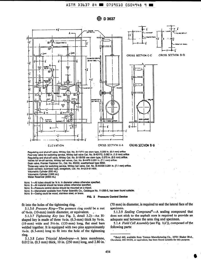
5.1.1 Pressure Control Device (see Fig, l(a) and Fig. 2),
area ring and the retainer collar for sealing purposes.
made with a water reservoir of a capacity of 2000 mL, two
5.1.3.4 Tightening Ring (see Fig. 3, detail 3.5)--A 6-m.
cylinders (one having a capacity of 500 mL and the other
(150-mm) diameter, S-in. (1%mm) thick metal ring is
with a capacity of 1000 mL), a rubber pressure bulb, valves,
threaded to fit the threads of the open end of the laboratory
and calibrated sight tubes (pipets). One sight tube is gradu-
cell. The ring has a 4-in. (1%mm) inside diameter with two
ated in 25-mL increments for dense pavements and the other
%+in. (7.8-mm) holes for receiving a tightening key.
in 500-mL increments for permeable pavements.
X1.3.5 Cross Bar (see Fig. 3, detail 3.3)-A % by %-in.
5.1.2 Stationary Manometer, solid, plastic-inclined style;
(10 by IO-mm) metal bar is provided with a G-in. (6.3-mm)
with a range from 0.10 to 1 .O in. H20 and calibrated to 0.0 1
pin at the center and two G-in. (6.3 mm) pins at the ends to
in. H20 (2.5 Pa) (see Fig. 1( 6)).
5.1.3 Laboratory Cell Assemb& (see Fig. l(c)), composed
5 Plexiglasa. a trademark of Rohm and Haas Co., has been used for this test.
of the following parts:
(’ :
-/
ASTM D3b37 84 - 0759510
0504748 9 m
CROSS SECTION O-D
CROSS SECTION C-C
-CROSS SECTION A-A
ELEVATION cRossxcrloN B-6
Cat. No. 51VF4 vee stem type, 0.250 in. (6.4 mm) c&e
RegulaUng and shut-off valve, Whitey
Four-way valve for switching service, Whltey ball valve Cat. No. E43YF2, 0.062 in. (1.6 mm) orifkx
Cat. No. a-18VS8 vee stem type, 0.375 in. (9.5 mm) orifice.
Reaulatina and shut-off valve, Whiiey
_
Vakes lion-off service, Whitey balivalves, Cat. No. B44F6 0.281 In. (7.1 mm) orifice.
Drain valve, Premier Fastener Co., Cat. No. 65232, weatherhead type 6892.
Three-way valve for switching Serb, Whiiey ball valve, Cat. No. B-44XS6 0.281 in. (7.1 mm) o&a.
.
Quick connact, bulkhead type, swagekxk, Cat. No. B-QCft-B1-600.
Volumetric Cylinder (500 ml)
Volumetric Cylinder (1000 ml)
Water Reservoir (2000 ml)
NOTE l-All tubes shoukl be ‘k in. In diameter unless otherwise specified.
NOTE 2-All material should be brass unless othsiwise spcifted.
NOTE 3-Pressure control device should be mounted on a tripod.
NOTE 4-Manometer available from Fisher scientific Co., Catakqus No. 1 l-295-5, has been found suitable.
NOTE 5-Casing uwld bs wood, stainless stssi, of brass.
FIG. 2 Pressure Control Device
. :
fit into the holes of the tightening ring. (70 mm) in diameter, is required to seal the lateral face of the
specimen.
5.1.3.6 Pressure Ring--The pressure ring could be a nut
5.1.3.9 Sealing Compound”-A sealing compound that
of %-in. (lo-mm) inside diameter, or equivalent. .
does not stick to the asphalt core is required to provide an
5.1.3.7 Tightening Key (see Fig. 3, detail 3.2)-& II&
adequate seal between the area ring and specimen.
shaped key is made of three */4-in. (6.3-mm) thick by %-in.
5.1.4 Field Cell Assembly (see Fig. l(d )), composed of the
(19-mm) wide and 5%in. (133-mm) long, flat steel bars
welded together. It is equipped with two pins approximately following parts:
V&. (6.3-mm) long to fit into the hole of the tightening
ring.
6 Butyl440, available from Tremco Manufacturing Co., 10701 Shaker Blvd.,
5.1.3.8 Latex Triaxial Membrane-A latex membrane,
Cleveland, OH 44104, or equivalent, has been found suitable for this purpoz
0.012 in. (0.3 mm) thick, 10 in. (250 mm) long, and 2.80 in. -
.
ASTM D3b37 84 - 0759530 0504949 0 -
-
~~~_ ~~
dSIE, D 3637
OCTAIL 3.3 - CROSS BAR
DC 1 AIL 3.4 - AREA RING
DCTAIL 3.5 -TIGHTENING R!NG
54----- 6 ----d-L+
MATCRIAL: PLEXIQLAS a.020
MATERIAL t SAC 1020 STEEL
l.)ETAlL 3.1 . LARORATORY CELL
DETAIL 3.2 -TIGHTENING KEY
FIG. 3 Laboratory Cell Details
5.1.4.1 Cup-The cup is a 12-in. (300-mm) diameter by ability; or (b) Use the 500-mL volumetric cylinder for
l-in. (25-mm) thick aluminum plate. Two, V&in. (6.3-mm) pavements with low permeability.
copper tubes are fitted to the plate on top of the 4-in. 6.1.3 Fill the calibrated volumetric cylinder as follows (see
( loo-mm) air chamber. Fig. 3): (a) positioning valve 2 at the vertical, open valve 6,
5.1.4.2 Ring Sealer-A soft rubber ring sealer 4 in. (100
valve 7, and valve 3 (when using 1000 mL volumetric
mm) wide by I/8 in. (3 mm) thick is glued to the cup.
cylinder); and (6) squeeze the rubber bulb to pump air into
5.1.4.3 Weight-A total weight of approximately 60 kg is
the water reservoir. The pressure will force water from the
placed on top of the cup to provide a seal between the
reservoir into the measuring cylinder. The water level is
pavement and rubber ring sealer.
indicated by the calibrated pipet. Continue pumping until
5.2 Thermometers, mercury-type, with a range from 0 to
the calibrated pipet is filled to within approximately 1 in. (25
200°C and a sensitivity of 0.5”C are recommended.
mm) from the top, then close valve 3.
5.3 Barometer, mercury-type, calibrated to 0.01 in. Hg
6.1.4 Close valve 6 and open valve 2 at “Pressure Port”
(35 Pa).
position.
5.4 Stop Watch, with a minimum range of 5 min gradu-
6.1.5 Connect the rubber tubes of the cell as follows (see
ated to 0.1 s. If permeability is smaller than 10-l’ cm, a stop
Fig. 1).
watch of larger range may be required.
6.1.5.1 Pressure System-Connect one of the two rubber
tubes of the cell to the pressure port A and the second tube to
6. Test Procedure
the manometer pressure port B.
6.1.5.2 Vacuum Sy.srem-Connect one of the two rubber
6.1 Preparation of Apparafus:
tubes of the cell to the vacuum port C. Connect the second
6.1.1 Positioning valve 2 (Fig, 3) at exhaust position and
tube of the cell to the manometer vacuum port D.
opening valve 4, fill the reservoir of the pressure control
6.1.6 Level the instrument by observing the level bubble
device with 2000 mL of water using the filling outlet; then
on top of the manometer.
close valve 4.
6.1.2 Select the appropriate cylinder: (a) Use the lOOO- 6.1.7 Set the manometer at the zero reading by sliding the
mL volumetric cylinder for pavements with high perme- scale until the zero reading coincides with the level of the
r
I. ASTM D3b37 84 - 0759530 0504950 7 m
##’ D 3637
manometer fluid, If the fluid level is out of the range of the 6.4.2.4 Place the sealing compound ring on the area ring
so that they are concentric. Press the sealing compound with
scale, it may be necessary to add or withdraw some of the
your hand until it sticks to the area ring.
manometer fluid through the opening plug on top of the
6.4.2.5 Place the area ring with the seal on the surface of
vacuum port.
the sample. Press until the seal adheres uniformly to the
6.2 Method A-Field Testing Usittg the Pressure System:
sample.
6.2.1 Place the field cell on the pavement at the selected
6.4.2.6 Invert the laboratory cell, grasp the sample by the
site and place the 60-kg weight on the cell so that the soft
bottom end, and push the area ring end down into the cell
rubber ring forms a seal around the test area. The instrument
until the area ring rests on the rubber seal ring.
is now ready for the test.
6.4.2.7 Place the pressure ring at the center of the sample
6.2.2 Open valve 3 slowly and adjust the valve opening so
and the crossbar on top, making sure that the pin of the
that a constant pressure is read on the manometer scale.
crossbar is
...
Questions, Comments and Discussion
Ask us and Technical Secretary will try to provide an answer. You can facilitate discussion about the standard in here.