


ASTM C203-05a(2017)
(Test Method)Standard Test Methods for Breaking Load and Flexural Properties of Block-Type Thermal Insulation
Standard Test Methods for Breaking Load and Flexural Properties of Block-Type Thermal Insulation
SIGNIFICANCE AND USE
5.1 These test methods are to be used to determine the resistance of some types of preformed block insulation when transverse loads are normally applied to the surface. Values are measured at the maximum load or breaking point under specified conditions or specimen size, span between supports, and rate of load application. The equations used are based on the assumption that the materials are uniform and presume that the stress-strain characteristics below the elastic limit are linearly elastic. These assumptions are not strictly applicable to thermal insulations of certain types in which crushing occurs before failure is obtained in transverse bending; however, depending upon the accuracy required, these procedures are capable of providing acceptable results.
5.2 Test Method I is especially useful when testing only for the modulus of rupture or the breaking load. This information is useful for quality control inspection and qualification for specification purposes.
5.3 Test Method II is useful in determining the elastic modulus in bending as well as the flexural strength. Flexural properties determined by these test methods are also useful for quality control and specification purposes.
5.4 The basic differences between the two test methods is in the location of the maximum bending moment, maximum axial fiber (flexural or tensile) stresses, and the resolved stress state in terms of shear stress and tensile/compression stress. The maximum axial fiber stresses occur on a line under the loading fitting in Test Method I and over the area between the loading fittings in Test Method II. Test Method I has a high shear stress component in the direction of loading, perpendicular to the axial fiber stress. Sufficient resolved shear stress is capable of producing failure by a shear mode rather than a simple tension/flexural failure. There is no comparable shear component in the central region between the loading fittings in Test Method II. Test Method II simulates a u...
SCOPE
1.1 These test methods cover the determination of the breaking load and calculated flexural strength of a rectangular cross section of a preformed block-type thermal insulation tested as a simple beam. It is also applicable to cellular plastics. Two test methods are described as follows:
1.1.1 Test Method I—A loading system utilizing center loading on a simply supported beam, supported at both ends.
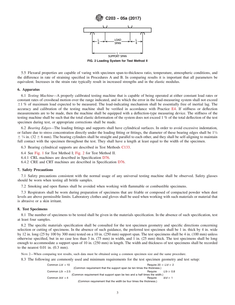
1.1.2 Test Method II—A loading system utilizing two symmetric load points equally spaced from their adjacent support points at each end with a distance between load points of one half of the support span.
1.2 Either test method is capable of being used with the four procedures that follow:
1.2.1 Procedure A—Designed principally for materials that break at comparatively small deflections.
1.2.2 Procedure B—Designed particularly for those materials that undergo large deflections during testing.
1.2.3 Procedure C—Designed for measuring at a constant stress rate, using a CRL (constant rate of loading) machine. Used for breaking load measurements only.
1.2.4 Procedure D—Designed for measurements at a constant crosshead speed, using either a CRT (constant rate of traverse) or CRE (constant rate of extension) machine. Used for breaking load measurements using a fixed crosshead speed machine.
1.3 Comparative tests are capable of being run according to either method or procedure, provided that the method or procedure is found satisfactory for the material being tested.
1.4 These test methods are purposely general in order to accommodate the widely varying industry practices. It is important that the user consult the appropriate materials specification for any specific detailed requirements regarding these test methods.
1.5 The values stated in SI units are to be regarded as the standard. The values given in parentheses are provided for information only.
1.6 This standard does not purport to address all...
General Information
Buy Standard
Standards Content (Sample)
NOTICE: This standard has either been superseded and replaced by a new version or withdrawn.
Contact ASTM International (www.astm.org) for the latest information
Designation: C203 − 05a (Reapproved 2017)
Standard Test Methods for
Breaking Load and Flexural Properties of Block-Type
Thermal Insulation
This standard is issued under the fixed designation C203; the number immediately following the designation indicates the year of
original adoption or, in the case of revision, the year of last revision. A number in parentheses indicates the year of last reapproval. A
superscript epsilon (´) indicates an editorial change since the last revision or reapproval.
This standard has been approved for use by agencies of the U.S. Department of Defense.
1. Scope 1.5 The values stated in SI units are to be regarded as the
standard. The values given in parentheses are provided for
1.1 These test methods cover the determination of the
information only.
breaking load and calculated flexural strength of a rectangular
1.6 This standard does not purport to address all of the
cross section of a preformed block-type thermal insulation
safety concerns, if any, associated with its use. It is the
testedasasimplebeam.Itisalsoapplicabletocellularplastics.
responsibility of the user of this standard to establish appro-
Two test methods are described as follows:
priate safety, health, and environmental practices and deter-
1.1.1 Test Method I—A loading system utilizing center
mine the applicability of regulatory limitations prior to use.
loading on a simply supported beam, supported at both ends.
For specific precautionary statements, see Section 11
1.1.2 Test Method II—A loading system utilizing two sym-
1.7 This international standard was developed in accor-
metric load points equally spaced from their adjacent support
dance with internationally recognized principles on standard-
points at each end with a distance between load points of one
ization established in the Decision on Principles for the
half of the support span.
Development of International Standards, Guides and Recom-
1.2 Either test method is capable of being used with the four
mendations issued by the World Trade Organization Technical
procedures that follow:
Barriers to Trade (TBT) Committee.
1.2.1 Procedure A—Designed principally for materials that
break at comparatively small deflections.
2. Referenced Documents
1.2.2 Procedure B—Designed particularly for those materi-
2.1 ASTM Standards:
als that undergo large deflections during testing.
C133 Test Methods for Cold Crushing Strength and Modu-
1.2.3 Procedure C—Designed for measuring at a constant
lus of Rupture of Refractories
stress rate, using a CRL (constant rate of loading) machine.
C168 Terminology Relating to Thermal Insulation
Used for breaking load measurements only.
C390 Practice for Sampling and Acceptance of Thermal
1.2.4 Procedure D—Designed for measurements at a con-
Insulation Lots
stant crosshead speed, using either a CRT (constant rate of
C870 Practice for Conditioning of Thermal Insulating Ma-
traverse) or CRE (constant rate of extension) machine. Used
terials
for breaking load measurements using a fixed crosshead speed
D76 Specification for Tensile Testing Machines for Textiles
machine.
E4 Practices for Force Verification of Testing Machines
1.3 Comparative tests are capable of being run according to
either method or procedure, provided that the method or
3. Terminology
procedure is found satisfactory for the material being tested.
3.1 Terminology C168 shall be considered applied to the
1.4 These test methods are purposely general in order to
terms used in this method.
accommodate the widely varying industry practices. It is
important that the user consult the appropriate materials
4. Summary of Test Methods
specification for any specific detailed requirements regarding
4.1 A bar of rectangular cross section is tested in flexure as
these test methods.
a beam as follows:
These test methods are under the jurisdiction of ASTM Committee C16 on
Thermal Insulation and are the direct responsibility of Subcommittee C16.32 on
Mechanical Properties. For referenced ASTM standards, visit the ASTM website, www.astm.org, or
Current edition approved Sept. 1, 2017. Published December 2017. Originally contact ASTM Customer Service at service@astm.org. For Annual Book of ASTM
approved in 1945. Last previous edition approved 2012 as C203 – 05a (2012). DOI: Standards volume information, refer to the standard’s Document Summary page on
10.1520/C0203-05AR17. the ASTM website.
Copyright © ASTM International, 100 Barr Harbor Drive, PO Box C700, West Conshohocken, PA 19428-2959. United States
C203 − 05a (2017)
4.1.1 Test Method I—The bar rests on two supports and is
loaded by means of a loading fitting or piece midway between
the supports (see Fig. 1).
4.1.2 Test Method II—The bar rests on two supports and is
loaded at the two quarter points (by means of two loading
fittings), each an equal distance from the adjacent support
point. The distance between the loading fittings is one half of
the support span (see Fig. 2).
FIG. 2 Loading System for Test Method II
4.2 The specimen is deflected until rupture occurs, unless
the materials specification indicates termination at a particular
maximum strain level. is useful for quality control inspection and qualification for
specification purposes.
NOTE 1—One criteria used is to limit the strain to 5 %. If failure does
not occur at 5 % strain, the strain rate is increased and the test repeated on
5.3 Test Method II is useful in determining the elastic
a new specimen.
modulus in bending as well as the flexural strength. Flexural
4.3 Procedures A and B allow for testing at two different properties determined by these test methods are also useful for
strain rates. Procedure C specifies a stress rate. Procedure D quality control and specification purposes.
specifies a rate of extension or traverse.
5.4 The basic differences between the two test methods is in
4.3.1 Procedure A specifies a strain rate of 0.01 in./in.
thelocationofthemaximumbendingmoment,maximumaxial
(mm/mm)thatisusefulfortestinginsulationsthatareverystiff
fiber (flexural or tensile) stresses, and the resolved stress state
or break at quite low deflections.
in terms of shear stress and tensile/compression stress. The
4.3.2 Procedure B specifies a strain rate of 0.1 in./in.
maximum axial fiber stresses occur on a line under the loading
(mm/mm) which is useful for testing insulations that are
fitting in Test Method I and over the area between the loading
relatively flexible or break at higher deflections.
fittings inTest Method II.Test Method I has a high shear stress
4.3.3 Procedure C specifies a stress rate of 550 psi (3.79
component in the direction of loading, perpendicular to the
MPa)/min except as applicable in the materials specification.
axial fiber stress. Sufficient resolved shear stress is capable of
4.3.4 Procedure D specifies a CRE machine with a fixed
producing failure by a shear mode rather than a simple
crosshead speed, or a CRT machine with a movable load
tension/flexural failure. There is no comparable shear compo-
clamp, such as the Scott tester. Because the strain rate is a
nent in the central region between the loading fittings in Test
function of specimen geometry, this procedure does not give a
Method II. Test Method II simulates a uniformly loaded beam
constant strain rate for specimens of different thicknesses
in terms of equivalent stresses at the center of the specimen.
tested on the same loading fixture.
5.5 Flexural properties are capable of varing with specimen
span-to-thickness ratio, temperature, atmospheric conditions,
5. Significance and Use
and the difference in rate of straining specified in ProceduresA
5.1 These test methods are to be used to determine the
and B. In comparing results it is important that all parameters
resistance of some types of preformed block insulation when
be equivalent. Increases in the strain rate typically result in
transverse loads are normally applied to the surface.Values are
increased strengths and in the elastic modulus.
measured at the maximum load or breaking point under
specified conditions or specimen size, span between supports,
6. Apparatus
and rate of load application. The equations used are based on
6.1 TestingMachine—Aproperly calibrated testing machine
the assumption that the materials are uniform and presume that
that is capable of being operated at either constant load rates or
the stress-strain characteristics below the elastic limit are
constant rates of crosshead motion over the range indicated,
linearlyelastic.Theseassumptionsarenotstrictlyapplicableto
and in which the error in the load-measuring system shall not
thermal insulations of certain types in which crushing occurs
exceed 61 % of maximum load expected to be measured. The
before failure is obtained in transverse bending; however,
load-indicating mechanism shall be essentially free of inertial
depending upon the accuracy required, these procedures are
lag. The accuracy and calibration of the testing machine shall
capable of providing acceptable results.
be verified in accordance with Practice E4. If stiffness or
5.2 Test Method I is especially useful when testing only for
deflection measurements are to be made, then the machine
the modulus of rupture or the breaking load. This information
shall be equipped with a deflection-type measuring device.The
stiffness of the testing machine shall be such that the total
elastic deformation of the system does not exceed 1 % of the
total deflection of the test specimen during test, or appropriate
corrections shall be made.
6.2 Bearing Edges—The loading fittings and supports shall
have cylindrical surfaces. In order to avoid excessive
indentation,orfailureduetostressconcentrationdirectlyunder
the loading fitting or fittings, the diameter of these bearing
1 1
FIG. 1 Loading System for Test Method I edgesshallbe1 ⁄4 6 ⁄4in.(32 66mm).Thebearingcylinders
C203 − 05a (2017)
patibility precludes a simple table of commonly used and minimum
shall be straight and parallel to each other, and they shall be
dimensions.
self-aligning to maintain full contact with the specimen
throughout the test. They shall have a length at least equal to 8.4 The selection of the samples shall conform to Practice
the width of the specimen. C390. The specimens shall be cut from larger blocks or
irregular shapes in such a manner to preserve as many of the
6.3 Bearing cylindrical supports are described inTest Meth-
original surfaces as acceptable. Only one sample shall be cut
ods C133.
from a single block or board. Multiple specimens are capable
6.4 See Fig. 1 for Test Method I; Fig. 2 for Test Method II.
of being cut from a sample such as a large bun of insulation
6.4.1 CRL machines are described in Specification D76.
material. If the test specimen is cut to obtain a narrower width
6.4.2 CREandCRTmachines are described in Specification
than as received, the cut shall be made lengthwise of the block.
D76.
For anisotropic materials, flexural tests are capable of being
run in other than the length direction, such as the cross
7. Safety Precautions
directionofthesample.Whencomparativetestsaretobemade
on preformed materials, all specimens shall be of the same
7.1 Safety precautions consistent with the normal usage of
thickness, except as applicable in the materials specification.
any universal testing machine shall be observed. Safety glasses
The bearing faces of the test specimens shall be approximately
should be worn when testing all brittle samples.
parallelplanes.Inpreparingspecimensfrompiecesofirregular
7.2 Smoking and open flames shall be avoided when work-
shape, any means such as a band saw, or any method involving
ing with flammable or combustible specimens.
the use of abrasives such as high-speed abrasion wheel or
7.3 Respirators shall be worn during preparation of speci-
rubbing bed, that will produce a specimen with approximately
mens that are friable or composed of compacted powder when
plane and parallel faces (parallel within 1°) without weakening
dust levels are above permissible limits. Laboratory clothes
the structure of the specimen is capable of being used. The
and gloves shall be used when working with such materials or
valueobtainedonspecimenswithmachinedsurfaceswilldiffer
material that is abrasive or a skin irritant.
from those obtained on specimens with original surfaces.
Consequently, the report must state if original surfaces were
8. Test Specimens
retained and when only one original surface was retained,
whether it was on the tension or compression side of the beam.
8.1 The number of specimens to be tested shall be given in
thematerialsspecification.Intheabsenceofsuchspecification,
9. Conditioning
test at least four samples.
9.1 Dry and condition specimens prior to test, following
8.2 The specific materials specification shall be consulted
applicable specifications for the material. In the absence of
for the test specimen geometry and specific directions concern-
definitive drying specifications, follow accepted practices for
ing selection or cutting of specimens. In the absence of such
conditioning in Practice C870. Where circumstances or re-
guidance, the preferred test specimen shall be 1 in. thick by 4
quirements preclude compliance with these conditioning
in. wide by 12 in. long (25 by 100 by 300 mm) tested on a 10
procedures, exceptions agreed upon between the manufacturer
in. (250 mm) support span. The test specimens shall be 4 in.
and the purchaser shall be made, and will be specifically listed
(100 mm) unless otherwise specified, but in no case less than
in the test report.
3 in. (75 mm) in width, and 1 in. (25 mm) thick. The test
specimens shall be long enough to accommodate a support
10. Procedure
span of 10 in. (250 mm) in length. The width and thickness of
10.1 Test Method I, Procedure A:
test specimens shall be recorded to the nearest 0.01 in. (0.3
10.1.1 Use an untested specimen for each measurement.
mm).
Measure the width and depth of the specimen to the nearest
NOTE 2—When comparing test results, such data must be obtained
0.01 in. (0.3 mm) at the center of the support span. Each
using a common specimen size and the same procedure.
dimension is to be measured at three points along the center
8.3 The following are commonly used and minimum re-
line of the span and to use the average value of these
quirements for the test specimen geometry and test setup:
measurementsinordertogetabettervalueincasethesidesare
Common L/d = 10 Require 20$ L/d$ 2
not truly parallel.
(Common requirement that the support span be ten times the thickness.)
10.1.2 Determine the support span to be used and set up the
Common L/b = 2.5 Require L/b$ 0.8
support span to within 1 % of the determined value. Measure
(Common requirement that support span be two and a half times the
width.)
this support span to the nearest 0.1
...
This document is not an ASTM standard and is intended only to provide the user of an ASTM standard an indication of what changes have been made to the previous version. Because
it may not be technically possible to adequately depict all changes accurately, ASTM recommends that users consult prior editions as appropriate. In all cases only the current version
of the standard as published by ASTM is to be considered the official document.
Designation: C203 − 05a (Reapproved 2012) C203 − 05a (Reapproved 2017)
Standard Test Methods for
Breaking Load and Flexural Properties of Block-Type
Thermal Insulation
This standard is issued under the fixed designation C203; the number immediately following the designation indicates the year of
original adoption or, in the case of revision, the year of last revision. A number in parentheses indicates the year of last reapproval. A
superscript epsilon (´) indicates an editorial change since the last revision or reapproval.
This standard has been approved for use by agencies of the U.S. Department of Defense.
1. Scope
1.1 These test methods cover the determination of the breaking load and calculated flexural strength of a rectangular cross
section of a preformed block-type thermal insulation tested as a simple beam. It is also applicable to cellular plastics. Two test
methods are described as follows:
1.1.1 Test Method I—A loading system utilizing center loading on a simply supported beam, supported at both ends.
1.1.2 Test Method II—A loading system utilizing two symmetric load points equally spaced from their adjacent support points
at each end with a distance between load points of one half of the support span.
1.2 Either test method is capable of being used with the four procedures that follow:
1.2.1 Procedure A—Designed principally for materials that break at comparatively small deflections.
1.2.2 Procedure B—Designed particularly for those materials that undergo large deflections during testing.
1.2.3 Procedure C—Designed for measuring at a constant stress rate, using a CRL (constant rate of loading) machine. Used for
breaking load measurements only.
1.2.4 Procedure D—Designed for measurements at a constant crosshead speed, using either a CRT (constant rate of traverse)
or CRE (constant rate of extension) machine. Used for breaking load measurements using a fixed crosshead speed machine.
1.3 Comparative tests are capable of being run according to either method or procedure, provided that the method or procedure
is found satisfactory for the material being tested.
1.4 These test methods are purposely general in order to accommodate the widely varying industry practices. It is important that
the user consult the appropriate materials specification for any specific detailed requirements regarding these test methods.
1.5 The values stated in SI units are to be regarded as the standard. The values given in parentheses are provided for information
only.
1.6 This standard does not purport to address all of the safety concerns, if any, associated with its use. It is the responsibility
of the user of this standard to establish appropriate safety safety, health, and healthenvironmental practices and determine the
applicability of regulatory limitations prior to use. For specific precautionary statements, see Section 11
1.7 This international standard was developed in accordance with internationally recognized principles on standardization
established in the Decision on Principles for the Development of International Standards, Guides and Recommendations issued
by the World Trade Organization Technical Barriers to Trade (TBT) Committee.
2. Referenced Documents
2.1 ASTM Standards:
C133 Test Methods for Cold Crushing Strength and Modulus of Rupture of Refractories
C168 Terminology Relating to Thermal Insulation
C390 Practice for Sampling and Acceptance of Thermal Insulation Lots
C870 Practice for Conditioning of Thermal Insulating Materials
D76 Specification for Tensile Testing Machines for Textiles
These test methods are under the jurisdiction of ASTM Committee C16 on Thermal Insulation and are the direct responsibility of Subcommittee C16.32 on Mechanical
Properties.
Current edition approved March 1, 2012Sept. 1, 2017. Published May 2012December 2017. Originally approved in 1945. Last previous edition approved 20052012 as
C203 – 05a.C203 – 05a (2012). DOI: 10.1520/C0203-05AR12.10.1520/C0203-05AR17.
For referenced ASTM standards, visit the ASTM website, www.astm.org, or contact ASTM Customer Service at service@astm.org. For Annual Book of ASTM Standards
volume information, refer to the standard’s Document Summary page on the ASTM website.
Copyright © ASTM International, 100 Barr Harbor Drive, PO Box C700, West Conshohocken, PA 19428-2959. United States
C203 − 05a (2017)
E4 Practices for Force Verification of Testing Machines
3. Terminology
3.1 Terminology C168 shall be considered applied to the terms used in this method.
4. Summary of Test Methods
4.1 A bar of rectangular cross section is tested in flexure as a beam as follows:
4.1.1 Test Method I—The bar rests on two supports and is loaded by means of a loading fitting or piece midway between the
supports (see Fig. 1).
4.1.2 Test Method II—The bar rests on two supports and is loaded at the two quarter points (by means of two loading fittings),
each an equal distance from the adjacent support point. The distance between the loading fittings is one half of the support span
(see Fig. 2).
4.2 The specimen is deflected until rupture occurs, unless the materials specification indicates termination at a particular
maximum strain level.
NOTE 1—One criteria used is to limit the strain to 5 %. If failure does not occur at 5 % strain, the strain rate is increased and the test repeated on a
new specimen.
4.3 Procedures A and B allow for testing at two different strain rates. Procedure C specifies a stress rate. Procedure D specifies
a rate of extension or traverse.
4.3.1 Procedure A specifies a strain rate of 0.01 in./in. (mm/mm) that is useful for testing insulations that are very stiff or break
at quite low deflections.
4.3.2 Procedure B specifies a strain rate of 0.1 in./in. (mm/mm) which is useful for testing insulations that are relatively flexible
or break at higher deflections.
4.3.3 Procedure C specifies a stress rate of 550 psi (3.79 MPa)/min except as applicable in the materials specification.
4.3.4 Procedure D specifies a CRE machine with a fixed crosshead speed, or a CRT machine with a movable load clamp, such
as the Scott tester. Because the strain rate is a function of specimen geometry, this procedure does not give a constant strain rate
for specimens of different thicknesses tested on the same loading fixture.
5. Significance and Use
5.1 These test methods are to be used to determine the resistance of some types of preformed block insulation when transverse
loads are normally applied to the surface. Values are measured at the maximum load or breaking point under specified conditions
or specimen size, span between supports, and rate of load application. The equations used are based on the assumption that the
materials are uniform and presume that the stress-strain characteristics below the elastic limit are linearly elastic. These
assumptions are not strictly applicable to thermal insulations of certain types in which crushing occurs before failure is obtained
in transverse bending; however, depending upon the accuracy required, these procedures are capable of providing acceptable
results.
5.2 Test Method I is especially useful when testing only for the modulus of rupture or the breaking load. This information is
useful for quality control inspection and qualification for specification purposes.
5.3 Test Method II is useful in determining the elastic modulus in bending as well as the flexural strength. Flexural properties
determined by these test methods are also useful for quality control and specification purposes.
5.4 The basic differences between the two test methods is in the location of the maximum bending moment, maximum axial
fiber (flexural or tensile) stresses, and the resolved stress state in terms of shear stress and tensile/compression stress. The maximum
axial fiber stresses occur on a line under the loading fitting in Test Method I and over the area between the loading fittings in Test
Method II. Test Method I has a high shear stress component in the direction of loading, perpendicular to the axial fiber stress.
Sufficient resolved shear stress is capable of producing failure by a shear mode rather than a simple tension/flexural failure. There
is no comparable shear component in the central region between the loading fittings in Test Method II. Test Method II simulates
a uniformly loaded beam in terms of equivalent stresses at the center of the specimen.
FIG. 1 Loading System for Test Method I
C203 − 05a (2017)
FIG. 2 Loading System for Test Method II
5.5 Flexural properties are capable of varing with specimen span-to-thickness ratio, temperature, atmospheric conditions, and
the difference in rate of straining specified in Procedures A and B. In comparing results it is important that all parameters be
equivalent. Increases in the strain rate typically result in increased strengths and in the elastic modulus.
6. Apparatus
6.1 Testing Machine—A properly calibrated testing machine that is capable of being operated at either constant load rates or
constant rates of crosshead motion over the range indicated, and in which the error in the load-measuring system shall not exceed
61 % of maximum load expected to be measured. The load-indicating mechanism shall be essentially free of inertial lag. The
accuracy and calibration of the testing machine shall be verified in accordance with Practice E4. If stiffness or deflection
measurements are to be made, then the machine shall be equipped with a deflection-type measuring device. The stiffness of the
testing machine shall be such that the total elastic deformation of the system does not exceed 1 % of the total deflection of the test
specimen during test, or appropriate corrections shall be made.
6.2 Bearing Edges—The loading fittings and supports shall have cylindrical surfaces. In order to avoid excessive indentation,
or failure due to stress concentration directly under the loading fitting or fittings, the diameter of these bearing edges shall be 1 ⁄4
6 ⁄4 in. (32 6 6 mm). The bearing cylinders shall be straight and parallel to each other, and they shall be self-aligning to maintain
full contact with the specimen throughout the test. They shall have a length at least equal to the width of the specimen.
6.3 Bearing cylindrical supports are described in Test Methods C133.
6.4 See Fig. 1 for Test Method I; Fig. 2 for Test Method II.
6.4.1 CRL machines are described in Specification D76.
6.4.2 CRE and CRT machines are described in Specification D76.
7. Safety Precautions
7.1 Safety precautions consistent with the normal usage of any universal testing machine shall be observed. Safety glasses
should be worn when testing all brittle samples.
7.2 Smoking and open flames shall be avoided when working with flammable or combustible specimens.
7.3 Respirators shall be worn during preparation of specimens that are friable or composed of compacted powder when dust
levels are above permissible limits. Laboratory clothes and gloves shall be used when working with such materials or material that
is abrasive or a skin irritant.
8. Test Specimens
8.1 The number of specimens to be tested shall be given in the materials specification. In the absence of such specification, test
at least four samples.
8.2 The specific materials specification shall be consulted for the test specimen geometry and specific directions concerning
selection or cutting of specimens. In the absence of such guidance, the preferred test specimen shall be 1 in. thick by 4 in. wide
by 12 in. long (25 by 100 by 300 mm) tested on a 10 in. (250 mm) support span. The test specimens shall be 4 in. (100 mm) unless
otherwise specified, but in no case less than 3 in. (75 mm) in width, and 1 in. (25 mm) thick. The test specimens shall be long
enough to accommodate a support span of 10 in. (250 mm) in length. The width and thickness of test specimens shall be recorded
to the nearest 0.01 in. (0.3 mm).
NOTE 2—When comparing test results, such data must be obtained using a common specimen size and the same procedure.
8.3 The following are commonly used and minimum requirements for the test specimen geometry and test setup:
Common L/d = 10 Require 20 $ L/d $ 2
(Common requirement that the support span be ten times the thickness.)
Common L/b = 2.5 Require L/b $ 0.8
(Common requirement that support span be two and a half times the width.)
Common b/d = 4 Require b/d $ 1
(Common requirement that the width be four times the thickness.)
C203 − 05a (2017)
where:
L = support span, in. (or mm),
d = thickness of specimen, in. (or mm), and
b = width of specimen, in. (or mm).
NOTE 3—Examination of the minimum test requirements shows they are not compatible. They represent a compromise of industrial practices with the
emphasis toward the commonly used parameters. This incompatibility precludes a simple table of commonly used and minimum dimensions.
8.4 The selection of the samples shall conform to Practice C390. The specimens shall be cut from larger blocks or irregular
shapes in such a manner to preserve as many of the original surfaces as acceptable. Only one sample shall be cut from a single
block or board. Multiple specimens are capable of being cut from a sample such as a large bun of insulation material. If the test
specimen is cut to obtain a narrower width than as received, the cut shall be made lengthwise of the block. For anisotropic
materials, flexural tests are capable of being run in other than the length direction, such as the cross direction of the sample. When
comparative tests are to be made on preformed materials, all specimens shall be of the same thickness, except as applicable in the
materials specification. The bearing faces of the test specimens shall be approximately parallel planes. In preparing specimens from
pieces of irregular shape, any means such as a band saw, or any method involving the use of abrasives such as high-speed abrasion
wheel or rubbing bed, that will produce a specimen with approximately plane and parallel faces (parallel within 1°) without
weakening the structure of the specimen is capable of being used. The value obtained on specimens with machined surfaces will
differ from those obtained on specimens with original surfaces. Consequently, the report must state if original surfaces were
retained and when only one original surface was retained, whether it was on the tension or compression side of the beam.
9. Conditioning
9.1 Dry and condition specimens prior to test, following app
...
Questions, Comments and Discussion
Ask us and Technical Secretary will try to provide an answer. You can facilitate discussion about the standard in here.